Popular models
Loader cranes are produced in:
You can choose a power plant model from the following brands of leading global manufacturers:
Foton units have a load capacity of 6 tons, and their length is more than 6 m. Foton Ollie transports goods and is useful in construction work.
The Isuzu QL 1100 TMA crane installation is one of the new products of the Japanese company. Load capacity - 5.5 tons, length about 6 m.
The Hiab 600EP5HiPro loader crane lifts loads up to 16 tons. It can be used to move large and oversized loads. Equipped with a remote control. This device is capable of lifting loads that are located near its wheels.
The mini crane moves loads weighing up to 3 tons. Popular models:
A suitable crane installation for Gazelle should lift a weight of 800 kg. These are the following models:
The Gazelle with CMU is suitable for transporting large and light cargo, as well as for loading and unloading operations.
Lift for laying aerated concrete blocks
Abroad, during the construction of private houses, cranes and various lifts are often used. This way construction goes faster, which means the “box” is cheaper, because It is more profitable to use small-scale mechanization tools than to hire laborers. Our developer relies on himself and often builds a house “with one helmet.” Therefore, the urgent question is how not to physically overstrain yourself when laying a wall from aerated concrete blocks weighing 35-40 kg.
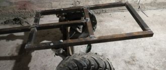
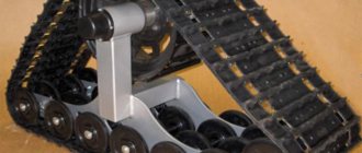
An interesting option is the unusual homemade “assistant” of the FORUMHOUSE user with the nickname Krestik. First, let's show what he took as a basis.
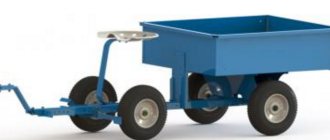
German mini crane with retractable central post
A special feature of the lift is the original folding “arm-boom”, with the help of which the crane, moving on wheels, can reach two opposite walls.
I am building a house myself and, in order to be able to lay aerated concrete blocks, I built a lift according to the above model. The crane was made completely collapsible, except for the base. I didn’t measure the maximum load on the hook, but it easily lifts me (weighing 95 kg).
Technical characteristics of the lift:
- width – 2200 mm;
- height – 4200 mm;
- boom radius – 4200 mm;
- load capacity of electric hoist – up to 800 kg;
- total weight of the crane with ballast is approximately 650 kg;
- lift weight without ballast – about 300 kg;
- The maximum lifting height of the masonry block is 3500 mm.
The working height of lifting blocks is adjustable in two ranges. The first is 1750 mm. The second is 3.5 m, for which the structure is raised, sliding upward along the supporting “legs” using a hydraulic jack lined with spacers made of GB blocks.
To make the lift, the user needed:
- swivel wheels;
- profile pipes for the mast, “legs” and boom with a section of 12x12 cm, 12x6 cm, wall 6 mm;
- pipe-jibs – 63x3 mm;
- powerful gate hinges;
- The boom rotating mechanism is made of ST45 steel and “205” bearings.
During operation, the design was modified. For example, the user laid the cable for the winch in a corrugated pipe and extended the cable for the control panel.
The design has a number of shortcomings that I would like to correct. For example, I’m thinking about making wireless control, replacing the gate hinges with bearings. Increase the number of “joints” in the boom at the same reach. Instead of a temporary counterweight - bags of sand concrete, pour concrete ballast.
Important nuance : in order for the lift to move around a construction site or, for example, on a concrete floor slab on the second floor, you need to keep the workplace clean, because GB fragments and debris interfere with the relocation of the tap.
The design of the unusual lift attracted the interest of portal users.
With such a lift, I think, as they do in Germany, you need to make masonry from blocks larger than standard ones. The length and height are 2-3 times greater than a regular GB. The crane has enough lifting capacity, and the laying speed will increase significantly.
According to Krestik, he heard that someone on the portal had already tried to order blocks of 1x0.4x0.6 m format from a gas silicate manufacturer. But it turned out that this was not profitable for the plant, because it is necessary to reconfigure the line for the production of GB, but for the sake of a small volume (for an ordinary private house) they will not do this.
I'm wondering: is the work on site easier when using a crane? What work can be done with it and what cannot?
There is no need to install scaffolding when laying GB walls. The lift can be assembled and disassembled. I poured the concrete lintels over the windows the old fashioned way, from buckets, because... The volume is small, and it’s easier to do it with one assistant.
The overall result: the mini-crane turned out to be successful, and with some modifications to its design, the lift can be put into small-scale production.
How to make and install it yourself
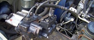
You can install the truck crane yourself. It is installed on the vehicle. To do this, you need to remove the body from the chassis to change the subframe, because The factory design is weak and may crack. The subframe must be made with your own hands because attaching the crane installation directly to the frame is prohibited.
It can be welded from outer (18 mm) and inner channels. The planks are bent so that they follow the shape of the frame. The smaller rail is inserted into the larger channel to form a rectangle. Ready-made channels are attached to the welded frame. A fire hose is placed between them and the base to level the plane of the slats and frame.
The crane is installed on a subframe, which includes:
The installation is secured using special stepladders. It is necessary to insert spacers into the stepladders, which can be made as follows:
To prevent the power plant from moving, it is necessary to weld corners to the base subframe.
After installing the body, you need to leave a gap of 15-20 cm between the body and the truck crane. You also need to connect a hydraulic pump for the operation of the manipulator.
The crane can also be installed on a tractor. For example, you can install INMAN IM-16 on Belarus 80.1.
Source
Programming
The most interesting thing is controlling the manipulator from a computer. uArm has a convenient application for controlling the manipulator and a protocol for working with it. The computer sends 11 bytes to the COM port. The first one is always 0xFF, the second one is 0xAA and some of the remaining ones are signals for servos. Next, these data are normalized and sent to the engines for processing. My servos are connected to digital inputs/outputs 9-12, but this can be easily changed.
uArm's terminal program allows you to change five parameters when controlling the mouse. As the mouse moves across the surface, the position of the manipulator in the XY plane changes. Rotating the wheel changes the height. LMB/RMB—compress/uncompress the claw. RMB + wheel - rotate the grip. It's actually very convenient. If you wish, you can write any terminal software that will communicate with the manipulator using the same protocol.
I will not provide sketches here - you can download them at the end of the article.
How to install a homemade manipulator on a Gazelle
When many options for cranes mounted on the chassis of Gazelle trucks appeared, the owners of these vehicles began to think about how to install this mobile crane on their vehicle. After all, in the end you can get the most popular special equipment. A homemade hydraulic manipulator can have a lifting capacity from 1 to 11 tons. The basis for attaching the CMU to the car frame is the subframe. You will have to do it yourself. It is prohibited to attach the manipulator directly to the frame.
First of all, you will need to move the car body back. This will create free space behind the cabin for installing a truck crane. The best solution is to remove the body from the chassis altogether, because the subframe will need to be replaced. This needs to be done for two reasons:
Servo control shield assembly
The following picture shows the underside of the PCB before it has been drilled and filled with parts:
Since servos can be very noisy when powered, 10uF capacitors are placed on the power rails to help handle peak servo loads during startup. There is also a 100 nF capacitor on the JTAG connector to facilitate power bus disconnection.
Here is an image of the finished unit connected to 7 test servos during program development:
Finally, the mechanics of the robot's arm were tested using a standard RC radio control system to ensure that everything moved correctly and the servos could handle the load on the arm. Tests have shown that the servo control works fully and is sufficient to actually control the hand. The servo drive program works with rotation speed control - increasing and decreasing the servo drive rotation speed, which will be necessary for the operation of the manipulator.
The schematic and PCB design are available for download to all users of the Electrical Schemes website.
GAZ-3309 and GAZ-33098 with a crane-manipulator (KMU)
GAZ-3309 and GAZ-33098 (YAMZ-5344 engine) are reliable vehicles equipped with a crane unit (CMU). The acquisition of this equipment can significantly increase the efficiency of loading, unloading and transportation activities. The main advantage of this vehicle (besides the economic benefits and ease of maintenance and operation) is its versatility. By purchasing one transport unit with an extended on-board platform, you can solve many problems - transporting and unloading cargo of various sizes weighing up to 4 tons. Depending on the needs of the customer, a design with a removable stand and aluminum sides is provided. Technical characteristics: Basic chassis GAZ-3309/33098 Wheelbase, mm 3770 4570 5070 Overall dimensions, mm (max) 6600 x 2350 x 4000 7900 x 2350 x 4000 8950 x 2350 x 4000 Weight of transported cargo, kg 3300 3300 3300 Gearbox 5-speed manual Suspension of front and rear wheels dependent spring Braking system 2-circuit, hydraulically driven, ABS Loading height 1360 1360 1360 Weight of curbed vehicle, kg 3960 — 4160 3750 -3850 4120-4220 Full weight of the vehicle, kg 8180 8180 8180 road clearance, mm 265 265 265 Wheel formula 4x2 4x2 4x2 4x2 are the total number of places 2 2 technical characteristics of the engines: YAMZ-5344 engine diesel mm D-245.7 diesel 4 4 4 4 4 4 4 4 4 4 4 4 4 4 4 4 4 4 4 4 4 4 4 4 4 4 4 4 4 4 4 4 4 4 4 4 4 4 4 4 4 4 4 4 power supply Common Rail Bosch direct fuel injection Ignition system microprocessor microprocessor Displacement, cubic meters. cm 4430 4750 Power kW, (hp) 99 (134.5) 86.2 (117.2) Maximum torque, Nm 417 (42.5) 422 (43.1) Ecology EURO-4 EURO-4 Fuel diesel DT Characteristics of the FERRARI 581 A2 crane: Crane model FERRARI 581 A2 Load moment, tm 7.7 Boom radius, m 7.2 Max. height, m 10.2 Crane weight, kg 990 Load capacity at maximum reach, kg 1030 Main advantages of the 500-series FERRARI CMU: - smooth movement of cargo during the operating cycle - wide model range, with a load moment range from 3.8 to 7.9 tons/ meter - lightweight structure made of high-strength steel - hexagonal boom section - simple and reliable hydraulic safety system - high maintainability and unification of components with cranes of other series Are you interested in our offer? Would you like to receive more detailed information about the terms of cooperation and prices? Contact a sales specialist and you will be provided with complete and comprehensive information support on any questions you may have. 8 8-920 069 3637 8-915 951 4470 by email: product page https://sat-nn.info/kmu3309.htmlTags: gas-3309 with kmu, buy a crane, sale of manipulator cranes, special gas equipment
Results
We are currently working on the electronics and software and will soon tell you about the continuation of the project, so we do not have the opportunity to demonstrate its work yet. In the future, we plan to equip the manipulator with a gripper and add bearings. If you would like to make your own manipulator, you can download the cutting file here. List of fasteners that will be required:
- M4x10 socket head screw, 12 pcs.
- M3x60 screw, 1 piece
- M3x40 hairpin, 1 pc (you may have to shorten it a little with a file)
- M3x16 screw with goal. for H/W, 4pcs
- M3x16 screw with countersunk head, 8 pcs
- M3x12 screw with goal. for H/W, 6 pcs.
- M3x10 screw with goal. for H/W, 22pcs
- M3x10 screw with countersunk head, 8 pcs
- M2x6 screw with goal. for H/W, 12pcs
- M3x40 brass stand female-female, 8 pcs
- M3x27 brass stand female-female, 5 pcs
- M4 nut, 12pcs
- M3 nut, 33pcs
- M3 nut with nylon lock, 11pcs
- M2 nut, 12pcs
- Washers
A lot of time has passed since this article was published. Her first formation was yellow and it was extremely terrible. The red arm was no longer ashamed to show on the site, but without bearings it still did not work well enough, and it was also difficult to assemble. We made a transparent version with bearings, which began to work much better and the assembly process was better thought out. This version of the manipulator even managed to visit several exhibitions:
While making the transparent hand, we understood that this was not the final version. After working with it, we slightly changed the drawings, increased the strength, worked on the assembly and recently assembled the final, white version:
Now we are preparing all the materials for publishing the source code of the project, so add our site to your RSS reader - it will be fun soon!
Hooray! We have finished work on the manipulator! You can meet him here.
Popular models
Loader cranes are produced in:
You can choose a power plant model from the following brands of leading global manufacturers:
Foton units have a load capacity of 6 tons, and their length is more than 6 m. Foton Ollie transports goods and is useful in construction work.
The Isuzu QL 1100 TMA crane installation is one of the new products of the Japanese company. Load capacity - 5.5 tons, length about 6 m.
The Hiab 600EP5HiPro loader crane lifts loads up to 16 tons. It can be used to move large and oversized loads. Equipped with a remote control. This device is capable of lifting loads that are located near its wheels.
The mini crane moves loads weighing up to 3 tons. Popular models:
A suitable crane installation for Gazelle should lift a weight of 800 kg. These are the following models:
Inexpensive mini lift
Practice shows that when building a private house, a real crane is not always needed. Often, a developer can get by with “little expense” and make a small lift based on an electrically driven hoist.
My design is simpler than the authors above, but it suits me quite well. I bought a hoist with a load capacity of 300 kg without a block and 600 kg with a block. Tests have shown that the device can lift a load weighing 250-270 kg, then the engine protection is triggered. During the construction season, I used it to lift about 40 pallets with building blocks, a 6-meter beam for the mauerlat, rafters, mortar for masonry and concrete for the reinforced belt.
The lift, again to save money, is made from used pipes, angles and channels.
All rust was cleaned off with a grinder, and the pipes were sprayed and then painted with paint with a rust reducer.
In order to be able to assemble the lift on the ceiling of the second floor, all components (where welding is not needed) are made dismountable - with bolted connections.
A hoist is installed on the stand using clamps.
In case of rain, a plastic bottle with the bottom cut off is placed on the control panel.
The telpher covers a canopy made of used roofing iron.
When lifting a pallet, two boards are placed under it, and the pallet is lowered onto them.
The entire structure is fixed to the floor with clamps.
Drawing with dimensions of the lift.
These are topics that describe in detail how to make a lift for aerated concrete, and provide dozens of options for mini-cranes, from simple to the most complex designs.
Characteristics
Technical characteristics of the onboard GAZ-53, on which the manipulator is usually installed:
GAZ-53 cars were equipped with 8.25-R20 tires. The gas tank capacity is 90 liters. The rear and front suspensions are dependent leaf springs; the front ones also have telescopic shock absorbers. The GAZ-53 automanipulator is equipped with drum-type brakes on both axles. Due to the lack of power steering, the process of driving this vehicle turns into a physically difficult task.
During the production cycle, various engines were installed on GAZ-53 vehicles, the power of which influenced the vehicle's load-carrying capacity.
Plexiglas cutting
We order plexiglass cutting from a company located near Yekaterinburg. They do it quickly, efficiently and do not refuse small orders. Cutting such parts will cost about 800 rubles. As a result, you will receive cut out parts with plastic film on both sides. This film is needed to protect the material from scale formation.
Plexiglas part with film
This film must be removed from both sides.
Item without film
We also ordered engraving on the surface of some parts. For engraving, simply draw the image on a separate layer and indicate this when ordering. The engraving areas must be cleaned with a toothbrush and wiped with dust. It turned out very well:
Engraving on plexiglass
As a result, after removing the film and grout, we got this:
How to make and install it yourself
You can install the truck crane yourself. It is installed on the vehicle. To do this, you need to remove the body from the chassis to change the subframe, because The factory design is weak and may crack. The subframe must be made with your own hands because attaching the crane installation directly to the frame is prohibited.
It can be welded from outer (18 mm) and inner channels. The planks are bent so that they follow the shape of the frame. The smaller rail is inserted into the larger channel to form a rectangle. Ready-made channels are attached to the welded frame. A fire hose is placed between them and the base to level the plane of the slats and frame.
The crane is installed on a subframe, which includes:
The installation is secured using special stepladders. It is necessary to insert spacers into the stepladders, which can be made as follows:
To prevent the power plant from moving, it is necessary to weld corners to the base subframe.
After installing the body, you need to leave a gap of 15-20 cm between the body and the truck crane. You also need to connect a hydraulic pump for the operation of the manipulator.
The crane can also be installed on a tractor. For example, you can install INMAN IM-16 on Belarus 80.1.
Building a robot arm
Servo bracket assembly
The servo bracket is made of 2mm aluminum sheet. Since you'll need 5 of these staples, it's a good idea to create a template or CNC program to make drilling easier and more consistent.
Now I need to cut a piece of 2mm thick aluminum to size (I used a combination of a miter saw, jigsaw and saw to do this). Place the aluminum in a vise with the template on top and start by dotting the markers and fold lines shown on the template. After this, drill pilot holes for the rest of the bracket.
Remove the aluminum from the vise and drill pilot holes to the correct size as shown in the CAD drawing. To make folding easier, I used a square ruler to mark the fold lines according to the dotted lines: Before bending the aluminum, you will first want to see two lines at the top of the bracket. To bend the bracket, place it in a vise:
Align the fold line and then place the piece of wood over the staple. Fold it back by pressing the wood. This helps maintain pressure even on the bracket and bend it without distorting its shape. You can use the edges of the wood to bend smaller pieces in a similar manner. Once you've finished bending the bracket, use a template and a ruler to mark the cut line on the front of the bracket, and then saw off any unnecessary material: Once the bracket is completely cut and ready, it's a good idea to use a file to smooth out any sharp or jagged edges. The bracket should look something like this:
C-bracket assembly
The C-bracket is designed almost identically to the servo bracket. Here 25mm x 1000mm x 2mm aluminum strips were used for both the template and the brackets themselves. Just like the servo bracket, cut the aluminum to size first and then glue the CAD template on top. The finished template and pattern should look something like this:
Once the bracket is drilled, remove the piece and re-drill the holes to the correct dimensions as shown on the CAD drawings. When bending the bracket, be careful to make sure you bend everything evenly. You will need to make at least three of these braces for the robot arm:
Assembling L-brackets
The robot arm has 3 different L-shaped brackets for the mid-arm, wrist and end mount. Since these brackets are all different sizes, there is no need to create a template. Simply cut the aluminum to size (25mm x 1000mm x 2mm strips) and stick the CAD drawings onto the cut strips. Make a precise strike on the template and then drill the parts.
Assembly of the manipulator
Since the robot arm is relatively heavy, the bottom servo needs sufficient support for smooth rotation. To do this, the arm is mounted on a turntable, which is supported by four rollers that lift the servo off the weight placed laterally across the servo (unsupported, it can easily twist the servo and damage it).
The base of the turntable is made similar to the brackets. The printed CAD template is placed on top of the aluminum sheet and held in place with tape. The cutting and drilling pattern is then point-punched into the material. After removing the paper, use a steel ruler to mark the cut lines:
The resulting shape is then cut out of aluminum and then assembled into the mold. Notice the rectangular pattern in the center of the piece - this is the drilling pattern for cutting out the aluminum so the servo can be installed. This part is drilled and then cut out with a Dremel before being molded so that the servo fits easily into the seat.
To support the top rotating part of the turntable, four small furniture wheels are located around the outside of the piece. These are fairly common items that can be purchased at most furniture stores. The rollers are attached to the base using M4 screws and nuts. After installing the servo and rollers, the lower turntable should look like this:
The turntable base is then attached to four aluminum plates cut from 40mm x 1000mm x 2.5mm rod. Again, the dimensions and drilling pattern are included in the CAD drawings.
To attach the turntable to the robot leg, 4 aluminum tubes (8 mm in diameter and 1 mm thick), cut into 30 mm each, are provided. They are held in place by an M3 threaded rod which is cut to length and then bolted at both ends. Note that the foot is not sufficient to support the robot's arm when it is fully extended to one side (this will cause overbalancing). The plates need to be mounted on a heavier flat surface, but wanted to be able to raise my hand while working on the assembly. The base and leg of the turntable are shown in the following figure:
The upper part of the manipulator is made similar to the base. Before installing the turntable top onto the base, one of the servo brackets is attached to the top. Note that the dual servo arm is slightly raised (on 4 M3 nuts) to provide clearance for the robot arm above the base when rotating the arm's shoulder joint. You will need to drill out the base of the servo mount so that the servo head screw will fit well (to hold the top of the turntable in place). You must ensure that the height of the turntable matches the servo you are using. If necessary, you can raise the rollers by simply placing washers under them.
The following figure shows the design of the dual-servo bracket and mount. The bracket consists of an element with two servos, on which 2 other brackets with servos are in turn attached. Please note that the front bracket has a rear part that allows you to install bracket C on the rear servo before installing the front servo:
How to make a forklift with your own hands using gas 53
Forum exchange of experience on conversion of Gas 66 | Topic author: Francina
Here you can exchange experiences on re-equipment and conversion of Gas 66
Vasya (Chamanit) tell me. The IFA all-wheel drive gearbox with a low-range transfer case is engaged simultaneously with the front axle. If you remove the front driveshaft the car will drive
Homemade (Dierck) In the “Documents” section there are instructions for converting a GAZ-66 car with a D-245.12 S diesel engine
Vyacheslav (Etan) If you take gas 66 and change the engine to D-245, remove the cabin and body.
and weld a new body from ordinary troika metal similar to the GAZ-2975 “Tiger”. The speed of such a car will not be more than 70-80 km/h. Is there any possibility to increase the speed to at least 130? and what problems might arise in general?
Homemade (Dierck) The body must be rigid (frame torsion), attached to the frame through shock-absorbing pads. Diesel D-245 has modifications of 136 HP. and most likely pick up another box for it.
Vyacheslav (Etan) Homemade equipment based on Gas 66 and other loads, leave the frame the same from Gas 66, and weld a body on top of it and screw it to the frame. Which box should I take so that there aren’t too many alterations?
Homemade (Dierck) I posted a post about building a camper, it talks about the types of fastening the body to the frame. Scroll down and look for this topic. It’s better to take the box that comes with the modification of this engine. For a Maz 4770 (notch) it costs 245-136 hp. and zil released a batch with this engine.
Sergey (Saleem) Guys, will you decide whether you need cross-country ability or a speed that is unacceptable for a truck?
Comparison with a universal high-speed car on a platform with independent suspension, a heavy powerful engine, and a huge range in the transmission.
Sergey (Saleem) The same Sadko with his original five-speed gearbox and D-245 gets under a hundred.
Again, you need to understand that the automobile modification has higher speeds than the tractor modification
Sergey (Saleem) If there is a need to heat more than a hundred (and in real life there is no such thing on a truck), then you need to look for a wide-range gearbox (as an option, a Japanese one from a medium-tonnage truck) and then farm there and suffer with the installation, stealing, etc.
Simply installing a high-speed gearbox will mean losing cross-country ability + the risk of tearing it
Vyacheslav (Etan) Sergey, I want to “collective farm” as little as possible, there’s no need to trample 150, about a hundred, but so that the engine doesn’t scream. but my own 66 gas car has enough cross-country ability) I have a Zilov gearbox, but it’s a little lacking in speed (
Sergey (Saleem) Vyacheslav, what is it missing for?
I’m telling you, either you need a particularly high-revving diesel engine, like Nissan’s TD42, or a box with a wide range. but just like this, and not purely high-speed, otherwise you can simply forget about the legendary cross-country ability
Serega (Anice) At a speed of 130 km/h, the gas transfer case 66 will fail
Homemade (Dierck) We install air brakes on Gas 66 Air brakes from Zil on GAZ-66
Homemade (Dierck) See also the album on stripping tires https://vk.com/album-59815220_181882057
Homemade all-terrain vehicle tires. https://strannik-v.ru/topic72.html
Homemade (Dierck) Homemade final drive / gears / https://www.lunohodov.net/forum/viewtopic.php? t=4503..
Homemade (Dierck) Installation of arched tires on Gas 66
Ivan (Jenn) good afternoon. Tell me, does anyone know how to install the gas 66 on the zil. The zil has a D-245 engine... they say that with the gas 66 transfer case the speed will be higher.
Sergey (Saleem) Ivan, it won’t. increased by 66 goes straight, it makes sense to put it only for lower
Oleg (Eliott) good day everyone, I have shishiga dump truck tires worth half a third, the problem is that the front narrow wheels sink in the forest. are there wider analogues?
Tags: How to make a forklift with your own hands using gas 53
Homemade tractor. 4x4 fracture. Engine D-21, clutch and gearbox GAZ-51, transfer case homemade,…
Mechanics
To assemble, you need to cut out parts from 5mm thick plexiglass:
They charged me about $10 to cut all these parts.
The base is mounted on a large bearing:
It was especially difficult to think through the base from the point of view of the assembly process, but I kept an eye on the engineers from uArm. The rockers sit on a pin with a diameter of 6mm. It should be noted that my elbow pull is held on a U-shaped holder, while uFactory’s is held on an L-shaped one. It's hard to explain what the difference is, but I think I did better.
The grip is assembled separately. It can rotate around its axis. The claw itself sits directly on the motor shaft:
At the end of the article I will provide a link to super detailed assembly instructions in photographs. You can confidently twist it all together in a couple of hours if you have everything you need at hand. I also prepared a 3D model in the free SketchUp program. You can download it, play it and see what and how it was assembled.
Advantages and disadvantages
Over the course of many years of operation, the GAZ-53 has managed to establish itself as a simple and reliable truck that is quite easy to repair. This is precisely what can explain the fact that this car, long out of production, is still widely used today. Especially if it has a crane-manipulator installation, which allows you to expand the scope of use of the truck. The car can be repaired in the field; a wide range of spare parts for the GAZ-53 is offered on the market.
If the engine is properly cared for, including timely replacement of oil and oil filters, its service life before major overhaul can be 400 thousand kilometers.
The following can be considered problematic components of GAZ-53 car manipulators:
In addition, the disadvantage of manipulators on the GAZ-53 chassis can be considered high fuel consumption, since the car uses a carburetor engine. This problem can be solved quite simply by installing the MMZ D-245 diesel unit. Reduced operating costs in case of switching to diesel fuel can quickly recoup the cost of replacing the engine. It should also be noted that the GAZ-53 car has a fairly low price on the secondary market, which makes such a manipulator a profitable purchase for limited finances.
Description of design
We took as a basis the manipulator presented on the Kickstarter website, which was called uArm. The authors of this project promised that after completion the company would post all the sources, but this did not happen. Their project is an excellent combination of well-made hardware and software. Inspired by their experience, we decided to make a similar manipulator ourselves. Most existing manipulators involve the placement of motors directly in the joints. This is simpler in design, but it turns out that the engines must lift not only the payload, but also other engines. The Kickstarter project does not have this drawback, since the forces are transmitted through the rods and all the motors are located at the base. The second advantage of the design is that the platform for placing the tool (gripper, suction cup, etc.) is always located parallel to the working surface.
When and to whom it may be useful
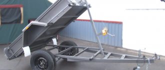
Before we talk about how a homemade crane is made and installed on a passenger car trailer, it is worth touching on the need for such a design. I agree that it may not be useful to everyone and not always.
The presence of a crane on a passenger trailer expands its functionality and increases its performance characteristics. If you regularly transport some heavy objects and do not have a dump mechanism on the trailer, you can use a crane. Possessing certain carrying capacity parameters, it will make it possible to lift various types of cargo on board and lower it from it. Relevant for builders, repairmen, summer residents and just business owners.
In fact, it is an alternative for a manual winch on a trailer. But only the crane has a wider scope of application. This issue is worth considering with specific examples.
The capabilities of a trailer with a crane largely depend on the lifting capacity of the trailer itself and the crane you create yourself. Some models are capable of lifting two tons, but if the trailer platform is not designed for such a load, problems may arise during operation and transportation.
As for the immediate scope of application, several examples can be highlighted.
If you install a crane on your trailer, you can use it:
There are actually a lot of options. They are only limited by the tasks you face and the performance characteristics of the created trailer with a crane.
Electronics
To make the hand work, all you need to do is connect five servos to the Arduino and supply them with power from a good source. uArm uses some kind of feedback motors. I installed three regular MG995 motors and two small metal geared motors to control the gripper.
Here my narrative is closely intertwined with previous projects. Some time ago I started teaching Arduino programming and even prepared my own Arduino-compatible board for these purposes. On the other hand, one day I had the opportunity to make boards cheaply (which I also wrote about). In the end, it all ended with me using my own Arduino-compatible board and a specialized shield to control the manipulator.
This shield is actually very simple. It has four variable resistors, two buttons, five servo connectors and a power connector. This is very convenient from a debugging point of view. You can upload a test sketch and record some macro for control or something like that. I will also give a link to download the board file at the end of the article, but it is prepared for manufacturing with metallized holes, so it is of little use for home production.