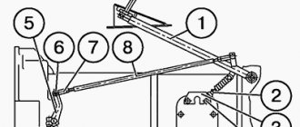
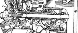
The shafts of first gear and reverse gear belong to the same part. Clutch adjustment and braking of the MTZ tractor: 1 - support bearing; 2 — release lever; 3 — pedal lever; 4, 8 — brackets; 5 — brake rod; 6 - fork; 7 - thrust bolt; 9 - traction; 10 — bracket fastening bolt.
Because of this, slippage occurs. Removing the clutch shaft bearing retaining ring: 1 — retaining ring; 2 — clutch shaft; 3—support cover. Very often, jamming of a broken bearing is accompanied by burning of the ends of the pressure levers. When operating the tractor, it is likely that other breakdowns and failures of the gear shift mechanisms will occur.
If the clutch drive is not adjusted correctly, which is characterized by a lack of clearance between the thrust bearing and the pressure levers, the bearing constantly rotates.
The 3rd, 4th and 5th gear drive gears are mounted on the input shaft splines.
The reverse shaft with the first gear shaft and the intermediate shaft are parallel to the primary one.
If an external inspection of the tractor reveals cracks, kinks, nicks, bends, dents and other defects that are visible without disassembling the mechanism and affecting the performance of the tractor, and when removing the units it is discovered that the technical condition of the adjacent mechanisms requires replacement or repair of a number of parts, then the units are subject to the necessary disassembly , and the parts are defective.
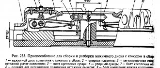
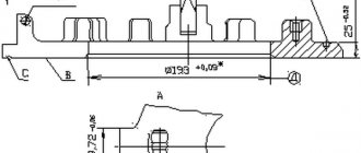
Dismantling the support and pressure disks: 1 - two-jaw puller; 2 — support disk; 3 - technological bolt Acceptable values of controlled diesel clutch data D, mm Thickness of the driven disk 8.0 Warping of the driven disk 0.6 Thickness of the pressure plate 21.0 Thickness of the shaft splines 3.5 Height of the release lever cam 10.9 After replacing the friction linings, the heads sink rivets must be at least 2.0 mm. Rolling out the MTZ 80 tractor
See also: Fuel pump MTZ-50
Adjusting the clutch of the MTZ-82 tractor
Adjusting the free play of the MTZ-82 clutch pedal
When the tractor is operating, due to wear of the friction linings, the free play of the clutch pedal gradually decreases, which should be checked every 125 hours of operation.
The stroke of lever 5 at the radius of pin 6 should be 6.7 mm, which corresponds to a free stroke of 40.50 mm of clutch pedal 1.
Adjust the MTZ-82 Belarus clutch control in the following sequence:
— disconnect rod 8 from lever 5 by removing pin 6;
— by unscrewing adjusting bolt 2, return pedal 1 to its original position until it stops on the floor;
— turn lever 5 counterclockwise until the release bearing stops in the release levers and, rotating the fork 7 of the rod 8, align the holes of the lever and the fork, then shorten the rod 8 by about 5 turns of the fork 7 and connect it to the lever with a finger; check the free play on the clutch pedal pad;
— check the return of the clutch pedal to its original position when retracting it to its full stroke. If the pedal gets stuck, you must loosen the bolts 4 and turn the bracket 3 clockwise or tighten the adjusting bolt 2 to an amount that ensures the pedal returns to its original position.
If the free play of the clutch pedal cannot be adjusted by changing the length of rod 8, and the stroke of lever 5 when measured at the radius of pin 6 is less than 4 mm, adjust the position of the release levers as indicated below.
After adjusting the clutch control mechanism, tighten the locknut and pin.
Adjusting the position of the clutch release levers MTZ-82 Belarus
After installing the clutch on the flywheel and removing the technological bolts, adjust the position of the release levers 3 (Fig. 50) using a special mandrel 4, which is based on the inner diameter of the spline of the hub of the support disk 5 with a stop at the end of the hub.
The mandrel has an end surface for resting the release levers.
The dimensions of the mandrel are shown in Fig. 50. Using adjusting nuts 2, move the release levers all the way to the end of the mandrel and install lock washers 1.
This ensures a distance A=13±0.5 mm from the contact surface of the levers 3 with the release bearing to the end of the hub of the support disk 5.
The difference in this size for the clutch levers should not exceed 0.3 mm.
Clutch malfunctions of the MTZ-82 tractor
Clutch does not transmit full torque
No pedal free play - Adjust pedal free play.
The driven disk linings are worn - Replace the driven disk assembly.
The clutch does not disengage completely
Increased pedal free play - Adjust the pedal free play.
Oil getting into the dry compartment of the clutch housing
Wear of the cuff sealing the crankshaft - Replace the cuff.
The bearing cover of the driven shaft of the PTO drive is pressed out when docking the tractor after repair - Install a new cover or straighten the old one.
Wear of the cuff of the lift bracket - Replace the cuff.
Transmission adjustment parameters MTZ-82 Belarus
The gap between the toes of the release levers and the release bearing of the clutch release, mm - 3
Gap difference for individual clutch levers, no more than, mm - 0.3
Free travel of the clutch pedal, mm - 40-50 along the pedal pad
Distance from the point of contact of the levers with the offset bearing to the end of the support disk hub, mm - 13 ±0.5
Distance from the rear plane of the gearbox housing to the outer end of the main gear drive gear, mm - 58 + 0.15
Permissible increase in the axial clearance in the tapered bearings of the secondary shaft of the gearbox, no more (during control), mm - 0.3
Moment of resistance to rotation of the secondary shaft of the gearbox in tapered bearings without taking into account the gears meshing with it (provided when adjusting the gap), KGSM (Nm) - 0.6 - 0.7 (6 - 7)
Moment of resistance to turning the differential in tapered bearings, applied to the outer end of the teeth of the driven gear of the main gear, KGSM (Nm) - 3 - 5 (30 - 50)
Lateral clearance in the engagement of the rear axle main gear gears, mm - 0.25 - 0.55
Brake pedal travel, mm - 70-90 110 - 120 (for tractors with a unified cabin)
Adjusting and maintaining the cardan drive
If there is wear, be sure to replace parts. The shaft rotates on ball bearings and a bushing connected to the main gear of the second stage of the gearbox. Removing the clutch: 1 - clutch; 2 - technological bolt; 3 — support disk mounting bolt Fig. Share on facebook.
To determine whether a part can be repaired or whether it needs to be replaced, sometimes the interaction of the part with another associated part, for example, a shaft with a gear or a shaft with a housing, is checked.
If the gap is more than 3 mm, the coupling and fork must be replaced. Some boxes are also equipped with gear transmissions. Photo of MTZ tractor
If you do not replace it in a timely manner, get ready for the entire box to jam or, at a minimum, for the bearings to be destroyed. Repair and adjustment of control levers in a reduction gearbox.
Air purifier Air filter. To replace the gear coupling, roll out the core and disconnect the clutch housing from the gearbox.
Minitractor Scout T PTO repair MTZ
Related article: MTZ fuel injection pump regulator
How to adjust the clutch on MTZ 82
When the tractor is operating, due to wear of the friction linings, the free play of the clutch pedal gradually decreases, which should be checked every 125 hours of operation. The stroke of lever 5 at the radius of pin 6 should be 6.7 mm, which corresponds to a free stroke of 40.50 mm of the clutch pedal 1. Adjust the clutch control in the following sequence:
- disconnect rod 8 from lever 5 by removing pin 6;
- unscrewing adjusting bolt 2, return pedal 1 to its original position until it stops against the floor;
- turn lever 5 counterclockwise until the release bearing stops in the release levers and, rotating the fork 7 of the rod 8, align the holes of the lever and the fork, then shorten the rod 8 by about 5 turns of the fork 7 and connect it to the lever with a finger; check the free play on the clutch pedal pad;
- check that the clutch pedal returns to its original position when it is retracted to its full travel. If the pedal gets stuck, you must loosen the bolts 4 and turn the bracket 3 clockwise or tighten the adjusting bolt 2 to an amount that ensures the pedal returns to its original position. If the free play of the clutch pedal cannot be adjusted by changing the length of rod 8, and the stroke of lever 5 when measured at the radius of pin 6 is less than 4 mm, adjust the position of the release levers as indicated below.
Disassembly and repair of the clutch and reduction gearbox of the MTZ-80, MTZ-82 tractor
How to correctly install the clutch and basket on the MTZ Different directions 11 months ago.
In such cases, the repair is carried out by the mechanic himself by replacing it. The following elements are the main elements in the fuel injection pump device:.
Vom MTZ new model. All spare parts are provided with drawing numbers of parts and assemblies.
Contents1 Grain crusher from a washing machine1. Before removing the clutch, it is necessary to tighten the technological bolts into the flywheel, thereby ensuring the initial compression of the pressure springs, see. The principle of operation is that when you press the pedal, the differential lock is activated and the rear wheels begin to work at the same rotation speed, which allows you to overcome difficult terrain. This system is located on a special flywheel, between the gearbox and the engine.
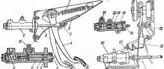
Popular videos. First stage: disconnect rod 5 from bracket 4, turn bracket 4 to the right counterclockwise until it stops; by rotating the fork 6, increase the length of the rod 5 until the fork 6 and bracket 4 are freely connected. Based on the results of the adjustment, the fork is fixed with a lock nut.
Repair of the MTZ 80 tractor gearbox
The reduction gearbox or gap used on the MTZ 80 tractor is used when working with equipment that requires lower operating speeds.
Sunday evening with Vladimir Solovyov from Save now. The pads should fit snugly to the disc; Leaks of up to 0.1 mm are allowed, as well as radial cracks of the linings near the rivets without them extending to the edge or into another hole for the rivet. Pressing out the clutch shaft and removing the drive brake disc of the MTZ tractor: 1 - technological bolt; 2 — clutch shaft. Malfunctions, adjustments. The Council decided in favor of creating a new 1.4 traction class tractor with horsepower.
Before removing the MTZ, MTZ clutch for repair, special technological bolts are screwed into the flywheel, ensuring preliminary compression of the pressure springs Fig. The front axle can be forcibly turned on or off, or activated in automatic mode. In the resulting state, the fork is joined to the bracket. Categories Disassembly into units Repair of units Engine dismantling and repair Major malfunctions Engine repair Cylinder head Cylinder piston group Crankshaft seals Fuel equipment Starting engine Compressor Water pump Engine break-in Dismantling and repair of electrical equipment Generator Starter Locking relay Dismantling and repair Steering Dismantling and repair of the front axle and drive axle Front axle MTZ drive axle Dismantling and repair of clutch and reduction gear Dismantling and repair of gearbox Dismantling and repair of transfer case Dismantling and repair of rear axle and power take-off shaft Rear axle Brakes Axle sleeves Differential locking mechanism PTO power take-off shaft Dismantling and repair of rear linkage hydraulic system Distributor High pressure pump Power cylinder Safety precautions Appendix. If the thickness of the driven disk is not less than the permitted value, and if the rivet heads sag below the plane of the lining by 0.1 mm or even less, then these friction linings are replaced together. Repair of MTZ 82 started from the rear axle, reached the gaps
See also: Repair of MTZ-80
Adjusting the MTZ 82(80) clutch, paw clearance and disc installation
Full adjustment of the clutch is carried out during repair or replacement of the mechanism, as well as during assembly after repair of the engine or mechanisms of the tractor transmission. Correct clutch adjustment ensures the transmission of torque from the engine to the transmission without loss of generated power, and also creates conditions for changing gears of the tractor gearbox and PTO mechanisms. Evidence of the correct operation of the clutch and control drive is the absence of slipping of the disc when the clutch is engaged, and the complete separation of the transmission from the engine when the clutch pedal is depressed.
Adjustment can only be carried out on a working mechanism, taking into account the technical condition of the parts and tolerances in the joints.
Correct adjustment of the clutch of the MTZ 82(80) tractor is done in two stages:
- Installing the release levers relative to the basket hub
- Adjusting the clutch pedal free play
Reinforced clutch housing (not in assembly) for starter 70-1601015-04 MTZ-82P (deck)
Reinforced clutch housing (not in assembly) for starter 70-1601015-04 MTZ-82P , connected to the engine crankcase and gearbox housing, is part of the tractor frame. This cast-iron housing houses the friction clutch of the MTZ-80 and MTZ-82 tractors, a single-disc clutch, permanently closed with a spring pressure mechanism and a torsional vibration damper; there is also a PTO gearbox and a speed reducer.
Main body elements:
Locating pin;
Bolts, gaskets, washers;
Bushings, cover, plug;
Lever, ring and so on.
In addition to the listed spare parts, the clutch housing is equipped with a shift fork shaft. There is also a dust collector body, a special plate, a washer, and a key. In addition, the lower cover, plugs, and clutch cover are built into the clutch housing. This tractor spare part is very strong. High quality metal is used in the manufacture of the part.
Scheme:
The clutch housing can be divided into two parts:
- dry compartment
- gear part.
The dry compartment of the housing houses the Belarus MTZ-82-1, 80-1 clutch, mounted on the engine flywheel. On the release bracket, also located in the dry compartment, a release with a release bearing is installed; the release pins fit into the eye of the clutch release forks.
A grease fitting is screwed into one of the trunnions of the release, designed to lubricate the release bearing. The gear part includes an independent two-speed drive of the rear PTO, a pump drive for the hydraulic attachment system and a reduction gearbox. The independent two-speed PTO drive is designed to obtain two rotation modes on the power take-off shaft shank: 540 min-1 and 1000 min-1.
The drive shaft-gear 30 of the PTO drive, mounted on two bearings, is connected through splines to the floating bushing of the clutch support disk and is in constant engagement with the two driven gears of the PTO drive. The transmission of torque from the driven gears to the driven shaft is carried out through a gear coupling mounted on the splines of the driven shaft. The gear coupling is engaged with one of the gears using a control shaft.
SpetsSnab company has a wide range of spare parts for various types of equipment. We supply only original spare parts or high-quality analogues.
Group of companies SpetsNab
works with individuals and legal entities.
If you have any questions, you can contact our managers.
Delivery of goods is possible throughout
the Russian Federation
.
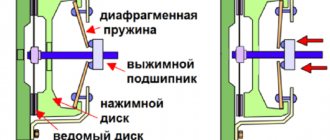
Adjusting the position of the release levers of the MTZ 80(82) clutch
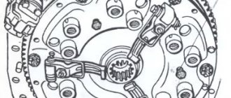
Adjustment is carried out during assembly with the basket installed on the engine and the transmission housing disconnected. Adjusting the position of the release levers of the driven friction disk of the clutch consists of setting the gap between the flange of the splined hub of the clutch basket support disk to the working surface of the lever-claws. The gap is set by tightening the adjusting screws of the feet and should be 12 mm. To ensure uniform squeezing of all paws, the gap difference should not exceed 0.3 mm. This adjustment ensures the position of the working surfaces of the squeezing pads in the same plane, which gives the friction disk uniform contact of its working surface with the engine flywheel, eliminating distortion and uneven wear of the disks when turning on and off.
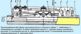
You can check the adjustment using a flat plate or piece of glass. By applying the plane to the paws, check that all points of contact with the paws are in the same plane parallel to the flywheel. To facilitate the installation of the clutch mechanism on the engine flywheel and subsequent adjustment, experienced repairmen use a centering false shaft simulating the diameter of the gearbox shaft splines and the working plane 2 of the release bearing (in the figure). This device ensures the coaxial position of the flywheel and clutch discs during installation, and the simulating plane of the release bearing simplifies the adjustment of the paws. The device can be made from appropriate used ones. shafts of the tractor transmission intermediate box.
Clutch housing - MTZ-80:
1 2 3 4 5 6 7 8 9 10 11 12 13 14 15 16 17 18 19 20 21 22 22 23 24 25 26 27 28 29 30 31 32
List of components from Clutch housing for MTZ-80
Parts diagrams are for reference purposes only! We do not sell all spare parts from the Clutch housing for the MTZ-80 presented in this list. If there is a “Show prices” link in the right column, these spare parts from “Clutch Housing” are on sale. Availability in warehouses for details and prices, see the product card. If there is no “Show cost” link in the right column, we do not sell such parts and do not accept orders for them.
| № | Part code | Name | Part Information | Show all prices |
Adjusting the clutch pedal free play.
The pedal drive is regulated by changing the length of the drive rod 9 (in the figure) for clutch control, due to its threaded ends, providing a gap between the working plane of the release bearing and the claw levers. Correct adjustment gives the clutch pedal a free play of 40-45 mm, while the gap between the paws and the release bearing should be 3 mm. The adjustment is fixed using control nuts on the adjustable drive rod. The gap is measured through the lower hatch of the dry clutch housing with a feeler gauge of the appropriate size.
Current adjustment is carried out when the free play of the pedal decreases, compensating for the natural wear of the linings of the friction driven disk of the mechanism.
Often, machine operators adjust the position of the legs through the lower hatch of the housing, avoiding the time-consuming procedure of disconnecting the transmission from the engine or, popularly, rolling out the tractor. The position of the tabs is adjusted through the lower crankcase hatch when replacing a failed tab or its return spring. Such forced repairs are quite inconvenient due to poor accessibility to the basket mechanism, but are justified by saving time and labor costs. The disadvantage of this adjustment is the difficulty of checking its accuracy. Often adjustment is carried out “by eye”, which leads to misalignment of the planes of the clutch disks, uneven wear, a decrease in the efficiency of power transmission and, as a consequence, a decrease in the working life of the clutch mechanism.
Clutch malfunctions of the MTZ 82 tractor
1 Poor gear shifting with a grinding noise or inability to engage a gear. By squeezing the control pedal, the clutch is not completely disconnected.
Cause : Increased free play of the clutch pedal as a result of incorrect adjustment.
2 When the clutch is smoothly engaged, the tractor begins to move with a jerk.
Cause : Loss of damper springs or rubber bands from the driven friction disk of the mechanism.
3 Clutch slipping when the traction load on the tractor increases or the engine speed increases.
Cause : Incorrect adjustment - lack of pedal free play; wear of the friction linings of the driven disk; oil getting on the clutch discs as a result of a leak in the oil seal of the main bearing of the engine crankshaft, or oil seals in the tractor transmission.
4 Rumble, grinding, slipping, incomplete shutdown when the pedal is fully depressed; the transmitted rotation from the engine is accompanied by jerking and vibration.
Reason ; wear of the release bearing, wear of the working surfaces or breakage of the release levers, breakage of the springs of the release levers, wear of holes for the mounting pin of the levers, breakage or loss of damper springs and friction disk rubbers, wear of the driven disk linings, wear of the surface of the basket pressure disk (thickness less than 21mm), uneven wear of the engine flywheel surface, wear of the splines and play of the hubs of the basket and clutch disc, wear of the axle and drive levers of the release bearing pressure forks.
5 If, after adjustment, the mechanism does not perform its functions, or if it is impossible to adjust it, the unit is dismantled and then completely disassembled with defective parts.
In addition, it should be noted that the service life of the coupling depends on the technical condition of the support bearings of the power shaft. With increased play in the shaft support, the balance during rotation is disturbed, runout occurs in the hubs of the coupling mechanism, and as a result leads to breakdown.
Diagnostics of mechanism parts
To diagnose the condition of the coupling, you need to gain access to the unit. To do this, disconnect the engine from the transmission and roll out the tractor. Then an initial inspection of the unit is performed. Then unscrew the six nuts securing the basket to the flywheel and dismantle the assembly for a full inspection.
Release bearing condition
The bearing is replaced: the contact surface is worn out, it is noisy when rotating and has play in the races, the bearing is jammed.
Practitioners recommend that, in addition to the original bearing of the MTZ 80 tractor, you can install a KamAZ 5320 release bearing, which has proven itself in the operation of the tractor clutch mechanism.
When worn out at the contact areas of the bearing and fork drive, the parts can be restored by welding metal, followed by processing to the appropriate size.
Condition and degree of deterioration of the working surfaces of the feet and their integrity
When the working surfaces of the legs exceed 2.5 mm, they are replaced or welded on with subsequent processing.
When installing new paws, you need to pay attention to the contact plane of the levers with the release bearing. Often, castings of levers have non-identical contours and a contact surface; when applied to a bearing, they protrude beyond the working surface, capturing the part holder. In this case, the protruding part is ground off. When replacing paws, you also need to pay attention to the degree of metal hardness. One of the reasons for the rapid erasure of the feet after repair is the mismatch of the material used or the lack of hardening of the working surfaces of the part.
Condition of the foot springs
If broken springs are identified, all three springs are replaced.
Condition of the basket hub splines
If the splines are sufficiently worn or hub play appears, the basket is replaced.
Friction disc condition
If cracks, uneven wear, lifting of the linings, wear of the hub splines and play, loss of damper springs, as well as sufficient wear of the linings are detected, in all cases the disc is replaced.
Condition of the working plane of the basket pressure plate and the mounting holes for the paws
In case of uneven wear of the pressure plate, leveling by milling and grinding is allowed, taking into account the tolerance of the disk thickness of at least 21 mm. If the mounting holes for the release levers are broken into an ellipse, or if cracks are detected, the disc is replaced with a new one.
Flywheel contact plane condition
If acceptable ellipse of the flywheel surface is determined, alignment is carried out by milling and grinding. If the surface is worn too much, it must be replaced.
After defect detection of parts has been carried out, based on the condition, a decision is made: to carry out routine repairs of the unit with the replacement of worn parts or to replace the assembled unit.
Correct installation of the clutch disc on MTZ 80(82)
- The driven friction disc is installed with the side with the extended part of the hub facing the engine flywheel, otherwise the damper springs will touch the heads of the flywheel mounting bolts.
- The clutch basket assembly is installed on six flywheel mounting studs with bushings.
- Align the clutch mechanism with a prepared false shaft or used one. shaft gaps.
- The six nuts securing the basket to the flywheel are tightened and the positions of the paw levers are adjusted.
- The transmission and engine are connected to the clutch mechanism by placing the shaft splines into the clutch hub splines.
- The connection between the housing and the engine crankcase is tightened.
If you are installing a new clutch mechanism, you must remember to unscrew the three technological mounting bolts from the basket body.
When communicating with professional machine operators, it is often discussed that the success of a repair depends on the quality of the spare parts purchased for replacement. There are a lot of products of dubious quality on the market. When selecting and purchasing, you need to pay attention to the compliance of the linear dimensions of the parts, seats, and the compliance of the material of manufacture, its hardening or carburization, grinding, if necessary, balancing.
The design of the MTZ-82 clutch mechanism
This unit is an integral part of the entire transmission. The need for it is due to the connection and separation of the gearbox and the power plant. In the process of engaging the clutch mechanism, due to the force of friction and sliding, transmission from the engine to the gearbox begins. Thanks to this, you can take off more smoothly from a standstill. If you need to brake, it is possible to smoothly disconnect the crankshaft of the power plant from the transmission.
By its design, a petal clutch consists of friction discs that are pressed very tightly together thanks to springs. Thus, the MTZ-82 clutch basket is made in the form of a dry single-disc clutch, which is of a permanently closed type. As the tractor is used, the friction linings gradually wear out, which reduces the free play of the pedal. For this reason, adjustments are required after every 125 hours worked on such equipment.
Incorrect adjustment or installation of the clutch disc can cause failure not only of the part itself, but also damage and excessively rapid wear of other gearbox elements.
In total, in such a design the main details are:
- Pressure bearing with taps.
- Driven disk.
- Assembled special pressure plate.
For the first time, checking and adjusting the clutch and clutch shaft on such equipment is carried out at the 2nd maintenance. During operation of the MTZ-82, it is necessary to regularly lubricate the bearing, perform tightening and adjustment. Lubrication must be applied every 125 operating hours. The adjustment process is carried out only after the power plant has been completely stopped.
Clutch faults
Even if a new type of clutch basket is used, with frequent incomplete disengagement of the current gears or when the clutch slips over time, early wear is observed, and, accordingly, failure of various parts of the gearbox. In order to determine the cause of the malfunction, you can rely on the main symptoms:
- When there is no free play in the pedal, this indicates that the clutch is not transmitting torque from the engine.
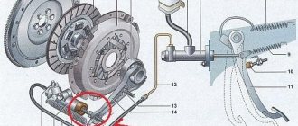
- If oil leaks into the dry compartment, then this situation indicates wear of the cuff, which is responsible for sealing the crankshaft.
- When the pedal stroke is increased, this indicates that the clutch is not completely disengaged.
- The roof of the bearing located in the driven shaft may also be squeezed out. This situation requires the installation of a new cover or adjustment of the old one.
Adjusting the pedal free play
First, you should install the ruler with the emphasis on the ground and press it against the pedal. Then press it all the way, after which the size of the free stroke is set according to the markings of the ruler. So, on a Belarusian tractor this parameter should be at the level of 4-4.5 cm. In this case, the entire pedal stroke should be within 17.5 cm. The pedal adjustment process is carried out by rotating the rod. When fully depressed, the pedal lever must be installed so that it rests on the floor. For this purpose, you should gradually unscrew the special thrust bolt located in the bracket. When it is not possible to achieve the desired result in this way, you need to loosen the bracket bolt and then turn it clockwise. The adjustment is considered complete if the parameters fully comply with the correct specifications specified earlier.
Adjusting clutch foot clearances
In order to begin the adjustment, it is necessary to stop the power plant, as well as put the special equipment itself on the brake. After this, the gaps are checked and, if necessary, adjusted. In this case, the coupling hatch should be removed. Next you need to turn the crankshaft of the power plant so that the release lever is visible. Now you need to use a feeler gauge, whose thickness is about 0.3 cm, to check the gap between the bearing and the lever. If there is a need, they are adjusted. To do this you should:
- Remove the locknuts from the adjusting screw.
- Using a screwdriver, turn the screw enough so that the feeler lever is pressed tightly against the release bearing.
- After this, install the locknut on the tail rotor. It is important that the gap does not change during this process.
A similar procedure must also be carried out with other levers. To do this, the crankshaft is rotated approximately 235 degrees until another release lever appears in the hatch. After all adjustments are completed, the removed coupling hatch should be put back in place.
Clutch replacement procedure
The clutch assembly process is carried out using a special unit. To do this, the disk springs are first compressed, and technological bolts are installed to fix this position. Next, a technological shaft is mounted, allowing the installation of splined hubs.
In general, the process of adjusting the clutch on the MTZ-82 tractor is quite simple. Even a person who is poorly versed in technology can carry it out. To do this, it is important to strictly follow the instructions and not try to make adjustments to the sequence of work yourself.
Dismantling and repair of clutch and reduction gear of Belarus tractor
I came across this myself.
Generator malfunctions.
There is also a creeper that allows you to reduce technological speeds.
Share on telegram. Pressing out the needle bearing of the driven shaft of the PTO drive of the MTZ tractor: 1 - needle bearing; 2 — clutch housing; 3 - inertial puller.
See also: Trailed diskator
PTO MTZ-82 and MTZ-80: repair and diagram.
In addition, the tractor very often did not start from the starter the first time in the winter. The torque is sent directly to the transfer case using the drive shaft. First, you should pay attention to unfamiliar knocks and noises.
When such adjustment is not enough, loosen the bolt 10 securing the bracket and turn the bracket towards the spring clockwise. Adjustment and care of the cardan drive The period preceding the repair of the cardan drive of tractors of the MTZ and MTZ models can be significantly extended, provided that proper care is taken of both the device as a whole and the intermediate support of the cardan shaft, in particular.
When disassembling the clutch, simultaneously with eliminating the identified malfunction, a technical examination of the parts is carried out in order to replace them with new or repaired ones. Next, the torque forces the drive gear, which is part of the main transmission of the front axle, to move. It is imperative to monitor the condition of the crosspiece bearings 7 for the presence of lateral play.
In order to increase it, especially in the last century, machine operators applied the following changes: Removing the MTZ clutch, MTZ for repair 1 - clutch; 2 - technological bolt; 3 - support disk mounting bolt Acceptable values of controlled clutch parameters MTZ, MTZ, mm Driven disk thickness - 8.0 Driven disk warpage - 0.6 Pressure disk thickness - 21.0 Shaft spline thickness - 3.5 Release lever cam height - 10 ,9 After replacing the friction linings, the recession of the rivet heads must be at least 2.0 mm. The model has a semi-frame frame with a front-sprung suspension - on coil springs. It distributes torque over several axes. After adjustment, the fork is secured with a lock nut. PTO drive input shaft. Part 3. Assembly.