Tractor purpose
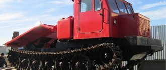
The TDT 55 forest skidder is designed for the removal and collection of cut trees at logging sites; it can also cut branches and drag (skid) processed tree trunks over long distances off-road. Stack logs. It can clear forest areas of cut down stumps with roots and uproot them. With its help you can load logs into wagons. He doesn’t care about taiga wilds, steep slopes, or swampy terrain. It doesn’t get stuck almost anywhere, since the gap between the bottom and the soil is quite large. Performs the most difficult work in logging. Works reliably in 40 degrees of frost and 40 degrees of heat. An unpretentious, reliable, powerful machine.
The tractor has found application in geology. Oil workers and gas industry workers use its power for their needs. In demand in road construction.
Device
Engine
The engine on the tractor is diesel, four-stroke, in-line, with four cylinders, turbocharging and liquid cooling. More modern units used the D-245 diesel engine, and early models were equipped with an SMD-18N-01 or SMD-14BN engine. It is located at the front of the frame.
This model has two fuel systems: main and backup. In normal mode, the main system operates, supplying fuel to the combustion chamber. But if it breaks down or becomes clogged, or if there is a need for additional traction, the backup system immediately turns on. With its help, a broken down tractor will be able to get to the workshop.
Transmission
The clutch (with two discs, dry type) is located in the diesel flywheel housing, to which the gearbox is attached. There is a front brake. When the clutch is engaged, a special locking mechanism is activated, which prevents gear shifting. In total, this model has five forward gears and one rear gear.
Chassis
The tractor's suspension is of a lever-balance type; it is suspended by a spring. It elastically connects the tractor frame and road wheels, as a result of which shocks and shocks are softened. The guide wheel has a crank-type mechanism that allows you to change the tension of the tractor track, as well as a shock absorber that protects the chassis from overloads (if something gets stuck in the track).
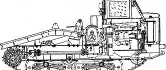
Tractor diagram TDT-55
1 — tractor TDT-55; 2 - frame; 3 - boom; 4 — support rollers; 5 - hydraulic cylinder; 6 - lower rotating jaw; 7 — jaw rotation mechanism; 8 - upper movable jaw; 9 — cabin cover; 10 — protective visor; 11 — boom rotation mechanism; 12 — main hydraulic cylinder; 13 — auxiliary hydraulic cylinder; 14 — transmission casing.
Steering
To disengage the clutch (when you need to stop the car or change gear), a special pedal located on the floor is used. The control drive of this clutch is connected to a hydraulic booster, which facilitates control.
To change gears, a lever is used that can be fixed in six positions. To turn left or right there are two levers, which can also be locked.
To control the winch drive and the power take-off shaft, a separate lever is used, which can turn the drive on, off or in the zero position.
Hydraulics
The hydraulic system is represented by two separate circuits, united by one reservoir. The first circuit controls the movement of the car, making it easier to turn and disengage the clutch. It contains a hydraulic booster containing three sections, as well as an NSh-10 type pump.
The second circuit, consisting of an NSh-50 pump, hydraulic cylinders and a valve-spool hydraulic distributor with two sections, is designed to control working mechanisms. The hydraulic valve spools have four positions. They are controlled remotely, from the cockpit.
Electrics
There is an alternator equipped with a voltage regulator and a 12-volt rectifier and a starter-type battery with a capacity of 75 Ah. Electric fan motors have a power of 15 kW. There are two front and one rear lights, a rear turning light, a lamp in the cockpit, two lamps (one portable, the second mounted above the instrument panel).
Cabin
The cabin cannot boast of a large size; it is single, but it has good visibility and is well insulated. Inside there is a fan and heater, as well as a windshield wiper. The front and right windows open, locking. The seat is height adjustable and secured with a lock nut.
Specifications
Technical characteristics of the skidder TDT 55:
| Characteristics | Indicators | Unit measurements |
| engine's type | SMD-18N-01, SMD-14BN, D-245 | |
| For the SMD-18N-01 engine: | ||
| Power (operational) | 70 | kW |
| Fuel consumption (specific) | 227 | g/kWh |
| For the SMD-14BN engine: | ||
| Power (operational) | 58,8 | kW |
| Fuel consumption (specific) | 218 | g/kWh |
| With SMD-18N-01 or SMD-14BN engine: | ||
| Forward speed | 2,89-12,8 | km/h |
| Reverse speed | 2,69 | km/h |
| Ground pressure (specific) | 44 | kPa |
| Rotation frequency | 1800 | rpm |
| Weight (operational) | 9,6 | T |
| With D-245 engine: | ||
| Forward speed | 3,53-15,65 | km/h |
| Ground pressure (specific) | 40 | kPa |
| Engine power (operating) | 73,6 | kW |
| Rotation frequency | 2200 | rpm |
| Fuel consumption (specific) | 229 | g/kWh |
| Forward speed | 3,53-15,65 | km/h |
| Weight (operational) | 9,3 | T |
| Common parameters: | ||
| Fuel tank volume | 140 | l |
| Winch force (maximum) | 76,5 | kN |
| Track size | 1,69 | m |
| Base | 2,31 | m |
| Track width | 0,44 | m |
| Clearance | 0,555 | m |
| Width | 2,357 | m |
| Cabin height | 2,56 | m |
| Length | 5,85 | m |
The video shows the TDT-55 tractor in action:
Technical characteristics of TDT 55
The technical characteristics of the TDT 55 are such that, due to its power and maneuverability, it is used as a tractor in many types of industrial and construction industries.
There are also disadvantages. If it breaks, repairs are cumbersome. To replace any important part, you sometimes have to disassemble almost half the tractor. The gearbox is difficult to disassemble and remove. Chassis parts are expensive. There are problems with the engine. Sometimes the clutch doesn't work. All these disadvantages are more than offset by its performance, endurance, and maneuverability.
General technical specifications
The TDT 55 skidding tractor weighs 9.6 tons with accessories and has the following parameters:
- Length (with hinged mechanism) – 5 meters 80 cm;
- from the left edge of the tractor to the right - 2 meters 36 cm;
- from the bottom to the soil - 55 cm;
- tractor caterpillar width – 44 cm;
- force – 3000 kg/s;
- The fuel tank holds 140 liters of diesel fuel;
- maximum movement – 13 km. at one o'clock;
- diesel fuel consumption is 224 g/kWh.
The upgraded versions have slight differences from the base tractor. All changes were adjusted to the capabilities of the power plant.
Diesel characteristics
The base tractor has a diesel engine SMD-18N.01, runs on diesel fuel, and has the following parameters:
- the cylinder has a diameter of 12 cm;
- the power plant consumes 6.3 liters of diesel fuel;
- the propulsion shaft rotates – 1800 rpm;
- force – 100 l/s;
- The propulsion unit weighs 800 kg.
The power plant is four-stroke. It has injection, turbocharging, and water cooling. Modernized versions of the tractor have other brands of engines, which differ from the basic one in power.
Not available:
| № | Part code | Name | Part Information |
| 1-65x90-1 | Cuff | Quantity per TDT-55A 2) LHT-55 3) TDT-55A(T) 1 | Not available |
| 12-16-20 | Bolt | Quantity per TDT-55A 2) LHT-55 3) TDT-55A(T) 3 | Not available |
| 12-16-21 | Washer | Quantity per TDT-55A 2) LHT-55 3) TDT-55A(T) 3 | Not available |
| 12-16-22 | screw | Quantity per TDT-55A 2) LHT-55 3) TDT-55A(T) 3 | Not available |
| 12-65G | Washer | Quantity on TDT-55A 2) LHT-55 3) TDT-55A(T) 26 | Not available |
| 2712KM | Bearing | Quantity per TDT-55A 2) LHT-55 3) TDT-55A(T) 1 | Not available |
| 40M-18-146 | Ring | Quantity per TDT-55A 2) LHT-55 3) TDT-55A(T) 1 | Not available |
| 411 | Bearing | Quantity per TDT-55A 2) LHT-55 3) TDT-55A(T) 1 | Not available |
| 4x32 | Cotter pin | Quantity per TDT-55A 2) LHT-55 3) TDT-55A(T) 3 | Not available |
| 4x40 | Cotter pin | Quantity per TDT-55A 2) LHT-55 3) TDT-55A(T) 1 | Not available |
| 55-12-21-1 | Fork | Quantity per TDT-55A 2) LHT-55 3) TDT-55A(T) 1 | Not available |
| 55-18-sb-5 | screw | Quantity per TDT-55A 2) LHT-55 3) TDT-55A(T) 1 | Not available |
| 55M-18-10 | Clip | Quantity per TDT-55A 2) LHT-55 3) TDT-55A(T) 1 | Not available |
| 55M-18-167 | Ring | Quantity per TDT-55A 2) LHT-55 3) TDT-55A(T) 3 | Not available |
| 55M-18-17 | Pad | Quantity per TDT-55A 2) LHT-55 3) TDT-55A(T) 3 | Not available |
| 55M-18-170 | Sleeve | Quantity per TDT-55A 2) LHT-55 3) TDT-55A(T) 1 | Not available |
| 55M-18-18 | Pad | Quantity per TDT-55A 2) LHT-55 3) TDT-55A(T) 2 | Not available |
| 55M-18-2 | Gear | Quantity per TDT-55A 2) LHT-55 3) TDT-55A(T) 1 | Not available |
| 55M-18-20 | Pad | Quantity per TDT-55A 2) LHT-55 3) TDT-55A(T) 1 | Not available |
| 55M-18-21 | Pad | Quantity per TDT-55A 2) LHT-55 3) TDT-55A(T) 4 | Not available |
| 55M-18-33 | Ring | Quantity per TDT-55A 2) LHT-55 3) TDT-55A(T) 1 | Not available |
| 55M-18-41 | Carter | Quantity per TDT-55A 2) LHT-55 3) TDT-55A(T) 1 | Not available |
| 55M-18-6 | Lid | Quantity per TDT-55A 2) LHT-55 3) TDT-55A(T) 1 | Not available |
| 55M-18-sb-108 | Installation | Quantity per TDT-55A 2) LHT-55 3) TDT-55A(T) 1 | Not available |
| 55ML-18-41 | Carter | Quantity per TDT-55A 2) LHT-55 3) TDT-55A(T) 1 | Not available |
| D01-093 | Rym | Quantity per TDT-55A 2) LHT-55 3) TDT-55A(T) 1 | Not available |
| KN-38x50 | Ring | Quantity per TDT-55A 2) LHT-55 3) TDT-55A(T) 1 | Not available |
| М12-6gх30 | Bolt | Quantity on TDT-55A 2) LHT-55 3) TDT-55A(T) 18 | Not available |
| М12-6gх75 | Bolt | Quantity per TDT-55A 2) LHT-55 3) TDT-55A(T) 8 | Not available |
| U-160x0-2 | Ring | Quantity per TDT-55A 2) LHT-55 3) TDT-55A(T) 1 | Not available |
Tractor device
A high-quality welded, rigid box frame is the basis of the machine. The transmission and engine are protected by steel sheets, especially at the bottom of the tractor - where there may be wood chips, twigs, forest and swamp debris. These protective sheets are folding. From time to time, the tractor driver cleans them of debris and dirt. The fact that they are folding allows you to get to mechanisms and parts that require repair.
Fuel is supplied and the clutch is engaged using the pedals. The diesel engine is closed by the hood. The mechanisms are driven by a dry clutch with discs, of which there are two. They have their own brakes and oil boosters. The winch is driven by the power take-off shaft. The tractor has band brakes. There is a rear axle and cardan mechanisms.
The hydraulics are two-chamber, each circuit has its own pump. One circuit is responsible for the movement of the tractor, the other for working parts and attachments. A lever-balance suspension with spring suspension guides the wheels. They have shock-absorbing devices for wheels and tracks. The TDT-55 gearbox is five-speed, has a lock that fixes the position until the tractor driver presses the clutch pedal. This functionally improves the quality and reliability of the mechanisms. The rear axle is driving. A central gearbox, two wheel drives, rotary couplings, gear and clutch control provide movement.
Before starting work, at low ambient temperatures, check the condition of the surfaces of the extended hydraulic cylinder rods. If you find an ice crust on them, carefully remove it with a damp cloth.
Warm up the hydraulic system by performing idle movements of the hydraulic drives, without allowing the full use of the power stroke of the hydraulic cylinder pistons.
Features of hydraulic valve operation
The hydraulic distributor is controlled remotely from the tractor cabin. The hydraulic valve spools can be set to one of four positions: “lift”, “neutral”, “lower” and “float”. The last position ensures free movement of the pistons in the hydraulic cylinders.
The spools in the “raise”, “lower” and “floating” positions are held by clamps. Each hydraulic valve spool has an automatic device set to a certain pressure at which the spool returns to the “neutral” position from the “raise” and “lower” positions.
The automatic return of the spool from the “lift” position occurs at the response pressure of the hydraulic distributor safety valve. From the “lowering” position, the automatic return of the spool occurs at a pressure from 1(10) to 4(40) MPa (kgf/cm2). In this case, the return of the hydraulic distributor handle from the “lowering” position to the “neutral” position can occur during the process of lowering the mechanism. In this case, it is recommended to hold the control handle slightly in the on position.
If the automatic return device fails, manually move the hydraulic valve spools to the “neutral” position.
Return the spool valves from the “floating” position to the “neutral” position manually - with a sharp push.
While the tractor is operating, monitor the position of the hydraulic distributor control levers.
Do not allow the control levers to return incompletely to the “neutral” position to avoid overheating of the hydraulic system fluid.
If the hydraulic distributor control levers do not lock in the working positions, then until the malfunction is eliminated, hold them manually until the end of the working stroke.
Adjusting hydraulic system valve devices
The tractors are equipped with hydraulic units tuned to certain pressures, the valves of which are sealed. Therefore, without
If absolutely necessary, do not proceed to disassemble them. All operations on measuring parameters and adjusting hydraulic units, assessing the technical condition and routine repairs, if such a need arises during operation, must be carried out by a trained specialist using special tools, devices and devices.
Remember that excessively low pressure in the hydraulic system leads to deterioration in the movement (lifting, lowering, etc.) of working parts, and excessively high pressure can lead to rapid wear and breakdown of hydraulic units, damage or rupture of rubber hoses and metal pipelines.
Assess the technical condition of hydraulic units, their performance, and the pressures created using a special device, for example, a throttle-flow meter, consisting of a throttle with a dial and a flow scale, a damping device and a pressure gauge. It is permissible to evaluate the pressure created in the system using a pressure gauge.
Measure parameters and make adjustments on a heated hydraulic system at a working fluid temperature of 50±5° C and rated diesel speed.
Power steering safety valve
To check the operation of the power steering safety valve (diesel does not work), unscrew the threaded plug on the pressure pipe to the power steering and install a tested pressure gauge in its place through the adapter (Fig. 52). Start the engine and warm up the hydraulic system.
Use a pressure gauge to estimate the valve response pressure when the clutch pedal is fully depressed or the steering control levers are pulled back. If necessary, adjust the valve to a pressure of 7.5-8 MPa (75-80 kgf/cm2). Adjust the valve using the adjusting screw. After adjustment, seal the valve. Reinstall the screw plug by unscrewing the pressure gauge.
Hydraulic distributor valve device
Install the pressure gauge through the adapter into the duplicate supply hole with M24X1.5 thread, closed with a screw plug (Fig. 53), and start the diesel engine.
If there is a short-term delay of any of the distributor spools, the pressure gauge should show the safety valve response pressure of 13-14.5 MPa (130-145 kgf/cm2). Adjust valve 1 using the adjusting screw. After completing the adjustment, seal the valve.
