Every motorist who has ever encountered driving a ZIL 130 or 131 car will say with confidence that there are practically no obstacles for this “iron horse”. However, if this is your first time driving such a unit, then you will probably be interested in the ZIL 130 gear shift scheme. Moreover, it is quite original and unusual for the average motorist.
How does the gearbox of the ZIL 130 car work?
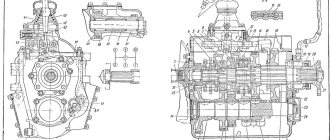
ZIL 130 and 131 cars are equipped with a three-way five-speed manual gearbox. The gearbox of this vehicle allows the driver to move forward at five speeds and backward at one. You can find a drawing of the device below. As can be seen in the diagram, the ZIL 130 and 131 gearbox is equipped with two inertial synchronizers, which include the second and third, as well as the fourth and fifth.
The drive shaft, together with the gear and ring gear to activate the fifth (direct) speed, is installed in the crankcase on bearings. In addition, a cylindrical roller bearing is mounted in the bore of the pulley itself, and the secondary pulley, in turn, rests on it. The intermediate shaft in the ZIL 130 and 131 box is mounted in the lower compartment of the crankcase. There is another gear installed on this shaft, which is in regular mesh with the input shaft (ID) disk. Here, the developers of models 130 and 131 decided to install wheels of second, third and fourth speeds.
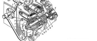
Sectional diagram of the unit with all symbols
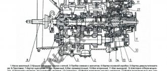
Identification of all transmission components
In addition, spur gears are mounted on the cardan, designed to activate reverse (reverse) gear and first gear. Also, activation of these modes is provided by a spur gear and synchronizer components mounted on the splines of the secondary pulley.
In addition, additional gears are mounted on the secondary shaft:
- to engage second gear;
- to activate the third mode;
- to turn on the fourth.
And these gear rings, when operating, are in constant engagement with the wheels mounted on the intermediate disk. The reverse movement unit is mounted on special roller bearings, which are located on an axis in the crankcase. Here they are installed quite securely. The reverse drive cardan also works in conjunction with the idler pulley through additional wheels.
As for the inside of the crankcase, the working fluid is poured here, so this part is always closed from debris and dust. The switching mechanism itself is installed here. It should be noted that the gearbox switching mechanism on ZIL 130 and 131 is designed in the same way as on GAZ 53.
Switching circuit
The switching diagram for the ZIL 130 and 131 gearboxes is presented below. In general, the scheme is original, but if you believe the words of ZILovodov, then you can get used to it very quickly.
How the transmission lever shifts
Features of correct check of the functioning of the gearbox
To prevent serious damage, after disassembly it is necessary to check the functioning of the ZIL gearbox. During the repair process, it is necessary to purchase original spare parts and components that have similar characteristics and sizes. Be sure to follow the gear diagram.
To check the performance of the gearbox, a special stand is used, which is available at professional service stations. It has a special hole with a drive. The device provides a similar load to check the performance of internal parts and analyze the condition of the transmission fluid container.
A hydraulic regulator is installed on the cover. It allows you to accurately measure the parameters of the current load level. Using 5 brackets, the box is installed to the bracket. Using a coupling, the drive shaft is connected to the electric motor. A control device is connected to the discharge pipeline. As a result, characteristics and parameters are displayed on a special device. They allow you to control the level of load that occurs as a result of the operation of the hydraulic motor.
The functionality of the box can only be checked at a special stand. Before performing the procedure, it is necessary to change the working oil in the power unit in order to obtain accurate results. The stand will allow you to identify components and parts that have failed or need urgent replacement. All assembly and repair work must be carried out in clean conditions. Dirt, dust, and small particles that can cause the gears to jam should not get inside.
How does the gearbox of a car of this brand work?
When the first speed is activated on the gearbox of a car model 130 and 131, the gear wheel begins to move along the grooves and engages with the cardan of the first gearbox mode on the intermediate shaft. In this case, the torque begins to transfer from the primary pulley through gears and other auxiliary elements to the secondary disk. The gear ratio is 7.44.
When the driver engages second speed, the clutch mounted on the synchronizer begins to act on the gear teeth of this transmission. As a result of the fact that this component is already functioning from the components of the intermediate gear, the torque begins to transfer from the primary element to the secondary element. In this case, the moment passes through all the wheels with teeth, as well as the synchronizer cardan. In this case, the gear ratio will be 4.1.
When the driver activates third speed, the synchronizer disc stops affecting the parts and elements of the second gear. The clutch will move along the splines and engage with the third-mode component of the gearbox of models 130 or 131. And this element, in turn, is already engaged with the third-speed wheel of the intermediate cardan. Thus, the torque begins to transfer from the primary pulley through auxiliary elements and the clutch to the secondary pulley. The gear ratio is 2.29.
When the fourth mode is activated, the corresponding synchronizer begins to function. The clutch of this component will move and engage with the gears of the corresponding gearbox mode, which, in turn, is already engaged with the PV wheel. In principle, the process of moving torque is identical to that described above - the torque is supplied to the secondary pulley. Here the gear ratio will be 1.47.
Then, when the driver decides to engage the fifth mode, the synchronizer clutch will engage with the corresponding fourth-speed disc. Further, moving through the movement of the teeth on the PV, the coupling connects both disks into one and it begins to move. In this case, it is carried out on the cardan of model 130 or 131. The gear ratio will be equal to 1.
In general, the process of activating reverse gear is identical to those described above. Only in this case will torque be transmitted from the primary to the secondary through all six gears, and the gear ratio will be 7.09. As you can see, the operating principle of the unit as a whole is not particularly complicated and is quite similar to a traditional mechanical transmission, the difference lies only in certain points.
INTRODUCTION
Road transport is of great importance in the overall transport system of the Russian Federation; its share accounts for more than 2/3 of all freight traffic in the national economy.
The main directions of economic and social development of the country include the development and expansion of the production of trucks and specialized vehicles and buses, primarily diesel ones, an increase in the production of light-duty trucks and electric vehicles for intracity transportation, a significant increase in the production of trailers and semi-trailers to ensure transportation by road trains. Recently, it has been planned to increase the freight turnover of public road transport by 1.3...1.4 times, and the passenger turnover of buses - by 16...18%
Transport is the most important element of infrastructure, which refers to the sectors of the national economy that create its overall functioning. Transport has an active influence on the process of expanded reproduction, the amount of reserves, raw materials, fuel and industrial products, the production capacity of warehouses, i.e. on the efficiency of functioning of various sectors of the national economy.
In this regard, engineers and mechanics of the motor transport specialty are becoming more in demand, who, in accordance with their qualification characteristics, must know the structure of motor vehicles and trends in the development of the design of the car as a whole and the main components and assemblies.
The purpose of this work is to consolidate the knowledge and skills acquired during lectures, laboratory classes and independent work; knowledge of the car as a complex technical system.
Box ZIL-130 diagram
Moving the driven shaft gear forward engages first gear. 2nd gear is engaged by moving the synchronizer clutch back. If you move the synchronizer clutch forward, 3rd gear will engage. By moving synchronizer clutch 2 back, 4th gear is engaged. If you move the same synchronous clutch forward, 5th gear will engage. The intermediate shaft does not participate in the transmission of torque. Reverse gear is engaged by moving the 1st gear gear until it engages with the reverse gear unit.
A gearbox in which a change in torque is produced by changing the gear ratio. The most widespread are the stepped ones:
Gear shift diagram
gearboxes, where the gear ratio is changed by increasing or decreasing the gear ratio. Mechanisms that change the gear ratio continuously within certain limits are called continuously variable transmissions.
» The following types of continuously variable transmissions are used in cars: hydraulic (hydrodynamic and hydrostatic, otherwise called hydrostatic), mechanical (friction and pulse) and electric.
The most widely used continuously variable transmissions are hydrodynamic torque converters, which are usually installed in combination with stepped or planetary gearboxes. Such transmissions are called hydromechanical.
Step boxes are relatively simple in design and cheaper than continuously variable transmissions, but they have a limited number of gear ratios from three to five.
On off-road and heavy-duty vehicles, the number of gears increases due to the use of an additional gearbox. The higher the gear ratio of the gears in mesh, the greater the torque.
ZIL-130 gearbox diagram
Step-by-step transmissions have forced manual control, while planetary and continuously variable transmissions are mostly semi-automatic and automatic. The five-speed gearbox is shown in Fig. 131. Primary (drive) shaft 1 is connected to the engine crankshaft through the clutch. The secondary (driven) shaft is, as it were, a continuation of the primary shaft and is located on the same axis with it.
One end of the secondary shaft is mounted on a roller bearing 10 mounted at the end of the primary shaft, so the secondary shaft can rotate independently of the primary; the second end of the shaft is installed in a ball bearing 8.
Gears are mounted on the intermediate shaft 9. All of them, except for the first gear gear, are made separately and secured to it with keys. To reduce noise during operation and increase durability, the gears that are in constant mesh are helical.
A design feature of the ZIL-130 car gearbox is the presence of constant mesh gears on the secondary shaft. These gears, thanks to special treatment (phosphating) of the mating surfaces of the shaft and the gears of their lubrication grooves, are installed on the shaft without special bushings and bearings.
Checkpoint diagram
In a MAZ-500 type gearbox, the needle bearings of the secondary shaft gears, which are in constant mesh, are lubricated with oil ... under pressure. To do this, a gear oil pump is installed against the front end of the intermediate shaft on the outside of the gearbox housing, driven into rotation from the front end of the intermediate shaft.
shaft The gears are engaged by moving the gear along the splines of the shaft. But in this case, the impact of the teeth is inevitable, since the peripheral speeds of the gears are different. For easy and shock-free gear shifting, it is necessary that the peripheral speeds of the gears being engaged are the same.
The peripheral speed of a gear depends on the number of revolutions of the shaft on which it is mounted and on its diameter: the larger the diameter of the gear and the number of revolutions of the shaft, the greater its peripheral speed. To equalize the peripheral speeds of the gears before engaging them, a special synchronizer mechanism is used, which ensures their silent and shock-free engagement.
PTO power take-off.
Its name hints at the fact that it takes part of the engine torque and transfers it to special mechanisms. This could be a hydraulic pump or a utility equipment attachment. The PTO works in close conjunction with the gearbox, and is activated from the vehicle cabin. A huge amount of load and work falls on this small device.
Therefore, they always strive to make it strong and durable. There are 2 types of PTO, clutch dependent and clutch independent. The first one works when the engine is idling. Dependent PTO is lightweight, easy to install and requires almost no maintenance. They are mounted on a manual transmission and activated by the driver from the cab. An independent PTO can work with both manual and automatic transmissions.
It is installed on concrete mixers, road cleaning equipment, and agricultural machines. The place where the PTO is registered can be a gearbox, transfer case, engine, or the space between the engine and gearbox. KOM is a highly durable unit, but even it can break.
Often, breakdowns are immediately visible; the PTO either stops turning on normally or begins to make loud noise. Problems are solved in different ways, starting with simply tightening the nuts and ending with complete disassembly of the PTO. In any case, without the appropriate knowledge and skills, independent repair of the PTO is not recommended by the manufacturer.
WATCH THE VIDEO
Gear diagram
Primary shaft
The input shaft is made of steel 25 KhGM, the depth of the nitrocarburized layer is 0.6...0.8 mm, the hardness of the surface layer is HRCe 61...66, the hardness of the core is HRCe 37...46.
Basic data on shaft seats, permissible wear of splines, journals and shaft seats for bearings, as well as data on gears.
Thickness of straight spline teeth - 5, 805…5, 855
The diameter of the roller bearing seat is 43.980…44.007
The diameter of the shaft journal for the ball bearing is 60.003…60.023
Shaft end journal diameter - 24.975...24.995
Secondary shaft
The secondary shaft is made of steel 25 KhGM, nitrocarburization depth 0.8...1.1 mm, surface layer hardness HRCe 61...66, core hardness HRCe 37...46.
The runout of the secondary shaft journals relative to the axis is allowed no more than 0.05 mm. The use of necks on crumbled cemented layers of a fatigue nature is not permitted.
Parameters of the secondary shaft journal splines
The diameter of the journal of the front end of the shaft for the roller bearing is 29.939..29.960
The diameter of the journal for the ball bearing is 50.003…50.020
The diameter of the journal for the bushing of the constant mesh gear of the fourth gear is 47.003...47.020
The diameter of the journal for the second gear constant mesh helical gear is 60.920…60.940
Thickness of the tooth of the splined part of the shaft for the synchronizer:
second and third gears - 8.88...8.94
fourth and fifth gears - 10.90...10.95
The tooth thickness of the splined part of the shaft for the first gear gear is 10.88…10.94
Tooth thickness of the splined part of the shaft for the flange - 5.99...5.94
Intermediate shaft
The intermediate shaft is made of steel 25KhGM, nitrocarburization depth is 0.8...1.1 mm, surface layer hardness HRCe 58...61, core hardness HRCe 35...45.
The runout of the intermediate shaft journals relative to the axis is allowed no more than 0.04 mm. Faulty shaft journals can be repaired by chrome plating and then machined to their nominal dimensions.
SYNCHRONIZER
Synchronizers ensure silent operation when turned on. The difference in the rotation speed of the synchronizer clutch and the engagement of the gear is smoothly equalized due to the friction force that arises between them. The gearbox shift mechanism has a locking device that holds the shift rods in the required position.
Synchronizer ZIL-130
The synchronizer for LAZ-695, LAZ-697 buses and the ZIL-130 car (Fig. 132) works as follows.
When clutch 11 is moved to the left using the shift fork, the conical bronze ring will move with it and press against the conical surface of gear 1. The conical rings 7 and the clutch ]] are not connected rigidly to each other, but through three locking pins 5 with balls and a spring. Gear 1 and rings 7 rotate at different peripheral speeds. Until these speeds become equal due to the friction force, coupling 11 will shift (Fig. 132, b).
Synchronizer ZIL-130
Both bronze rings 7 are rigidly connected to each other using pins 12. The coupling 11 will move until the conical surface 10 of the coupling rests against the conical surface 9 of the pin (Fig. 132, a and d). When the speeds of the synchronizer rings 7 and the gear cone 1 are equalized, the pin 12 will be located in the center of the hole of the coupling 11, the blocking conical surfaces will separate (Fig. 132, c and d), and the coupling will continue its displacement. Its outer teeth 13 will engage with the inner teeth of the gear shaft 1, which will thus be connected via a synchronizer to the driven shaft 14.
SOURCES
- Car: Fundamentals of design/N.N. Vishnyakov et al. - M.: Mashinostroenie, 1986. - 304 p.
- Cars: Design, construction and calculation. Transmission: Textbook. allowance/Under general. ed.A.I. Grishkevich. – Mn.: Higher. school, 1985. – 240 p.
- Brief automobile reference book NIIAT. – M.: Transport, 1984. – 220 p.
- Brief automobile reference book. – M.: JSC “Transconsulting”, NIIAT, 1994. – 779 p.
- Litvinov A.S. etc. Car chassis. Design and calculation elements. – M.: Mashgiz, 1963. – 504 p.
- Nekrasov V.I. Multi-stage transmission. Design, construction and calculation: Textbook. – Kurgan: KSU, 2001. – 155 p.
- Osepchugov V.V., Frumkin A.K. Car: Structural analysis, elements of calculation. – M.: Mechanical Engineering, 1989. – 304 p.
- Design of automobile transmissions: Directory / Ed. ed.A.I. Grishkevich. – M.: Mashinostroenie, 1984. –272 p.
- Three-axle cars "Ural" / Edited by A. A. Romanchenko. – M.: Transport, 1978. – 312 p.
- Tour, etc. Construction of automobiles. – M.: Mashinostroenie, 1990. – 352 p.
DOWNLOAD COURSE WORK: .doc | .pdf
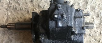
ZIL-130 gearbox design
The car is equipped with a three-way mechanical transmission unit with several operating ranges. Five speeds are for forward movement, one mode is for reverse. The block is equipped with a pair of inertial configuration synchronizers. A primary (drive) shaft is mounted in the box housing, which is aggregated with a helical gear and a ring gear, which is responsible for activating the transmission.
A cylindrical roller bearing mechanism is installed in the boring part of this element. The secondary pulley is placed on it with its front side. In the lower compartment of the housing there is an intermediate shaft with a gear. Three more similar parts are mounted on the secondary pulley.
Gearbox shaft ZIL-130
A spur gear is provided on the splines of the unit in question, which is used to engage first and reverse gears. The block of carriages for the synchronizing mechanism is located in the same area.
The secondary shaft has oblique gears designed to engage the second, third and fourth speeds. They are arranged in such a way as to be in constant engagement with similar elements of the intermediate roller. An axle is rigidly fixed in the lower part of the assembly housing. It is equipped with a reverse speed device with spur gears. They are aggregated with cylindrical roller bearings.
The large gear is in stable mesh with a special part on the intermediate shaft. Inside the crankcase is filled with working fluid (transmission oil). This section is protected by a cover in which the gear shift system is mounted.
Possible gearbox breakdowns
It is possible to determine whether the gearbox is broken or not by the characteristic sounds. Signs of trouble:
- the occurrence of loud noise;
- spontaneous activation of gears;
- oil leak.
If there is strong noise from the transfer case, it is advisable to check the condition of the gears and bearings. These elements must be replaced. When the teeth wear out, the driver may encounter problems such as spontaneous gear shifting.
You need to pay attention to the condition of the sealing elements. With prolonged use of the vehicle, they quickly lose their working properties.
This is the reason why fluid will leak. The membrane in the pneumatic chamber and fastenings must be checked.
Principle of operation
Gear shifting on the ZIL-130 is based on a kinematic scheme with the operation of synchronizers and gears. When squeezing the first speed, the corresponding gear element moves along the splines, interacting with the first gear element on the intermediate roller. From the primary analogue, the torque is transformed to the secondary pulley using constant mesh gears. The gear ratio is 7.44.
When turning on the second speed on the ZIL-130 gearbox, the synchronizer clutch engages with the internal teeth of the working gear. After this, torque is transmitted on the intermediate shaft through a primary analogue and a block of gear mechanisms. The force is applied to the secondary shaft using a synchronizer. Gear ratio – 4.1.
When the third gear is activated, the corresponding clutch loses engagement with the gear, moves along the splines, and begins to aggregate with the working teeth. Moreover, it is already in interaction with the third speed element of the intermediate block. From the primary pulley, the force is transformed using gears and toothed elements, and is then transmitted to the primary shaft through a clutch. The working number is 2.29.
Transfer case repair and maintenance
The transfer case is not so difficult to maintain; there are not many actions required either:
- Seasonal service.
- Regulatory procedures provided by the manufacturer.
- Daily activities.
The latter option involves a pre-trip inspection of the main units that are part of the truck. The ground under such parts is examined for grease stains:
- Engine.
- Gearbox.
- Handout.
- Bridge front, rear.
ZIL 131 coordinates transmissions quickly. Cleaning and checking the reliability of fastening is carried out in a procedure designated as TO-2. It is provided initially by the manufacturer.
There is a special lubrication card, which separately indicates the frequency and order of replacement. TSp-15 is a multi-grade oil that works best on this unit. TSp-10 is a current option for temperatures down to –10 degrees. When draining the liquid, you must unscrew the screw plug. And through a special hole, pour everything inside again.
The transfer case itself is a reliable and stable unit. But you should remove it from the car as soon as the first signs of a malfunction appear:
- The lubricant mixture leaks out.
- "Knocking out speeds."
- Modes switch with a grinding noise.
- Increased noise.
It is more convenient to organize a thorough study of the appearance along with the contents during disassembly, when using a repair area specially equipped for this purpose. Replacement with new analogues is mandatory when faulty parts are identified. Then assembly occurs in the reverse order when performing installation work on the truck. Fill in new fluid and conduct a test drive to test the parts for malfunction.
Separately, if necessary, the switching diagram of the common gearbox on the ZIL 131 is studied.
Activating other speeds
Briefly, the further operation of the ZIL-130 gearbox can be described as follows:
- When the fourth speed is activated, the synchronizer operates, the clutch of which moves, engaging with the corresponding gear teeth. The force of the transmission ratio (1.47) is carried out by means of intermediate gears on the secondary shaft.
- Engaging fifth gear is accompanied by a similar procedure for the action of teeth, synchronizers and their elements of the corresponding part. In this case, both shafts form a single structure, allowing the force to be transferred to the cardan element.
- When the reverse gear of the ZIL-130 gearbox is activated, a special carriage comes into operation. Torque is transmitted through a gear mechanism, and the direction of rotation changes.
Operating principle and design of the transfer case
Torque comes from the gearbox, which is converted and transmitted further by the gearbox. It eventually reaches the wheels and axles located at the rear of trucks. The front-wheel drive is activated automatically or manually. The transfer case supports a low gear, the coefficient of which is 2.08. The relevance of the solution increases in the presence of the following difficult conditions for movement:
- Off-road.
- Soil that has become soggy.
- Loose consistency of snow. In such conditions, any ZIL 131 gearbox often operates, the diagram of which is also described.
All this leads to an increase in torque by at least 2 times. It is transmitted by the transfer case to the wheel drives. Thanks to this approach, the motor does not begin to overheat, which ensures the absence of premature failure of the units.
Transfer cases are characterized by a two-shaft type, helical gears. The basis for the transfer case is a body cast on a cast iron base. The cover at the back and front also complements the overall design.
A PTO is mounted on top of the transfer case plane - a power take-off box. From the car engine, power is transferred to other units with devices in the systems.
The following nuances highlight the appearance of the ZIL 131 transfer case:
- There is a cover on top, with an 8-nut mount on the body. This approach ensures complete tightness of the landing site for the KOM.
- The center is where the drive transfer shaft flange is mounted.
- The front axle drive flange is on the right.
- On the left side, also at the bottom, there is a pneumatic chamber that activates the front-wheel drive.
- At the same level with the drive flange, the rods that control the low gear (rear type) are placed.
The rear appearance also has a number of distinctive features:
- On the left side, rods are mounted on top, which are responsible for the speed of the reduced and direct type.
- On the right side of the same part there are 8 nuts that are responsible for holding the lid. This circuit covers part of the flange so that the box responsible for increasing the power is connected.
- The parking brake drum is mounted at the bottom right. It is combined with a flange that secures the drive shaft for the rear axles.
- The left side is where the oil filler hole is located. Additionally there is a tetrahedral threaded plug. This is the ZIL 131 gearbox, the gear shift pattern is unchanged.
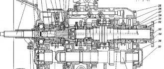
Scheme of work
Below is a schematic representation of the functioning of the node in question with explanations:
- a – transmission device;
- b, c, d, e, f, g – first/second/third/fourth/fifth/reverse speed;
- 1, 4, 6, 7, 8, 10, 11, 14, 15, 16, 18, 19 – helical gears;
- 2 – drive shaft;
- 3 – secondary shaft;
- 5, 9 – synchronizer carriages;
- 12 – block of spur gears;
- 13 – axis;
- 17 – intermediate gear;
- 20 – crankcase.
DIY repair
To repair this unit and adjust the ZIL-130 clutch, you will need a special stand.
The transmission units are assembled in the following order.
- The ball bearing mechanism is installed, for which the retaining ring is placed in the provided groove of the block.
- The bearing is mounted in a special socket on the drive shaft, with the groove of the element facing outward.
- After placing the main shaft on the bench table, the bearing device is pressed in using a special machine. In addition, you will need a mandrel, through which the element is driven into the shaft journal until it stops.
- Using a torque wrench, tighten the nuts with a force of 20 kgm. The bead must fit into the groove of the primary roller.
- The internal parts of the gears are treated with grease or its equivalent, then the roller bearings are installed. The last element should be mounted without interference. After the procedure, diagnostics are performed to ensure that the parts rotate freely without falling out of their sockets.
- The retaining ring is installed.
- Before assembling the second and third speed synchronizers of the ZIL-130 gearbox, three fixing supports are placed in the mechanism, with the milling part facing outward.
- Next, you will need to align the holes of the above parts. Then the rings are pressed in.
- Three fasteners are assembled using springs and balls, which are mounted in the provided slots of the carriage. Similar work is carried out with the second ring installed on the locking pins.
Drive shaft repair
The specified part of the ZIL-130 gearbox is assembled on the table. In this case, the thread should point down. Lubricant is applied to the splines. Next, the first speed gear is installed, the hub groove is directed towards the front part of the input shaft. The correctness of the assembly is determined by checking the presence of its free movement along the splined elements.
Lubricant is also applied to the journal, the second speed gear is mounted, and the ring gear is turned toward the front edge of the secondary pulley. Solid oil is used to treat the thrust washer, which is placed in a seat with a locking ring. The gap between the side of the hub and the specified part should not exceed 0.1 mm. When installed correctly, the gear will rotate freely by hand.
Installation of synchronizing and other parts
Further assembly of the ZIL spare part (drive shaft) continues in the following order.
- The second and third speed synchronizers are placed on the shaft so that the side groove of the carriage faces towards gear No. 2.
- Lubricant is applied to the journal, after which the third speed gear is mounted on the input shaft. In this case, the spline hole is directed to the synchronizer.
- Treat the thrust washer with grease and install it on the shaft. It must be tightly clamped between the bushing and the side of the driven roller (press pressing is used).
- The journal is lubricated, the fourth gear gear is mounted, and the correct position is checked by rotating the part around its own axis.
- The gap between the flange sidewall and the washer is maintained no more than 0.1 mm.
- The installation is completed correctly if the carriage moves freely along the splines.
Gearbox shift mechanism
The characteristics of the ZIL-130 provide for the assembly of the switching unit using a special device that can be found at a service station.
The process flow diagram looks like this.
- The transmission cover is fixed in the device. There is a hole at the end of the tool into which the plug is placed using a mandrel and a hammer, striking the center of the element.
- Assemble the breather, then screw it into the lid.
- Press in a pair of mounting bushings.
- Fixing springs are mounted in special grooves.
- The ball is placed in the left socket using the barb.
- Mount the activation rod for first and reverse gears, having previously applied transmission lubricant to the part.
- Install the rod into the inside of the cover, and the fastening hole should be blocked. Next, install the head and fork of the first and second speeds. The hub is directed towards the holes with plugs.
- Move the rod until the fixation ball and the neutral range socket are aligned. Before this, the blocking elements are installed in pairs.
- Since the dimensions of the ZIL-130, as well as its weight, are quite impressive, the safety heads should be secured securely, additionally securing them with locking bolts. Then cotter pins and plugs are installed.
Transmission lever
This is the last component in the gearbox assembly (its characteristics from the ZIL-130 are discussed above). The procedure is as follows.
- The selector housing is installed on a special machine or in a vice.
- The locking part is placed in the slot on the crankcase of the unit, a cover is put on the selector, and it is placed in its place.
- The ball surface is treated with a layer of lubricant. A spring is inserted behind the crankcase studs, which is installed together with the ball element support.
- Assemble the intermediate lever of the first and second speeds.
- The handle is secured using a nut, and the gasket is secured to the gearbox cover using sealant.
- Finally, the intermediate part is installed in a special slot on the rod head. The second analogue is placed in the groove of the fork. The lever is secured to the body using special clamps with spring-type washers.
How to repair and inspect a synchronizer?
To remove the synchronizer from the gearbox, it is necessary to remove the gearbox from the vehicle. This process requires cost and effort. Dismantling work is carried out according to the following principle:
- first you need to remove the box from the vehicle;
- Next, the bracket that secures the clutch cable is dismantled (to do this, you need to carefully unscrew all the existing bolts and remove the cover);
- the bolt that secures the fork to the structure is also unscrewed without disturbing the thread;
- the synchronizer clutch moves to the lower position;
- the nuts securing and fixing the primary and secondary shafts must be unscrewed;
- the gear located next to the gear needs to be slightly lifted.
After this, you can dismantle the synchronizer, send it for diagnostics, or replace it with a new part. To inspect it, you need to mark the location of the coupling. It is recommended to use a marker or chalk. The location is noted in relation to the hub.
All parts are thoroughly washed with kerosene. After this, you can inspect the hub, coupling, and spline. If the parts are not worn out, there will be no burrs, chips or cracks on their surface. Special attention should be paid to springs and crackers. Parts that have become unusable or are defective must be replaced to restore the functionality of the synchronizer.
Individual components and components are not always on sale; they are produced by manufacturers. You can contact the disassemblers. New parts are thoroughly lubricated with engine oil before installation.
Assembly is carried out according to the marks made. When the position matches, the coupling will fit into the grooves of the hub. To install the crackers, use a screwdriver to make the job easier. After this, you can begin the final installation of the synchronizer and assembly of the gearbox. It is important to carry out inspection, diagnostics and repairs in a timely manner, because malfunctions lead to changes in the gear ratio of the ZIL gearbox.