Uazovskaya checkpoint
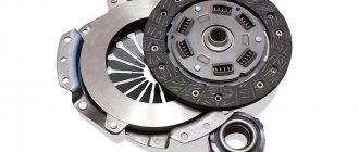
The UAZ gearbox is designed to transfer the force created by the car's engine to the transmission, stepwise changing the speed of rotation and, accordingly, the speed of the vehicle. It provides reverse gear and the ability for the car to stand with the engine running. The gearbox on the UAZ 452 is located under the bottom of the vehicle between the clutch and the transfer case and is attached with studs to the clutch housing. Its weight is about 34 kg.
The operating principle of the UAZ 452 gearbox is based on the mechanical transmission of torque through pairs of toothed gears with different numbers of teeth and different gear ratios. The UAZ loaf gearbox provides 4 forward driving modes with the following gear ratios: 4.12; 2.64; 1.58; 1.00. The reverse gear ratio of the UAZ 452 gear shift mechanism is 5.23.
Device and how it works
The transfer case is a mechanism located in a separate housing made of gray cast iron. The assembly is divided vertically into a crankcase and a cover, which are connected by bolts. Both halves undergo joint processing, so it is impossible to install a part from another gearbox. The crankcase has a separate hatch for installing a power take-off. The oil-filled unit with the parking brake drum installed weighs 37 kg.
The transfer gearbox will only work correctly if it is correctly centered on the gearbox housing. For this, a 2-row angular contact bearing and a steel cylindrical cup are used. The gearbox shafts are mounted on ball and roller bearings, secured with nuts and retaining rings, respectively. The output shafts pass through sealing seals installed in the covers.
The drive shaft of the unit is the driven axis of the gearbox, which is equipped with a splined tip on which the gear is located. This part has 2 positions that allow you to get forward and reduced speeds. The shift drive is equipped with a special fuse that prevents the low range from starting until the front wheel drive is connected.
When the gear is connected to the gear wheel of the rear axle drive shaft, direct transmission is ensured. The gearbox device includes a special lever that allows you to move the gear to the side, engaging it with the gear of the intermediate shaft. In this position, the rotation speed of the driveshafts of the axle drives is reduced.
The design of the transfer gearbox has a movable gear wheel mounted on the middle shaft and controlled by a separate lever. This gear provides connection to the front wheel drive. When the gear is disengaged, the gear continues to rotate as it remains in contact with the rear axle drive gear. This operating principle is necessary to spray the oil in the crankcase.
The plant produced several modifications of the transfer gearbox, which differ in the module of installed gears. Because of this, the gear ratio changed - instead of 1.94 it became 1.47. It is possible to remake the old-style transfer case by replacing gears, since the housing design has remained unchanged.
On some cars there is an imported Hyundai Dymos transfer case (Dymos) with electrical control. The unit weighs 32.4 kg, provides direct and low gears (gear ratio 2.542). The unit is equipped with a controller that diagnoses the box and records error codes. The mechanical part of the imported box is very different from the Russian counterpart - instead of gears, a chain drive is used.
Blog about UAZ
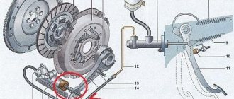
A mechanical four-speed semi-synchronized gearbox was installed on freight-passenger cars of the wagon layout of the UAZ-452 family. The gearbox had four forward and one reverse gears, and was equipped with inertia-type synchronizers to facilitate engagement of third and fourth gear.
Basic technical data of the UAZ-452 four-speed gearbox.
— Center-to-center distance in mm: 80.5 — Maximum torque on the input shaft in kgcm: 17 — Number of pairs of constant-mesh gears: 3 — Helical gear module: 3 — Spur gear module: 3.5 — Gear ratios: first gear — 4 ,12 second gear - 2.64 third gear - 1.58 fourth gear - 1.00 reverse - 5.23 - Splines of the input shaft of the box: number of slots - 10 outer diameter in mm - 35-0.075, 35-0.160 inner diameter in mm - 26.5-0.52 slot width in mm - 5.385-0.05 - Gearbox weight in kg: 34 - Crankcase filling capacity in l: 1.0
Four-speed gearbox UAZ-452, design and operation.
The four-speed gearbox of the UAZ-452 family has three shafts: primary, secondary and intermediate. All mechanisms are mounted in a cast-iron crankcase, which also serves as an oil bath. The front flange attaches the gearbox to the clutch housing. The transfer case is attached to the rear flange of the gearbox housing. The side flange and hatch are used to install the gear shift mechanism.
The gearbox input shaft is mounted on two ball bearings. The rear bearing in the gearbox housing is secured with a thrust ring and a cover, and on the shaft with a nut with a left-hand thread. The front bearing is located at the end of the crankshaft. The front part of the shaft has splines for installing the clutch driven disc.
The rear part of the shaft has a gear ring for driving the intermediate shaft, a ring for engaging fourth gear and a synchronizer cone. There is a cavity inside the shaft where the front support of the secondary shaft is located.
The secondary shaft also has two supports. The front support consists of fourteen rollers located in the input shaft and locked with a wire spring ring. The rear support is a double-row angular contact bearing installed in the rear wall of the crankcase.
The first and second gears are engaged by a gear moving along the splines of the driven shaft, the third and fourth gears by moving the synchronizer clutch, and the reverse gear by a block of reverse gears. The drive gears of the intermediate shaft and the gears of the second and third gears are helical, the rest are straight-toothed.
Synchronizers for the UAZ-452 four-speed gearbox.
The UAZ-452 four-speed gearbox is equipped with synchronizers designed for silent and shock-free engagement of third and fourth gears after equalizing (synchronizing) the rotation speeds of the engaged gear and the driven shaft. The synchronizer works as follows.
When the synchronizer is in the neutral position, there is a gap between the cones of the gears and the locking rings. The synchronizer clutch is in the middle position, and the balls of the crackers are pressed against the middle groove of the clutch. When the gears are engaged, the shift fork, controlled by the driver, begins to move the clutch towards the gear being engaged. Simultaneously with the coupling, the balls move, carrying with them the crackers, which, in turn, rest against the blocking rings.
The cone of the blocking ring slides onto the cone of the gear and, under the influence of friction forces, the blocking ring rotates to the angle determined by the gap between the ring and the cotters. With further movement of the coupling, the balls are recessed into the holes of the crackers, since the force of the springs becomes insufficient. The coupling moves until it stops against the teeth of the blocking ring. When the angular speeds of the clutch and gear are equal and the force applied to the clutch is sufficient to rotate the locking ring, the required gear will engage.
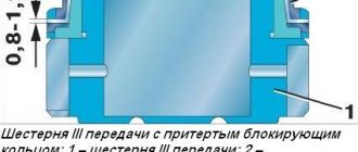
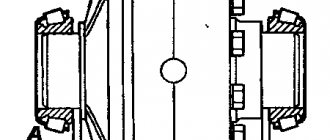
When the parts move mutually by 14 mm, the misalignments in the splines, measured at points T1 and T2, should not exceed 0.35 mm, as shown in the diagram below.
Reverse gear block of a four-speed UAZ-452 gearbox.
Reverse gear in the gearbox is carried out using a block of intermediate gears, which, when the gear is engaged, is connected to the first gear gears of the secondary and intermediate shafts.
The reverse gear block has a bronze bushing, flared to secure it at the ends, and rotates on an axis inserted into the gearbox housing. The axis is protected from displacement by a threaded locking pin.
Maintenance of the UAZ-452 four-speed gearbox.
Caring for the gearbox and drive and gear shift mechanisms involves timely lubrication, checking the connections and condition of the parts.
Transmission oil is poured into the box through the side plug located on the right side. The oil level should be at the bottom edge of the hole. During operation, the oil level in the gearbox may fluctuate, but should not drop more than 10 mm from the edge of the hole.
As necessary, lubricate the gearshift lever shaft in the cab through the connection gaps with a few drops of liquid oil. Particular attention should be paid to fastening the parts of the drive and gear shift mechanisms, since these parts operate under large variable loads and, if poorly secured, can quickly fail.
The most critical points include the nuts securing the levers on the gearbox cover - their tightening should be such that the levers do not swing on the splines, the bolts securing the intermediate lever bracket - loosening these bolts leads to breakage of the bracket, the bolts securing the shift mechanism in the cab - loosening leads to breakage of the bracket, shaft and locknut of the gear shift lever.
How to use
To change speeds, a lever is used that has 3 positions:
- extreme anterior, corresponding to direct transmission;
- average, at which the box is turned off;
- extreme rear to enable the lower row.
Before engaging a downshift, you must activate the front axle drive (using a separate lever). The switching diagram is printed on a special plate, which is attached to the instrument panel. The position of the control levers is slightly different on different UAZ models, but the far handle is always used to control the drive of the front wheels.
Before you start using the transfer case on your UAZ, you should carefully read the instructions. The low range can only be engaged with the clutch open and after the vehicle has come to a complete stop.
When using a Dymos box, switching is performed by a rotary washer having 3 positions:
- rear wheel drive only (2H);
- connection of all-wheel drive and direct transmission (4H);
- lower row and torque transmission to both axles (4L).
The design of the gearbox and its features
The UAZ gearbox includes forks, rods separately for 1, 2, 3 and 4 speed ranges, as well as reverse, clutch, shaft, and cover. Outside there is a drive selection lever, which communicates through a system of rods or corresponding levers with the handle for switching operating modes of the power device in the vehicle cabin.
A mandatory condition for operating the UAZ 452 gearbox, if this condition is met, the gearbox will work properly is to provide lubrication to the gear teeth. The side cover of the UAZ gearbox has a filler hole, and in its very bottom there is a similar drain hole. Both holes are plugged and thereby isolated with conventional screw plugs.
Modernized UAZ gearbox
Having examined the transmission structure of this car model, we can answer the question of how exactly the process of switching gearbox stages is carried out and what happens to the engine running at full speed.
How to disassemble and reassemble
Algorithm for removing the unit from the car:
- Disconnect the propeller shaft flanges from the transfer gearbox.
- Unscrew the attachment points of the transfer case to the gearbox.
- Separate the units by simultaneously removing the locking ring located on the intermediate shaft of the gearbox.
- Remove the gaskets from the mating surfaces.
- Remove the cover of the opening for installing the power take-off gearbox, and then dismantle the gear selection mechanism (together with rods and levers).
- Remove the handbrake drum secured with several screws. After this, you need to remove the rear propeller shaft drive flange.
- Remove the bolts securing the parking brake mechanism to the transfer gear housing. After this, you need to remove the mechanism.
- Remove the flange for installing the front axle drive shaft. Then you need to unscrew the front bearing cap.
- Remove the bolts connecting the crankcase halves. Disconnect the assembly, keeping all internal elements on the cover. It is not recommended to remove the covers and steel bearing cup.
- Disconnect the shift rod stopper and remove the elements using a soft hammer. At the same time, the shift forks are dismantled along with the clamps.
- Unscrew the speedometer drive gear lock.
- Using a screwdriver, remove the bearing retaining rings and then remove the transfer gear shafts.
- Remove the bearings from the shafts using a puller.
- Press out the drive shaft of the rear wheels, remove the oil deflector and the speedometer gear drive. After this, you need to remove the bearing with a puller.
- Disassemble the gear shift mechanism (if necessary).
- Carry out troubleshooting of parts, replace worn elements with new ones. If the housing is damaged, the transfer case must be replaced with a new one.
- Assembly of the unit is carried out in reverse order. It is necessary to install new original gaskets; the use of parts with increased thickness is prohibited.
Read also: The engine icon lit up on the dashboard
It is recommended to disassemble the imported Daimos box in a car service center, since repairs require special equipment. The unit is equipped with electric drives, so it is difficult to adjust the mechanism yourself.
How to fill oil into transfer case
Procedure for changing oil in a Daimos type box:
- Warm up the fluid in the transfer gearbox by driving the car for 15-20 km. Replacement is carried out after 45 thousand km or once every 2 years.
- Wipe the box housing around the filler and drain holes.
- Place a container designed for 2-2.5 liters of liquid.
- Unscrew both plugs and drain the oil from the crankcase.
- Wait 10-15 for complete drainage, replace the plug with a new O-ring.
- Fill the crankcase with 1.8 liters of fresh 75W-85 API GL-4 oil through the filler hole.
- Close the hole with a plug with a new O-ring.
UAZ transmission components
The new UAZ 452 family vehicles have a manual transmission (four-speed). Inertial type synchronizers provide easier gear shifting. The five-speed ADS gearbox is synchronized in all forward gears.
The UAZ can be equipped with a 5-speed manual transmission Daimos (DYMOS). This gearbox is distinguished by its reliability. Its average service life is 300,000 km. The filler plug is located in the middle of the box, the drain is at the bottom. It seems possible to unscrew them using a hex key. When oil is drained, special containers should be prepared. New fluid must be filled to the level of the oil filler hole on the box. The dipstick allows you to accurately determine to what level the liquid is filled. An alternative to the probe can be a long nail. For preventive purposes, the oil level must be measured every 15,000 km.
Replacing the bearing and oil seal
The design of the transfer case allows the replacement of the rear wheel drive shaft seal without dismantling the unit. To do this, you need to disconnect the driveshaft and remove the parking brake mechanism. The old oil seal is removed using a slotted screwdriver.
Replacing bearings without removing the gearbox is not recommended, since the parts are installed with interference. If the bearings are removed from their housings by hand, the gear housing must be replaced with a new one.
The vehicles produced at the plant in Ulyanovsk are classified as off-road vehicles; it is no coincidence that the package includes a UAZ transfer case. The mechanism is designed to distribute the torsional impulse of the motor to the wheels. The design increases the number of transmission gears and torque when moving off-road.
Initially, UAZ vehicles, including the Bukhanka, were developed for the needs of the army. That's why the transmission is simple, unpretentious and requires minimal maintenance. Thanks to these qualities, the car appealed to lovers of hunting, fishing, and tourism. In addition, the transport is suitable for transporting goods in the absence of roads.
Transfer case UAZ-452 “Loaf”:
The device of the UAZ “Bukhanka” transfer case
The UAZ Bukhanka transfer case is a two-stage design without a differential between the axles. The mechanism is also equipped with a neutral message and switchable front wheels. The components are placed in a tray made of cast iron and equipped with a plug. The pallet is attached to the back of the box through the holes of the plates. In addition, the components of the handbrake are also attached here. The main and transition shafts of the box, the drives of the front and rear wheels, are secured by bearings. Between the supports that facilitate the rotation of the shaft, a gear is placed that drives the speed measuring device. The top of the box has an inspection hatch protected by a shutter.
Dymos transfer case for UAZ (finishing):
The control contains two rods with forks attached to a plug. The fork-shaped rods work in tandem with the drive gear and the activation gear for the front pair of wheels. Two control rods are connected to the forks by means of movable pins. There is also a blocking sphere that prevents the activation of low gear when the front wheels are not working.
By activating direct transmission, the UAZ Bukhanka transfer case acts in a similar way so that the main gear moves into the slot of the gear shaft of the rear pair of wheels, transporting the impulse directly. Activating the low gear shifts the main gear so that the impulse is transported to the intermediate shaft and to the gears that drive the axle. Activation of the low stage is only possible after the machine has come to a complete stop.
UAZ Bukhanka transfer case diagram:
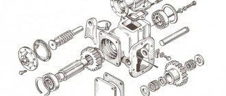
UAZ gearbox design
Gearbox Four-speed gearbox with synchronizers in 3rd and 4th gears
1 — clutch release; 2, 6 - primary and secondary shafts; 3 - retaining ring or nut; 4, 10 — front and rear bearings of the secondary shaft; 5 — synchronizer clutch; 7, 8, 9 — gears of III, II and I gears; 11 — retaining ring; 12 — bolt securing the rear bearing of the intermediate shaft; 13 — bearing of the reverse gear block; 14 — axis of the reverse gear block; 15 — reverse gear block; 16 — spacer sleeve; 17, 18 — gears of the 2nd and 3rd gears of the intermediate shaft; 19 — drain plug; 20 - crankcase; 21 — intermediate shaft drive gear; 22 — intermediate shaft bearing; 23 - nut; 24 — intermediate shaft; 25 - plug; 26 — cover of the front bearing of the input shaft.
Four-speed gearbox with synchromesh in all forward gears
1, 16, 23 - primary, secondary and intermediate shafts; 2 — front bearing cover; 3 - special nut or retaining ring; 5 - gasket; 6 — input shaft bearing; 7 — front bearing of the secondary shaft; 8 — crankcase; 9 — synchronizer clutch for 3rd and 4th gears; 10, 11 — gears of III and II gears; 12 — synchronizer clutch for 1st and 2nd gears; 13 - 1st gear gear; 14 — locking plates; 15 — bearing; 17 — retaining ring; 18 — washer; 19 — spacer ring; 20 — intermediate shaft bearing; 21 - special bolt; 22 — special washer; 24 — reverse gear axis; 25 — reverse intermediate gear; 26 — drain plug; 27 — gear block for driving the intermediate shaft and 3rd gear; 28 — retaining ring; 29 - plug; 30 - roller bearing.
Five-speed gearbox
1 - input shaft; 2 — bearing cover; 3 — cuff of the input shaft; 4 - retaining ring; 5 — ball bearing of the input shaft; 6 — roller bearing of the secondary shaft; 7 — splined crown of the input shaft; 8 — blocking ring; 9 — synchronizer clutch for 3rd-4th gears; 10 — coupling hub; 11 - key; 12 — splined ring of the 3rd gear gear; 13 — third gear gear; 14 — gear bushing; 15 - 2nd gear gear; 16 - crankcase; 17 — 2nd gear bushing; 18 — splined ring gear of the 2nd gear; 19 — synchronizer clutch for 2nd-1st gears; 20 — splined ring of the 1st gear gear; 21 — 1st gear gear; 22 — bushing of the 1st gear gear; 23 — roller bearing of the secondary shaft; 24 — secondary shaft bushing; 25 — fifth gear driven gear; 26 — 5th gear housing; 27 — double-row ball bearing of the secondary shaft; 28 — spline washer; 29 — retaining ring; 30 - secondary shaft; 31 - bolt; 32 — disc spring; 33 - support ring; 34 — drive gear of 5th gear; 35 — splined ring of the 5th gear drive gear; 36 — synchronizer spring; 37 — synchronizer block; 38 — 5th gear synchronizer clutch; 39 — ball bearing of the intermediate shaft; 40 — roller bearing of the reverse gear; 41 — reverse gear; 42 — reverse gear axis; 43 — gear block for driving the intermediate shaft and 3rd gear; 44 — intermediate shaft; 45 — roller bearing of the intermediate shaft; 46 — bearing cover.
UAZ vehicles are equipped with three types of mechanical three-shaft gearboxes:
— four-speed, with synchronizers only in 3rd and 4th gears; — four-speed, with synchronizers in all forward gears; — five-speed, with synchronizers in all forward gears.
Four-speed gearboxes are interchangeable, but may have different sizes of input shaft splines (for different clutch drive discs). Five- and four-speed gearboxes are interchangeable complete with their transfer cases and driveshafts. When installing a five-speed gearbox instead of a four-speed gearbox, it is also necessary to modify the body floor hole for the transfer case levers. The components and parts of different gearboxes are not interchangeable.
The four-speed, partially synchronized gearbox consists of a one-piece cast-iron crankcase in which the primary, secondary and intermediate shafts are mounted on ball bearings. The front end of the secondary shaft rests on a roller full complement bearing in the bore of the rear end of the primary shaft, and the rear end rests on a double-row ball bearing, along which the gearbox and transfer case are centered.
The drive gears of the intermediate shaft, as well as 2nd and 3rd gears, are helical, constant mesh. Splines are installed on the intermediate shaft of the gears of the 2nd and 3rd gears. Bronze bushings with holes and honeycomb knurling are pressed into the holes of the gears of the 2nd and 3rd gears of the secondary shaft to improve lubrication. To supply oil to the bushings, radial holes in the gears and helical grooves on the shaft are used.
III and IV gears are engaged by moving the inertial synchronizer clutches on the secondary shaft. The driven spur gear of the 1st gear moves along the splines of the secondary shaft. 1st gear is engaged by moving the driven gear backward along the splines of the secondary shaft until its teeth engage with the teeth of the drive gear. By moving the 1st gear driven gear forward, 2nd gear is engaged (its splined rim is connected through the 1st gear gear to the secondary shaft). In addition, the driven gear has a middle position. In this case, it is used to engage reverse gear.
Checking the transfer case
The advantage of the unit that distributes the torque impulse is that the device requires minimal intervention and maintenance. Manipulations consist of monitoring the level and changing the lubricant, inspecting connections for damage. Before working with the box, the product is cleaned. This helps detect hidden cracks and leaks. If such symptoms are detected, they find out what the cause of the phenomenon is. Faulty parts are replaced, as a rule, these are sealing elements and oil seals.
Read also: Window whistles, what to do
After cleaning and visually inspecting the surface of the transfer case, check the lubricant level in the product. If there is not enough liquid, the substance is added. At the same time, check the lubricant in the gearbox; the value corresponds to the lower edge of the filling hole. If the fluid level in the transfer case is low, but is high in the gearbox, topping up is not necessary, since the total amount of the substance has not changed.
A detailed inspection of the box involves dismantling the product. After washing and air drying, the unit is inspected. The pallet and plugs are checked for cracks and chips. Oil seals and seals are replaced with new ones.
Changing the oil in the UAZ transfer case:
They check that the condition of the working parts on the shafts and splines corresponds to the standard, so that the gear teeth are not worn or chipped. Even if the damage is small, the product must be replaced. Attention is paid to the bearings; abrasions on the ring tracks are not acceptable. They also check separators, spheres, rollers, etc. Gaps, fragments, knocking, uneven movement are a signal to change the product.
The rods and forks become jammed and deformed, the elasticity of the spring elements is lost, and then the products are replaced. In addition, you should pay close attention to switching when the transfer case levers of the UAZ Bukhanka stick and jam. The coupling teeth are checked for damage. The weak link of the differential is the satellite. Small defects force the product to be polished, or in the worst case, replaced.
Causes of breakdowns
As a rule, the need to replace the main components of a gearbox arises due to their natural wear and tear.
The main reason for oil leakage from the gearbox is the presence of an increased level of fuel in the system. For UAZ gearboxes, you should use high-quality oil. If the liquid is not of the proper quality, this may cause characteristic noises from the box. When the synchronizer or its parts wear out, it is always difficult to change gears. You should also pay attention to the details of the switching mechanism. When gear teeth are deformed, gears often switch off automatically.
Causes and troubleshooting
The design of the UAZ gearbox is reliable, trouble-free and durable. However, problems with equipment occur due to errors in use and violation of established regulations.
| Source and symptoms | What to do |
| Exceeding the permissible hum level of a working device | |
| Erasing the gear teeth of the box. | Replace worn out box items. |
| Weak fastening of the transfer case to the box, or reduced fixation of the bearing caps. | Tighten the fasteners, if the symptom recurs, dismantle the product and eliminate the defect. |
| Bearings are worn out. | Replace erased items. |
| Saturation of the working fluid with wear products from the box. | Remove the pan, wash it, change the oil. |
| Incorrect oil used, low fluid filling level. | Change the working fluid, set the desired level. |
| Carrying out repairs to replace gears, without selecting a product to minimize noise. | Check the gears for noise and replace them with the required ones. |
| Switching steps is difficult | |
| Different wheel wear. | Replace with wheels with the same tread and equalize the internal pressure. |
| The joints of the longitudinal projections of the main and the mediator shaft are jammed. | Sand the areas with burrs; if that doesn’t help, change the elements. |
| The drive gear has damage on the teeth of the small ring. The shift fork rod is bent. | Sand the damaged areas, straighten the rod, if that doesn’t help, change the element. |
| The switch rods are stuck on the axle. | Separate the parts, clean the axles and pipes, coat with lubricant, and connect the product again. |
| Spontaneous speed shutdown | |
| Erasing the teeth of the gears of the box. | Replace worn out box items. |
| The box bearings are worn out. | Replace worn box elements. |
| A large gap in the articulation of the shaft and gear. | Select the gear according to the size of the longitudinal protrusions. |
| The transmission is unable to engage because the mechanism is bent or there is damage to the gears and cylinders. | Correct bends, sand damage, or replace parts. |
| Poor functioning of the locking mechanism, loss of elasticity of the spring mechanism, abrasion. | Replace erased items. |
| Leakage of working fluid | |
| Violation of the integrity of the sealing elements of the pan, bearing caps, and the transfer case’s articulation with the gearbox. | Replace sealing elements. |
| Weak fastening of the cover, bearing, pan, joints. | Tighten connections. |
| Violation of the integrity of the shaft seals. | Replace the damaged element. |
| Violation of the integrity of the tray or lid. | Replace the damaged element. |
| The plugs of the switching rods, switching rods, and the plugs of the front bearing of the middle shaft fall out or are broken. | Change the plugs. |
| Bearings are damaged | |
| No, or a small amount of lubricant. | Change or add fluid. |
| Demolition of cages and bearing rings due to abrasive. | Change the elements, dismantle and wash the pan, change the working fluid. |
| Excessive shaft bearing friction. | Disconnect the element, clean the product, and coat it with lubricant before reassembling. |
The distributor needs careful handling and periodic inspection. Often, the reason for the breakdown is trivial driving on wheels with a violation of the pressure regime. Continuous use of the front pair of wheels is not allowed; the product is used as needed. Operation is affected by the use of spare parts that do not meet the required quality.
Repair of UAZ Bukhanka transfer case
Serious repairs to the UAZ transfer case are rarely performed. As a rule, to restore normal operation, adjusting the product and lubricating problem areas is enough. If repairs cannot be avoided, then the operation to return the box to its former functionality is done in strict order.
- Dismantling the transfer case;
- Disassembling the transfer case;
- Fault detection;
- Troubleshooting (replacement, restoration of parts);
- Transfer case assembly;
- Installing the transfer case in place;
- Functionality check and configuration.
Read also: How to replace a valve cover gasket
Before carrying out work, select the necessary tools; for this, find out the type and type of transfer case. Functionally, repair is the replacement of damaged parts with new ones, for this reason more attention is paid to the rejection stage.
- Oil seals (changed during disassembly, regardless of the degree of wear);
- Gears (parts cannot be repaired due to the loads they experience);
- Forks and splines (elements affect the quality of work and safety);
- Bearings;
- Protective casing (if cracks or chips are detected, the part is replaced).
UAZ transfer case control mechanism:
UAZ Bukhanka transfer case control
The UAZ Bukhanka transfer case is controlled remotely from the driver’s cab. The levers used to manipulate the car are located on the right side of the user. The upper rod activates and deactivates the front pair of wheels of the car, has two positions: top (the bridge is activated), bottom (the bridge is deactivated).
Position of the transfer case levers of the UAZ Bukhanka:
The location of the transfer case levers on the UAZ Bukhanka is possible in three options. First, the main gear is activated, middle (zero), the main shaft does not rotate, second, low gear is activated.
In order to avoid damage to the transfer case if the gear is incorrectly activated, a locking device is provided. The product is fixed in the cover of the gear change rods. Thanks to the fuse, the low gear is activated after the front pair of wheels is activated. Meanwhile, the front pair of wheels is not activated when a downshift is engaged. A solution has been implemented with a ball acting as a lock. The sphere in the cover prevents the rods from moving and deactivates the front pair of wheels until the rods are put into downshift. The lock prevents the driveshaft and rear pair of wheels from being overloaded.
There are single-lever control elements, one rod alternately activates: the front pair of wheels, zero, then low stage.
The UAZ-452 was originally created for the Soviet armed forces as a medical service vehicle, where it was therefore dubbed the “tablet” (the civilian nickname is “loaf”).
Therefore, the design of the mechanisms, including the transfer case, is simplified as much as possible.
During operation, the entire transmission system is unpretentious, which is confirmed by half a century of practice. The only recommendation from the manufacturer is to periodically check the oil level and check the fasteners.
In addition, if necessary, the front linkages should be adjusted and the lever axles should be lubricated on a preventive basis. This mechanical unit, including bearings, does not require any further maintenance or adjustment.
Operating principle
Car checkpoint
In order to understand and imagine how the process of changing the speed modes of the engine and the corresponding indicator of the permissible speed occurs, let us turn to a short explanation. The lower stages, which ensure the vehicle starts, are activated by the most powerful gear, which moves along special skids located on the driven shaft. This action allows you to transfer enough force to a heavy car for the car to start moving.
As soon as the car starts moving, you can switch to second gear, due to which the car does not stop and its movement is not very fast. However, the second speed stage will not be enough if you need to reach a speed of about 40-50 km/h. In this case, higher gears will be required.
As for the 3 and 4 speed modes and the corresponding gears, which provide a high number of revolutions per second, they are controlled by a synchronizer clutch. Some modifications of the gearbox on the UAZ 452 were produced, where the switching of 1st and 2nd speed modes of the transmission was also carried out using an additional synchronizer clutch. However, in this case we are considering a transmission option with one synchronizer clutch.
The UAZ gearbox has a synchronizer, which is designed to smoothly switch on modes by equalizing the rotation speeds between the intermediate and driven shafts. This feature of the device not only provides more comfortable driving, but also protects the leading clutch mechanisms from damage and rapid wear.
Features of the box
The UAZ-452 transfer case is the heart of the car’s transmission. It transmits dynamic force to the front and rear axles and has 2 operating modes: direct and reduction (with a gear ratio of 1.94).
The latter helps create more efficient traction when overcoming off-road conditions and terrain folds.
During assembly, the operating gears of the transfer case are mounted taking into account the noise emitted during rotation. When a worn gear is replaced with a new one during operation, an increased level of noise often occurs in the gearbox, which is not dangerous and usually goes away over time.
Transmission diagram
Let's look at an example of a gearbox design diagram and the features of this unit. The engine gearbox housing contains several types of drives, including:
- transmission drive shaft;
- intermediate shafts;
- driven shaft of the UAZ 452 gear shift device.
Bearings serve as supports for these nodes of the transmission. It is worth paying attention to the picture posted here. The diagram on it explains in sufficient detail the structure of the transmission: the front bearings are roller type, and the rear bearing has a double-row ball modification. The driven shaft has a front bearing mounted into the end of the drive shaft. The driven axle is equipped with gears of 1st, 2nd, 3rd gearbox operating modes, and the intermediate one is equipped with gears of 2nd and 3rd gears of the UAZ 452.
As the diagram of the UAZ 452 gear shift device shows, the 1st stage gear has a larger diameter and is located in the rear part of the driven shaft, while the gear from the third mode is the smallest in size, located in the front part of the driven shaft, next to the synchronizer clutch.
In the lower part of the crankcase, where a separate axle is located, reverse gears are installed. The side cover of the gearbox hides inside the crankcase a control device for switching engine operating stages. A gear mechanism is mounted in its rear part to send readings to the speedometer.
Unit repair and maintenance
Signals for repairs can be:
- Oil leak.
- Increased noise and vibration.
- Difficulty switching from one position to another.
- Spontaneous loss of the switched on operating mode.
Although often, to fix problems, it is enough to just adjust the fasteners or lubricate problem areas and points. If this does not help, the car must be driven into an inspection pit or overpass, after which technological operations must be carried out in strict sequence.
Repair stages:
- dismantling and disassembling the box;
- failure detection;
- elimination of the causes of malfunctions (replacement or restoration of parts);
- assembly, installation in a regular place, adjustment.