Adjusting engine valves on a ZIL 130 car, as on other engines, requires knowledge of four basic rules
- Where is the first cylinder located? Because all visible marks on the pulleys correspond to the position of the piston of the first cylinder at top dead center (TDC).
- In what position of the crankshaft is the piston of the first cylinder at TDC during the compression stroke? In this position, the intake and exhaust valves are closed and the valve clearances are adjusted.
- It is necessary to know the operating order of the cylinders of a particular engine. That is, which next cylinder will start working. To turn the crankshaft and begin adjusting the next cylinder in sequence.
- It is necessary to know at what angle the crankshaft must be turned to bring the piston of the next cylinder to TDC during the compression stroke
These four rules apply to all four-stroke internal combustion engines. Having mastered these points well, you can adjust the valves without the help of specialists.
Setting TDC at the moment of compression
The problem arises when the piston becomes in the correct position to adjust the valves of the first cylinder. The piston must be at TDC during the compression stroke. There is a mark on the crankshaft pulley. It needs to be aligned with the TDC designation on the scale.
Indeed, the piston of the first cylinder will rise to TDC. But it is necessary to make sure that it is in the compression stroke. Because for the full cycle of engine operation from the first to the eighth cylinder. The piston becomes twice at TDC. We are only interested in one of its positions. This position can be determined in several ways.
- If the engine is in working order on the car. You can remove the tip from the spark plug wire going to the first cylinder. And turn the crankshaft with the ignition on. At the moment a spark jumps between the wire and ground. You should place a mark on the pulley with the TDC designation on the scale. The spark will jump before the piston reaches top dead center. And by setting the marks, the piston will move to the desired position.
- You can unscrew the spark plug of the first cylinder and plug the spark plug hole with a paper plug. When cranking the crankshaft, the plug will shoot out. All that remains is to align the mark on the pulley with the TDC mark on the scale. You can simply plug the hole with your finger. When air starts to come out from under it, all you have to do is align the marks. This indicates that compression is forming in the cylinder. Compression begins. Therefore the valves are completely closed.
- Visually, the TDC position is determined by the rocker arms. In the compression position when the piston approaches TDC, the rocker arms are not movable. The valves are closed. In the second position, when the piston approaches TDC, one valve closes. The second one, after passing TDC, begins to open immediately. If the valves are stationary, all that remains is to align the marks.
After the piston of the first cylinder is in the correct position, it is necessary to adjust the valves of the first cylinder.
Ignition coil B114-B
coil
Basic technical specifications are given below.
Rated voltage 12
Low voltage winding: wire diameter, mm 1.25…1.33
number of turns 179…182
resistance at 20 °C, ohm 0.42
High voltage winding: wire diameter, mm 0.06
number of turns 41000…41700
resistance at 20 °C, ohm 223000
Additional resistance: wire diameter, mm 0.7
resistance at a temperature of 20\°C, ohm 1.04
Overall dimensions of the ignition coil, mm:
length 156
width 68.5
height 82
coil
The ignition coil is located on the front panel of the cab. It has two primary circuit winding terminals. When installing the coil, you must ensure that the wires are connected correctly.
To terminal “K” you need to connect wires from the same terminal of the switch; to the unmarked terminal - a wire from the switch.
The ignition coil is designed to work with a transistor switch only. The use of ignition coils of other types is unacceptable. On the B114-B ignition coil there is the inscription “For transistor system only.”
The ignition coil windings are checked for sparking on a bench. The absence of sparking or an unstable spark indicates a malfunction in the coil winding. To determine the state of the windings (turn circuit of the primary winding), their resistance is measured, which must correspond to the technical specifications.
Malfunctions in the windings of ignition coils most often manifest themselves as a result of their overheating, which occurs when the primary circuit is not open and left with the engine not running and the ignition not turned off. In this case, the ignition coil can heat up to 120 °C or higher. The ignition coil cannot be disassembled and is replaced if it fails.
An additional resistor, consisting of two resistors connected in series, is installed next to the coil. When the engine is started by the starter, one of the resistors in the series circuit is automatically short-circuited, thereby increasing the voltage at the moment of starting.
It is necessary to ensure that the wires are connected correctly to the terminals of the additional resistor: a wire from the starter must be connected to terminal VK; - to terminal VK-B from the ignition switch; and to terminal K - from the terminal of the transistor switch. When replacing spirals, the additional resistor is removed from the car.
Distributor
Figure 9-17. Distributor
1- roller; 2- plate; 3- felt; 4— slider; 5- cover; 6-pin angle; 7- contact spring; 8- contact; 9- lid latch; 10—centrifugal regulator; 11 — bolt securing the top plate to the body; 12-plates octane corrector; 13- eccentric; 14- lever; 15- breaker fastening screw; 16- breaker contacts; 17 - low voltage pin; 18-filt for lubrication of cams; 19—vacuum regulator; 20 — octane corrector adjusting nuts
distributor
Adjusting valves ZIL 130
To adjust the valves, you need to loosen the lock nuts of the adjusting screw. A probe with a thickness of 0.25 or 0.3 mm is installed between the valve and the rocker arm. If a 0.25 mm probe is installed. That is when you tighten the adjusting screw. The rocker arm clamps the dipstick. The probe should move with little effort. If a probe with a thickness of 0.3 mm is installed, the force must be stronger. The dipstick moves but the rocker arm should not put pressure on the valve, otherwise it will open and the adjustment will not be correct. Valve adjustment on a ZIL 130 car provides for equal clearances on the intake and exhaust valves. After adjustment, the lock nuts must be tightened. In this case, the adjusting screw must not be allowed to turn. Therefore, when tightening, it must be held with a screwdriver.
Operating principle of SZ
The safety zone of any internal combustion engine is designed to ignite the fuel assemblies in the cylinders. The mixture ignites due to the appearance of a spark that enters the contact of the candle. A spark plug is located in each cylinder. The candles work in a strict order at a given time. The efficient operation of the engine depends not only on the occurrence of a spark, but also on the strength of its current, which is also one of the functions of the spark protection system.
The vehicle's power source is a rechargeable battery, which produces a current of a certain strength. The voltage supplied from the battery is not enough to ignite the combustible mixture. The solution to this problem is entrusted to SZ. It increases the voltage supplied from the battery and supplies it at the right time to a specific spark plug. The incoming current is sufficient to create a spark that can ignite the fuel assembly.
The main stages of any SZ:
- accumulation of the required charge;
- conversion of low-voltage current to high-voltage;
- charge distribution;
- spark formation on spark plugs;
- ignition of a flammable mixture.
The following requirements are imposed on the SZ:
- Apply a spark at the time specified by the settings of the gas distribution system to the spark plug of a specific cylinder. The operation of the cylinders must be synchronized, then the engine will operate stably.
- A spark should appear in the spark plug with an accuracy of tenths of a second at the moment specified by the system settings. This is set in the settings. In other words, if the spark forms just a second earlier or later, the car will not start.
- To obtain the required spark power, the spark plug must be configured in such a way as to ignite the fuel assembly with a certain density and specific proportions of fuel and air.
- Ensure reliable operation of the engine, the functioning of which begins with the formation of a spark and ignition of the fuel mixture.
To understand how the engine works, you need to understand the operation of the SZ (the author of the video is Alexander Krupko).
The order of operation of the ZIL 130 engine cylinders
To adjust subsequent valves, you must know the operating order of the cylinders. He's next
That is, after adjusting the first cylinder, you should adjust the valves of cylinder 5, then 4, and so on in order.
Cranking the crankshaft
In order to bring the cylinder pistons to TDC one after another in order, it is necessary to rotate the crankshaft at the same angle each time. This angle is
90 degrees.
So as not to make a mistake. you can apply markings on the pulley yourself
And turn the crankshaft according to your marks
You can simply unscrew all the spark plugs and move the piston of each cylinder to TDC by touch using a screwdriver.
The rotation looks like this: The valves of the first cylinder are adjusted when the mark on the pulley and the scale are aligned. Next, the crankshaft is rotated clockwise 90 degrees and the valves of cylinder 5 are adjusted. Then the crankshaft is rotated 90 degrees. The valves of cylinder 4 and so on up to cylinder 8 are adjusted. According to the operating order of the cylinders. You can easily understand why the crankshaft rotates 90 degrees.
During one engine cycle, from the first to the eighth cylinder, the crankshaft rotates twice. The camshaft makes one revolution. Two revolutions of the crankshaft are 720 degrees, two times 360. There are 8 cylinders in operation. So, we divide 720 by 8 and we get 90 degrees.
If there were 6 cylinders, then divide 720 by 6 to get 120 degrees; four-cylinder engines are rotated 180 degrees to adjust the valves.
Characteristics
The third most resistant to Russian conditions, the 6-liter engine has a V-shaped configuration, eight cylinders, a displacement chamber diameter of 100 millimeters, a 95 mm piston stroke and two valves. The engine operates at a rated power of 150 horsepower, makes 3200 revolutions per minute and has a dual-chamber fuel supply. The engine has a liquid cooling system.
This unit was reduced in volume to 6 liters, which helped reduce fuel consumption. It featured a two-chamber type carburetor system with a special speed limiter. It is worth pointing out that the ZIL 130 engine model has modifications.
The first Soviet cars were equipped with classic carburetor engines with V-shaped working displacement chambers. In such a system, the engine reached a volume of 5200 cubic centimeters. After some time, the developers became convinced that the technology did not develop the required potential. Because of this, a V-shaped model with 8 cylinders was manufactured. Thanks to the increase in the number of latest parts, it was possible to increase the power of the power unit to 150 horsepower. Neither the 357 brand engine nor the 131 brand unit developed such potential. Subsequently, the designers created a version that allowed the driver to accelerate to 90 km/h thanks to the four-stroke cycle of the work performed and the overhead valve arrangement.
System diagnostics and troubleshooting
ZIL cars are equipped with a transistor SZ, so the driver should not have any problems in terms of diagnosing and identifying faults.
The most important symptoms of node malfunctions are:
- Difficulty starting the engine - the power unit may start with difficulty or after several attempts. If this happens, the car owner needs to find the cause as quickly as possible, otherwise get ready for the fact that you will continue to have difficulty starting the car.
- Reduced power level. A drop in idle speed is a fairly important problem; in this case, it is necessary to analyze the operation of the sensors on the control panel. If the speed either drops or increases in increments of 500 rpm, you need to look for the reason.
- The dynamics are reduced, as well as the drawdown in engine thrust. This symptom usually appears when trying to overclock. An experienced car enthusiast will be able to notice this sign without any problems.
- Increased consumption of gasoline consumed. In order to diagnose this symptom, you need to know exactly what gasoline consumption your “iron horse” has, in particular, when operating in different modes (author of a video review of the ignition system on a ZIL 130 truck - And rey).
If you notice at least one of these signs while operating the car, you need to open the engine compartment and make sure that the SZ is working properly. To do this, you must know exactly what to diagnose and what nuances to follow. Since when setting the required angle, you have to deal with a lot of voltage, before starting the process, you need to turn off the power to the car’s on-board network. To do this, the engine is turned off and the key is removed from the ignition switch.
How to check ignition timing?
How to set the ignition on ZIL 130? In order for the installation to be successful and the set ignition angle no longer causing inconvenience, several points must be taken into account. As you know, very early or late ignition on a car engine can cause problems with the operation of the unit. If the spark arrives very early, the combustible mixture does not have time to properly enter the system. If the spark arrives too late, the ignition procedure itself will be somewhat difficult.
Therefore, it is advisable not to allow the angle to go astray. In order to check the moment on your own, you will need several things. In particular, before starting the process, prepare a tester in advance, as well as a strobe light to diagnose the system. The verification procedure is carried out using a circuit and a drive, in particular, we are talking about the vacuum regulator drive. This drive must be installed correctly. After installing the drive, you need to watch how the settings change on all your devices.
Also, after diagnostics, using the circuit and the drive, you can adjust the torque. The driver can adjust the ignition and make it either early or late, depending on the need. The entire adjustment procedure is carried out at reduced or increased engine speed; here, too, everything depends on what you want to achieve.
If you do not know exactly what the obtained indicators should be, the best option would be to contact specialists with this question. In the absence of data with the necessary parameters, it will be almost impossible to achieve an accurate result, so if you do not have the necessary information or skills, it is always best to entrust the matter to professionals.
Circuit breakers
The following fuses can be installed in the electrical system of ZIL 131 and 130 vehicles:
p, blockquote 3,0,1,0,0 —>
- 20 A bimetallic fuse with automatic closure in the external lighting and instrument lighting circuits, located on the central light switch (under the dashboard);
- 20 Amp fuse with automatic closing for horn and portable lamp circuits; installed on a separate panel behind the cab shield on the left;
- fuse box with automatic closure (two fuses of 6/7.5A each) in the power supply circuits of the heater motor, instrumentation and turn signal switch; installed on the same panel as the horn fuse (was not present on earlier years of production).
See the diagram for more details.
Adjustment features
Adjusting the ZIL 130 ignition is required if the system is not operating correctly, there is an interruption in the formation of a spark or its complete absence. In such cases, it is difficult to start the engine, that is, the procedure cannot be completed on the first try. In some situations, it is not possible to start the engine at all. The procedure generally includes the following procedures:
- Warm up the engine, drive out onto a flat road surface, then at a speed of 30 km/h sharply press the gas all the way and hold the pedal until the car accelerates to 60. At the same time, you need to listen to how the internal combustion engine works.
- If increased detonation is detected, you need to rotate the octane corrector nuts, adhering to the set operating mode, until the indicator of the upper plate reaches the minus mark: it indicates a decrease in advance.
- If there is no detonation, the octane corrector is adjusted so that the arrow is at the positive mark, which corresponds to an increase in advance.
A normal ignition installation allows you to detect slight detonation, which completely disappears when the ZIL 130 picks up speed to 40 km/h (plus or minus 5 km).
Types of ignition systems
There are three types of ignition systems:
- Contact. It is outdated and found on old domestic vehicles. A mechanical device – a breaker-distributor – controls and distributes electricity in it. A more modern version of the contact system has become the contact transistor SZ. The innovation in it is the use of a transient commutator in the primary circuit of the coil.
- Contactless. In this system, also called transistor, charge accumulation is controlled by a transistor switch (electromagnetic generator of electrical pulses), which interacts with a contactless pulse regulator. The switch in this system plays the role of a breaker. The high voltage current is distributed by a mechanical breaker.
- Electronic. Controls the process of the ECU. In early versions of this system, the ECU controlled not only the SZ, but also the fuel injection system. In the latest versions, the engine management system controls the ignition.
Photo gallery
1. Details of non-contact SZ
2. Elements of electronic SZ
Contact
Contact SZ (KSZ) is the oldest, but is still widespread due to the large number of old cars. Its main advantage is reliability. Thanks to its simple design, there are few malfunctions in it, and therefore it rarely fails. And repairing the components and mechanisms of the system is very cheap and doable on your own.
KSZ consists of the following components:
- power source (battery);
- mechanical breaker;
- distributor;
- coils;
- castle;
- candles.
The operating principle is simple. Voltage is supplied from the power source, which, passing through the coil, is converted into high-voltage current. When the contacts open, a spark is generated. This should clearly coincide with the moment when the compression stroke in the cylinder ends. The resulting spark ignites the fuel assembly.
The peculiarity of the system is that it works through contacts. This is also its disadvantage, since mechanical parts wear out and sparking deteriorates.
Contactless
Modern machines are mostly equipped with non-contact SZ (BSZ). This system has advantages over the previous one, since it does not depend on opening contacts. The resulting spark has great power. The main element of the BSZ is a transistor switch, working in tandem with a special sensor.
The electromagnetic generator ensures stable operation and supply of electricity to all components. Thanks to its operation, the engine produces more thrust and saves fuel. Independence from the operation of the contact group guarantees high-quality sparking.
The advantage of BSZ is ease of maintenance. In order for the system to work stably and for a long time, you need to regularly lubricate the shaft in the distributor. Service should be performed every 10 thousand km. The disadvantage is that repairs are difficult. To identify faults, you need to have special diagnostic equipment, so you won’t be able to repair the BSZ yourself.
Electronic
This system is installed on most modern foreign cars. There are no mechanical moving parts, so there are no problems with oxidation of contacts and interruptions in sparking. The operation of the system is controlled by the unit using special sensors; a distributor with a hall sensor is used.
Thanks to electronics, the formation and supply of a spark to the cylinders is carried out with greater accuracy and reliability than with previous SZ. Due to this, the power of the power unit increases, its performance improves, and fuel consumption decreases. The components included in the SZ are highly reliable.
In electronic SZ it is easier to adjust the mating angle, the current is more stable. Almost all of the working mixture in the cylinders burns, which increases the purity of the exhaust gases. The complexity of the design makes it almost impossible to repair it yourself in the garage. Therefore, you have to contact specialized centers that are equipped with the latest equipment.
The ZIL 130 car is equipped with a transistor SZ, which simplifies its operation and repair, which should not cause problems.
The bolts securing the heads to the block must be tightened with a special torque wrench, which allows you to control the tightening torque, since the aluminum block head, when heated, increases in height more than the steel bolts securing it. When the engine warms up, the tightening of the cylinder heads increases, and when it cools, it decreases, so the head bolts must be tightened on a cold engine. The tightening torque should be 90–110 N • m (9–11 kgf • m), and at an engine temperature of about 0 ° C, the tightening torque of the bolts should be closer to the lower limit of 90 N • m (9 kgf • m), and at a temperature from + 20 to + 25° C —• closer to the upper limit of 110 N • m (11 kgf • m). Do not tighten the cylinder head bolts at temperatures
Rice. 1. Longitudinal
The piston pins are floating and are fixed in the piston by two retaining rings. The pins are manufactured with high precision and matched to the pistons and connecting rods, sorted into four groups by outer diameter. The group designation is painted on the piston - on the inner surface (on one of the bosses), on the connecting rod -. on the outer cylindrical surface of the small head, on the finger - on the inner surface.
During assembly, the pin, piston and connecting rod are assembled from parts of only one group. To avoid scuffing on the mating surfaces, assembly of the pin with the piston should be carried out when the piston is heated to a temperature of 55 °C. The pistons should only be heated in liquid and clean oil.
Piston rings are installed four on each piston: three compression rings and one oil scraper ring. The two upper compression rings are chrome plated on the outer cylindrical surface.
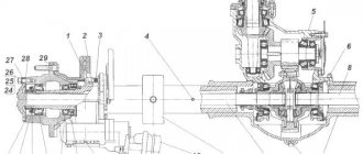
Rice. 2. Cross section of the engine: 1— oil pump; 2 — cylinder block; 3 - piston; 4 — head gasket; 5 – exhaust gas pipeline; b — block head cover; 7 — rocker arm; 8 — block head; 9 — rocker rod; 10 — centrifugal oil purification filter; 11 — carburetor; 12 — ignition distributor drive; 13 — inlet pipeline; 14 — ignition distributor; 15 — oil level indicator; 16 - candle; 17 — spark plug shield; 18 — pusher; 19 — starter current; 20 — starter; 21 — oil pan; 22 — oil pan
Rice. 3. Sequence of tightening the cylinder head bolts
The outer surface of the lower compression ring is made conical; the larger base of the cone faces down. Compression rings are installed so that the groove on the inner cylindrical surface of the rings faces upward, as shown in Fig. 4. The oil scraper ring consists of two flat steel rings and two expanders - axial and radial.
When installing a piston into an engine cylinder, flat ring discs must be installed so that their locks are located at an angle of 180° to one another. In this case, the locks of the axial and radial expanders should be located (each) at an angle of 120” to them.
In a free state, piston rings have a complex shape that allows for the most favorable distribution of ring pressure on the liner wall, which increases the service life of the ring. When installing rings on the piston, their joints (locks) must be located at an angle of 90° to one another. The design and manufacturing technology of piston rings for ZIL engines, with timely vehicle maintenance, ensures that the engine will operate until it is overhauled without changing the rings. Premature and unreasonable replacement of piston rings leads to a reduction in Engine life. Before deciding to replace the piston rings or submit the engine for a major overhaul, it is necessary to eliminate all external oil leaks, wash the filter of the crankcase ventilation system, and also clean the tube and valve of deposits and monitor oil consumption for waste.
If it is necessary to replace the piston rings or send the engine for major repairs, you should use special diagnostic equipment (compressometer, K69-A device, etc.).
To increase the service life of the engine, you should use the grades of fuel and engine oil recommended by the manual, promptly wash the filter elements of the air filter and crankcase ventilation filter, and also clean the tube, crankcase ventilation valve, and centrifugal oil purifier.
The connecting rods are steel, I-section. Thin-walled steel-aluminum liners with a thickness of 21o!o22 mm are installed in the lower head of the connecting rod. A bronze bushing is pressed into the upper head of the connecting rod.
The liners are manufactured with high precision and do not require scraping, filing joints or using gaskets during installation. These operations are not allowed for thin-walled liners.
When installing a piston and connecting rod assembly onto an engine, the arrow on the bottom must always face the front end of the crankshaft. In the piston-connecting rod assembly intended for the left group of cylinders, mark 11 on the connecting rod rod and arrow 8 on the piston bottom should face the same direction, and in the kit for the right group of cylinders - in different directions.
The nuts of the connecting rod bolts must be tightened with a torque wrench; the tightening torque is 56-62 Nm (5.6-6.2 kgf-m). It is necessary to check and, if necessary, tighten the connecting rod bolt nuts every time you remove the oil pan.
The crankshaft is steel, with hardened journals, five-bearing, with lubrication channels (Fig. 5) and cavities for oil purification. The cavities are closed with plugs with internal hex keys. The tightening torque of the plugs must be at least 30 Nm (3 kgfm). The plug may protrude from the shaft no more than the height of the chamfer. The cavities should be cleaned after 100,000 km, when replacing connecting rod and main bearings, as well as when repairing the engine.
Rice. 4. Piston with connecting rod: 1 - annular disk of the oil scraper ring; 2 — axial expander; 3 — radial expander; 4 — lower and middle compression rings; 5 — upper compression ring; 6 — retaining ring; 7 — piston pin; 8 — arrow on the piston bottom; 9 - piston; 10 — connecting rod; 11 — mark on the connecting rod rod; 12 — boss on the connecting rod cover
Rice. 5. Crankshaft: 1 - counterweight; 2—prsbka; 3 - cavity for centrifugal oil purification
The main bearing cap bolts must be tightened with a torque wrench. The tightening torque should be 110–113 N • m (11–13 kgf • m). The main bearing cap bolts must be checked and, if necessary, tightened each time the oil pan is removed. When the connecting rod or main bearing shells wear out, be sure to replace both halves of the shells at the same time. On the front main journal, in the groove of the cylinder block, two steel-aluminum thrust washers are installed in the form of two half rings, protecting the shaft from axial movements,
The crankshaft is dynamically balanced in the flywheel and clutch assembly. The tightening torque of the flywheel mounting bolts on the crankshaft flange should be 140-150 N • m (14-15 kgf • m).
The flywheel is cast iron, with a steel ring gear for starting the engine from the starter, attached to the flange of the rear end of the crankshaft with six bolts. When assembling the flywheel with the crankshaft, you must keep in mind that one of the flywheel mounting holes is offset by 2°. When attaching the flywheel to the crankshaft flange, tighten the nuts evenly. It is necessary to ensure that the flywheel mounting bolts are carefully aligned. The cotter pin should fit snugly around the end of the bolt.
The camshaft is made of steel, with hardened cams and an ignition distributor drive gear, driven by a pair of gears. The camshaft is mounted on five supports equipped with bushings made of bimetallic tape. For correct mutual installation of the gears of the crankshaft and camshaft, you need to place them so that the marks are on the same straight line connecting the centers.
The valves are upper, located in the cylinder head in one row, inclined to the cylinder axis, driven by the camshaft through rods, pushers and rocker arms. The valves are made of heat-resistant steel; the angle of the working chamfer of the intake valve seat is 30°, exhaust 45°; The exhaust valve stem has a hole filled with sodium.
Rice. 6. Position of marks on gears when setting valve timing
To increase their service life, the exhaust valves are forcibly turned during engine operation by a special mechanism. The mechanism for turning the exhaust valve is shown in Fig. 7.
If knocking occurs in the valve mechanism, it is necessary to check and, if necessary, adjust the gaps between the valves and rocker arms, which should be within 0.25-0.3 mm (for intake and exhaust valves). The clearances in the valve mechanism are adjusted on a cold engine using an adjusting screw with a lock nut located in the short arm of the rocker arm.
To adjust the clearance in the valve mechanism, you need to set the piston of the first cylinder to the top dead center (TDC) of the compression stroke. In this case, the hole on the crankshaft pulley should be located under the “TDC” mark on the ignition timing indicator located on the crankshaft maximum speed limiter sensor.
Rice. 7. Mechanism for turning the exhaust valve: 1 - valve; 2 - fixed body; 3 - ball; 4 - thrust washer; 5 — lock ring; 6 — valve spring; 7 — valve spring plate; 8 — valve block; 9 — disk spring mechanism; 10 — return spring; 11—filler; 12 - surfacing; 13 - plug
Long-term operation of the engine with incorrect clearances can lead to premature wear of valve train parts, burnt valves, wear of rocker arms, bearing surfaces of pushrods and camshaft cams.
Whenever disassembling an engine that has traveled more than 70 thousand km, it is necessary to check the condition of the return springs and balls of the mechanism for turning the exhaust valve.
If signs of wear are found on the coils of the spring, the spring must be turned with the worn area down. When assembling the mechanism for turning the valve, you need to pay attention to the correct installation of balls and springs; the springs must be located behind the ball relative to the selected direction of rotation.
Valve pushers are steel, hollow. To increase the reliability of the cam-pusher pair, special cast iron is melted onto the end of the pusher. There are holes drilled in the bottom of the pusher for lubrication.
The intake pipeline is made of aluminum alloy, common to both rows of cylinders, located between the cylinder heads and equipped with a liquid cavity for heating the mixture. The tightening torque of the nuts securing the intake pipe to the cylinder head should be within 15-20 Nm (1.5-2 kgfm). The nuts must be tightened evenly, sequentially, crosswise.
The exhaust gas pipelines are cast iron, one on each side of the block.
Wiring diagram ZIL 131
Designation
1 - Headlight; 2 — Front light; 3 - Side turn signal repeater; 4 - Generator; 5 — Engine compartment lamp PD308A; 6 — Emergency vibrator RS 331; 7 - Spark plug; 8 - Sensor for warning lamp of emergency overheating TM102; 9 — Distributor breaker; 10 — Coolant temperature sensor TM100V; 11 - Electrical signal S311-01; 12 - RS502 starter relay; 13 — ST2A starter; 14 - Voltage regulator PP132K; 15 — Transistor switch TK200-01; 16 — Ignition coil B118; 17 — Additional resistor CE326; 13 — Radio interference filter FR82F; 19 — Capacitor filter FR132T; 20 — Relay for turning on the front axle RS523; 21 — Buzzer RS 508; 22 — Radio socket V47K; 23 - Heater electric motor 192.3730; 24 — Capacitor of the heater electric motor KBP-S125-40-1.0; 25 — Resistor of the electric motor of the heater SE300; 26 - Switch 46.3710 for forced shutdown of the front axle; 27 - Switch for controlled headlight P20-A2; 28 — Heater switch P20-A2; 29 — Switch for controlled headlight VK38-B; 30 — Electric motor of the ME11 fan; 31 — Fan switch VK26-A2; 32 - MM 124-D sensors for emergency air loss in the brake system; 33 — Brake signal switch VK13-V; 34 - Turn signal relay RS57; 35 - Fuse 20A PR2B; 36 - Fuse 6A PR119-01 ; 37 — Turn signal switch P105A-01; 38 — Headlight switch P53B; 39 - Fuses (2x7.5A) 13.3722; 40 — Searchlight finder 17.3711; 41 — Battery 6ST-90EM; 42 — Cabin light FP12-B (additional); 43 — Switch for additional cabin lighting VK26-A2; 44 — Turning off the identification lights of the VK26-A2 road train; 45 — Switch for fuel gauge level sensors P20-A2; 46 — Lamp switch VK26-A2; 47 — Central light switch P44-A; 48 — Instrument panel; 49 — Pressure gauge for the brake system MD213; 50 — Instrument illumination lamp; 51 — Indicator lamp for turning on the front axle drive PP6-B; 52 - Coolant temperature gauge; 53 — Instrument cluster KP205; 54 - Ammeter; 55 — Indicator lamp for high beam headlights PD20-D1; 56 — Speedometer SP201A; 57 — Pressure gauge for tire pressure regulation system MD223-B; 58 — Ignition switch VK350; 59 — Signal button; 60 - Electrical signal contact device; 61 — Fuel level indicator sensor BM117D; 62 — Lamp PK201A; 63 — Identification lights of the UP101-01 road train; 64 - Indicator lamp PD20-E for emergency drop in air pressure in the brake system; 65 - Indicator lamp PD20-E1 for emergency drop in oil pressure; 66 - Engine oil pressure gauge; 67 — Fuel level indicator in the tank; 68 - Socket for portable lamp B47K; 69 — Indicator lamp for direction indicators PD20-D1; 70 — Warning lamp for emergency overheating of liquid in the PD20-D1 engine cooling system; 71 — Electromagnet 1402.3747 valve of the front axle activation system; 72 — Front axle switch VK403; 73 — Switch for the front axle warning lamp VK403; 74 — Driver signal switch VK38-B; 75 — Battery switch VK138B; 76 — Rear light FP133A; 77 — PS400 portable lamp socket; 78 — Trailer socket PS3OOA-YuO; 79 — License plate light FP134;
p, blockquote 12,0,0,0,0 —> p, blockquote 13,0,0,0,1 —>
We will be glad if you share your experience in repairing ZIL (replacing fuses and relays) in the comments.
Source
Pikirler: 42
Subscribe to the channel! Share the video with your friends! Thank you in advance. **** Please be understanding about advertising in my videos, without YouTube advertising, all videos disappear from searches into the very depths of the Internet. **** In this video I talk about how to adjust valves on a ZIL 130, this method is also suitable for most of the domestic automobile industry. **** Auto parts and accessories: oemzip.ru ****
Darkhan Alimkhanov
Zhyl Buryn
Please tell me, should the valves be adjusted to cold or hot?
Hello ! After grinding the head and replacing the gasket and cover, after 1-2 thousand km is it advisable to re-tighten the head?
Good afternoon Can't set the ignition?
If the valves are clamped, the car will not start or will there be contractions in any case or not?
After each cylinder at 90 degrees, I correctly understood that the gap in and out is 0.30
Sergey Meshcheryakov
Zhyl Buryn
Sergey Meshcheryakov
Zhyl Buryn
We have to do everything ourselves, thank you for at least showing us, otherwise there’s nowhere to look
Sergey Meshcheryakov
Zhyl Buryn
Maybe the oil is not flowing well to the rocker arms, the channels are probably clogged because if they let you change the oil once a year, then that’s good, a slave in the Ministry of Emergency Situations
Sergey Meshcheryakov
Zhyl Buryn
Could something have gotten out of place after assembly?
Sergey Meshcheryakov
Zhyl Buryn
I adjusted the valves as you showed, they were knocking, I tapped the rocker arms a lot with a hammer, on some cylinders the gap was off, before that the heads were removed
Hello! Sergey, can you please tell me how much the screw gap should be under gas?
Sergey Samarsky
2 zhyl buryn
Greetings! You can leave it as it should be 0.25-0.30 mm. Or you can add a gap of 0.30 - 0.35 mm. On gas, the most important thing is not to lean the mixture, i.e. it is necessary to increase the amount of gas in the fuel mixture. Let the gas consumption be a little more, but the valves will remain intact.
Hello! Sergey, can you please tell me how much the screw gap should be under gas?
you will never see a video in two approaches, before filming it you need to read the primer, and you need to know not the order of operation of the cylinders, but the operation of the camshaft, and judging by the numerous videos with valve adjustment, in modern brains the entries from the primer do not fit, so it will be Rotate 90 degrees all your life.