A modern car is a complex system of components and mechanisms that must interact smoothly. The ignition system (IS) is responsible for the start and uninterrupted operation of the internal combustion engine. The article discusses the principle of operation, types of SZ, main malfunctions, provides an ignition diagram for the ZIL 130, and provides step-by-step instructions for setting the ignition timing.
Operating principle of SZ
The safety zone of any internal combustion engine is designed to ignite the fuel assemblies in the cylinders. The mixture ignites due to the appearance of a spark that enters the contact of the candle. A spark plug is located in each cylinder. The candles work in a strict order at a given time. The efficient operation of the engine depends not only on the occurrence of a spark, but also on the strength of its current, which is also one of the functions of the spark protection system.
The vehicle's power source is a rechargeable battery, which produces a current of a certain strength. The voltage supplied from the battery is not enough to ignite the combustible mixture. The solution to this problem is entrusted to SZ. It increases the voltage supplied from the battery and supplies it at the right time to a specific spark plug. The incoming current is sufficient to create a spark that can ignite the fuel assembly.
The main stages of any SZ:
- accumulation of the required charge;
- conversion of low-voltage current to high-voltage;
- charge distribution;
- spark formation on spark plugs;
- ignition of a flammable mixture.
The following requirements are imposed on the SZ:
- Apply a spark at the time specified by the settings of the gas distribution system to the spark plug of a specific cylinder. The operation of the cylinders must be synchronized, then the engine will operate stably.
- A spark should appear in the spark plug with an accuracy of tenths of a second at the moment specified by the system settings. This is set in the settings. In other words, if the spark forms just a second earlier or later, the car will not start.
- To obtain the required spark power, the spark plug must be configured in such a way as to ignite the fuel assembly with a certain density and specific proportions of fuel and air.
- Ensure reliable operation of the engine, the functioning of which begins with the formation of a spark and ignition of the fuel mixture.
To understand how the engine works, you need to understand the operation of the SZ (the author of the video is Alexander Krupko).
Advice from the experts
Before adjusting the ignition on a ZIL 130 truck, you need to consider the following recommendations:
- The ignition system must not be left running while the engine is running.
- The switch does not need to be disassembled.
- The wires connected to the switching mechanism must not be swapped.
- Spark plugs must operate with the correct gap set.
- It is necessary to ensure that the battery is turned on correctly.
Compliance with these rules will help you adjust and configure the ignition operation as carefully as possible, without risking harm to internal systems.
Types of ignition systems
There are three types of ignition systems:
- Contact. It is outdated and found on old domestic vehicles. A mechanical device – a breaker-distributor – controls and distributes electricity in it. A more modern version of the contact system has become the contact transistor SZ. The innovation in it is the use of a transient commutator in the primary circuit of the coil.
- Contactless. In this system, also called transistor, charge accumulation is controlled by a transistor switch (electromagnetic generator of electrical pulses), which interacts with a contactless pulse regulator. The switch in this system plays the role of a breaker. The high voltage current is distributed by a mechanical breaker.
- Electronic. Controls the process of the ECU. In early versions of this system, the ECU controlled not only the SZ, but also the fuel injection system. In the latest versions, the engine management system controls the ignition.
Photo gallery
1. Details of non-contact SZ
2. Elements of electronic SZ
Contact
Contact SZ (KSZ) is the oldest, but is still widespread due to the large number of old cars. Its main advantage is reliability. Thanks to its simple design, there are few malfunctions in it, and therefore it rarely fails. And repairing the components and mechanisms of the system is very cheap and doable on your own.
KSZ consists of the following components:
- power source (battery);
- mechanical breaker;
- distributor;
- coils;
- castle;
- candles.
The operating principle is simple. Voltage is supplied from the power source, which, passing through the coil, is converted into high-voltage current. When the contacts open, a spark is generated. This should clearly coincide with the moment when the compression stroke in the cylinder ends. The resulting spark ignites the fuel assembly.
The peculiarity of the system is that it works through contacts. This is also its disadvantage, since mechanical parts wear out and sparking deteriorates.
Contactless
Modern machines are mostly equipped with non-contact SZ (BSZ). This system has advantages over the previous one, since it does not depend on opening contacts. The resulting spark has great power. The main element of the BSZ is a transistor switch, working in tandem with a special sensor.
The electromagnetic generator ensures stable operation and supply of electricity to all components. Thanks to its operation, the engine produces more thrust and saves fuel. Independence from the operation of the contact group guarantees high-quality sparking.
The advantage of BSZ is ease of maintenance. In order for the system to work stably and for a long time, you need to regularly lubricate the shaft in the distributor. Service should be performed every 10 thousand km. The disadvantage is that repairs are difficult. To identify faults, you need to have special diagnostic equipment, so you won’t be able to repair the BSZ yourself.
Electronic
This system is installed on most modern foreign cars. There are no mechanical moving parts, so there are no problems with oxidation of contacts and interruptions in sparking. The operation of the system is controlled by the unit using special sensors; a distributor with a hall sensor is used.
Thanks to electronics, the formation and supply of a spark to the cylinders is carried out with greater accuracy and reliability than with previous SZ. Due to this, the power of the power unit increases, its performance improves, and fuel consumption decreases. The components included in the SZ are highly reliable.
In electronic SZ it is easier to adjust the mating angle, the current is more stable. Almost all of the working mixture in the cylinders burns, which increases the purity of the exhaust gases. The complexity of the design makes it almost impossible to repair it yourself in the garage. Therefore, you have to contact specialized centers that are equipped with the latest equipment.
The ZIL 130 car is equipped with a transistor SZ, which simplifies its operation and repair, which should not cause problems.
Active forum discussions
What problems with the spark plugs are you talking about? When connecting the coil to the car’s ignition system, in principle, you should not have any difficulties if, during preliminary dismantling, you marked or remembered which wires are connected where. The rotor is a ring permanent magnet with four-pole cages tightly pressed to it from above and below, rigidly fixed to the sleeve. To do this, you can use an indicator screwdriver.
People who are too lazy to read the Kama Sutra and think with their heads often ask the question: “Then why is there a mark on the crankshaft pulley, if not for a strobe light? Switch The switch is designed to provide a powerful impulse regardless of engine crankshaft speed, thereby facilitating ignition of the fuel mixture. The capacitor in the breaker is no longer needed; it can be turned off - one less weak point. Double switches are available for all systems: with a variator, without a variator and with a Hall sensor. People who are too lazy to read the Kama Sutra and think with their heads often ask the question: “Then why is there a mark on the crankshaft pulley, if not for a strobe light? Has one output. The rotor is a ring permanent magnet with four-pole cages tightly pressed to it from above and below, rigidly fixed to the sleeve. That's all. Checking the Hall sensor and switch: 1.
Ignition system
The unnamed terminal of the coil is connected to the short-circuit terminal of the commutator and the commutator to ground. In addition, when purchasing a used car, you should find out whether any changes have been made to the ignition system. Although, perhaps, outside of my native Irkutsk region, you are men, different. The IT pulse transformer serves to speed up the turn-off of the transistor when the breaker contacts open. Return to contents Cost of replacing the ignition system As you can see, the GAS ignition system consists of many components.
Therefore, when replacing or performing repairs, you must follow safety regulations. The stator has an insulated stranded lead connected to the sensor lead. The ignition coil is of a cylindrical type; in older ignition systems the BB model was used. Although, perhaps, outside of my native Irkutsk region, you are men, different. Photos GAZ Burnout of the distributor cover often occurs due to a loose connection of the central high-voltage wire with the distributor cover.
The IT pulse transformer serves to speed up the turn-off of the transistor when the breaker contacts open. Output terminal on the primary and secondary windings; Center terminal spring; External insulation on the primary winding; Mounting bracket; External magnetic circuit and core. The reason may also be hidden in the electrical wiring: in particular, due to a damaged wire running from the switch to the ignition coil. There is also an ignition coil B. As you noticed, it looks no different from B. Some people install it; it is also suitable for GAZ, but I personally do not advise you to install it. Electrical wiring for 270 rubles. Or how to start the engine without a scooter
System diagnostics and troubleshooting
Having a contact transistor ignition system, the ZIL 130 is not immune to breakdowns. In order to carry out the necessary repairs, you need to know what malfunctions are possible, be able to detect and eliminate them.
There are several signs by which you can determine that there is a problem with the SZ:
- Problems starting the engine. In this case, the car is difficult to start or does not start the first time. When the ignition is turned on, characteristic sounds appear.
- When the engine is idling, the speed drops. You can determine the need for repairs using sensors. If the speed readings differ by more than 500 rpm, then urgent repairs are required.
- Engine response decreases and power drops. This can be determined by how the car accelerates when you press the gas pedal.
- Fuel consumption has increased. You can notice changes in fuel consumption if you know how much fuel was consumed in different speed modes.
If problems arise in the SZ on a ZIL 130 car, you need to check the flow of current. First you should check the spark production at the spark plugs. To do this, you need to connect a new spark plug to a high-voltage wire and try to start the engine. If the spark does not jump, you need to check the integrity of the wiring, the quality of connections and contacts, the presence of oxidation, excess moisture, etc.
If, after checking the circuit and troubleshooting, problems with the ignition remain, you need to trace the sparking in the reverse order. To do this, you need to follow the path from the spark plug along the high-voltage wire to the distributor contact, then to the coil, and end the path at the control unit. The check requires special knowledge and diagnostic equipment.
Checking for spark formation on the spark plugs should be done on all cylinders. If it is missing on only one of the spark plugs, then the problem should be looked for in the gap between this spark plug and the distributor. If there is no spark on any spark plug, then faults should be looked for in the outputs of the control unit and in it itself.
How to check ignition timing?
For effective operation of the SZ, it is important that the ignition is installed correctly and the advance angle is set correctly. A late arrival of a spark or too early may cause problems with the operation of the spark protection system on the car.
If the ignition is too late, the ignition procedure is difficult. In this case, the working mixture does not burn completely, and fuel consumption increases. With early ignition, fuel assemblies do not have time to enter the cylinders, as a result, engine power decreases. Therefore, you need to monitor the ignition timing so that it does not go astray.
To check the ignition timing with your own hands, you need to prepare a tester and a strobe light to diagnose the system, as well as a connection diagram according to which the test will be carried out. After the distributor drive is installed, you need to analyze the readings on diagnostic instruments.
After checking, using the drive and circuit, you can adjust the ignition timing yourself. Depending on the results obtained, you can set the ignition, making it either earlier or later. Adjustments must be made when the engine is running in different modes. To successfully adjust the ignition timing, you need to know what exactly the indicators should be. If you do not know how to set the ignition or gap correctly, it is better to entrust the adjustment to specialists.
Recent Entries
Simply, ignition coil B is intended for GAZ with a contact-transistor ignition system. Connection diagram for a new type of ignition system. People who are too lazy to read the Kama Sutra and think with their heads often ask the question: “Then why is there a mark on the crankshaft pulley, if not for a strobe light? So let everyone set priorities for themselves and decide whether to install xenon, a damn darkness of light bulbs and backlights, heated handles or something else. The TK transistor switch is fixed in the cabin, since its operating temperature range is within the limits - The switches are not interchangeable with each other. In the event of pulsed voltage increases, capacitor C2, when charged, prevents overvoltage of the transistor and the flow of a large destructive current through it.
Egnition lock. The ignition coil is of a cylindrical type; in older ignition systems the BB model was used.
The second end is connected to the next one, and in this way every last one is connected.
Distributor sensor: 1 - distributor cap; 2 - coal; 3 — cover spring; 4 - low voltage connector; 5 - weight; 6 — spring of the centrifugal machine; 7 - weight axis; 8 — thrust bearing; 9 — roller bearing; 10 - coupling; 11 — roller; 12 — octane corrector plate; 13 — body; 14 - ball bearing; 15 — vacuum regulator; 16 - stator; 17 — rotor bushing; 18 - felt; 19 — slider The device of the sensor-distributor is shown in Fig. Layout of the DC switch chip on Dio 34
Guide to setting ignition timing on ZIL 130
The ignition installation is carried out in the following order:
- First you need to unscrew the spark plug from the 1st cylinder and insert a paper plug in its place.
- Then you need to slowly turn the crankshaft until the piston of the 1st cylinder reaches TDC of the compression stroke. This moment is determined by the plug, which will pop out of the hole of the inverted candle with a pop.
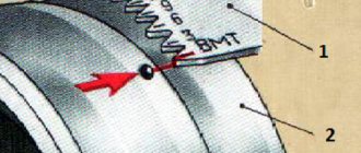
- It is necessary to ensure that the mark on the crankshaft pulley is aligned with the mark on the camshaft gear cover.
- Next you need to install the distributor drive. To do this, it must be lowered into the socket of the engine cylinder block. You need to align the holes on the plate at the bottom of the drive with the threaded holes on the cylinder block. The axis of the hole in the top plate should not deviate from the groove on the motor shaft by an angle of more than 15 degrees in any direction. The groove must be moved to the front of the power unit.
- When the drive is installed as expected, it must be secured with bolts.
- The next step is to align the mark on the pulley and the mark located between 3 and 6 combs.
- Next, use the adjusting screws to align the index arrow on the top plate of the octane corrector with the “0” position on the bottom plate. This position must be secured with nuts.
- Now the distributor-breaker in the drive should be positioned so that the vacuum regulator is located in the upper part. You can determine the location of the wire of the first cylinder, located on the cover of the breaker-distributor, by the position of the slider.
- The ignition timing is set by turning the switch by the housing until the contacts open and the 12 V pilot light comes on, which must be connected to the body ground and the low voltage terminal of the distributor. Thus, you need to catch the moment the spark is supplied to the 1st cylinder. This position of the breaker-distributor must be fixed.
- Then you should install the distributor cover, and then connect the high-voltage wires to the cylinders in series. First, the wire is connected to the 1st cylinder. The remaining wires are connected in the order in which the cylinders operate (1-5-4-2-6-3-7-8).
- Then the central wire is connected to the coil.
After completing the installation, you need to check the operation of the ignition system. If you are checking the contact SZ ignition ZIL 130 or 131, then you need to open the breaker contacts when checking. The BSZ is checked by turning the ignition on/off using the key.
If the ignition timing is set correctly, a slight detonation will be felt during acceleration of the car, which disappears when the speed reaches 40-45 km/h.
Transfer case ZIL-131 device
The ZIL-131 transfer case converts and distributes the torque received from the gearbox to the front and rear axles, and, ultimately, to the wheels of the truck.
Front-wheel drive can be activated in manual or automatic mode. The ZIL-131 transfer case also has the ability to engage a lower gear with a coefficient of 2.08 when driving in particularly difficult conditions - loose snow, muddy soil, off-road conditions. At the same time, the torque transmitted by the transfer case to the wheel drives is doubled, which makes it possible not to overload the engine and transmission units when driving in difficult road conditions.
The transfer case is two-shaft with helical gears. The transfer case body is cast from cast iron. The box design includes a back and top cover.
If necessary, a power take-off (PTO) is mounted on the upper plane of the transfer case. It serves to supply power from the car engine to various units and devices that are part of special vehicles based on ZIL-131.
Appearance of the Zil-131 transfer case:
- on top there is a cover pressed to the body with 8 nuts, covering the seat for installing the com;
- in the center is the flange of the transfer case drive shaft;
- bottom right front drive axle drive flange ZIL-131;
- at the bottom left is the pneumatic front-wheel drive activation chamber;
- on the right, at the same level with the drive flange of the transfer case, the control rods for direct and low gears.
Transfer case ZIL-131, rear view:
- at the top left you can see the control rods for turning on forward and reduced speed;
- at the top right, a cover with eight nuts covers the connection flange of the ZIL-131 power take-off;
- at the bottom right is the parking brake drum, combined with a flange for mounting the rear axle drive cardan;
- On the left is the oil filler hole of the transfer case with a tetrahedral threaded plug.
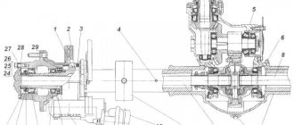
A cross-sectional view of the ZIL-131 transfer case can be seen in the illustration.
Direct (second) gear activated
The mode is designed for driving a truck on paved roads.
The RK control lever is moved to the rear extreme position. In this case, the torque from the gearbox driveshaft through the flange (9) is transmitted practically without mechanical losses from the drive shaft (15) to the secondary shaft of the rear axle drive (22). All gears of the box rotate freely. The front axle is disabled.
On dangerous sections of the road, the driver can activate the front axle drive using an electric toggle switch (switch on the control panel in the cab). At the same time, the pneumatic solenoid valve will turn on, and compressed air will enter the pneumatic chamber (8), which will push the control rod forward. The rod, in turn, moves the front axle engagement fork (32) and through the drive (21) and driven (2) direct drive gears, the gear coupling carriage (35), the torque goes to the transfer case flange (6), then to the front drive truck. The lamp on the instrument panel will light up - the drive enable indicator.
Downshifting
When driving off-road, the driver moves the transfer case control lever to the extreme forward position. In this case, the rods from the lever act on the transmission mode switching rods. The upper control rod with its fork moves the carriage (18), disconnecting the drive shaft (15) and the rear axle drive shaft (22).
The lower rod fork moves the gear carriage (37), thereby combining gears (3) and (2). At the same time, the lower rod, by pressing the microswitch located inside the transfer case, supplies voltage to the pneumatic solenoid valve. He, in turn, uses compressed air using a pneumatic chamber (8) and a fork (32) to connect the front axle drive shaft (5) with a carriage (35). Thus, the torque from the ZIL-131 gearbox through the cardan and flange (9) will go to the transfer case input shaft (15), pass through the gears (17), (3), (2) and (21), and go to the drive output shaft rear axles (22). From the gear (2) through the gear carriage (35), the torque will be transmitted through the front axle drive shaft (5) to the flange (6).