- home
- Media center
- Articles
- ZIL 130 contactless ignition circuit
Menu
- News
- Articles
- Video materials
- Photo materials
- Publication in the media
- 3D tour
13.08.2020
The internal combustion engine is the “heart” component in a car of any make and model. However, the efficiency and proper quality of operation is determined by how correctly the ignition on the ZIL performs its job. In order to cope with any malfunction in the future or diagnose it without contacting a specialized service, the ignition circuit for the ZIL 130 will help. The design includes a number of components. Each element has its own distinctive features.
Wiring diagram ZIL 131: features of the contactless ignition system
Did you like the article? Follow our channel for new ideas of useful car tips. Subscribe to us in Yandex.Zen. Subscribe.
The army version of the multi-purpose cargo ZIL 131 began military service in 1966. Many copies still work properly to this day, and not only at their combat posts, but also in the households of many enterprises and organizations in Russia.
I-Service
The engine is the heart of the car, its power and sound. In case of minor problems, you can handle it yourself. But if a serious problem arises or you don’t want to deal with all this, you can’t do without the help of specialists. In our service we will provide any assistance to your “iron friend”. We employ top-level specialists, we provide only reliable parts from trusted suppliers: original and analogues.
All prices are presented on the website and do not change. We carry out work quickly, efficiently and inexpensively. All types of services are guaranteed. They come to us again and bring friends.
Features of electrical equipment
In addition to the high off-road qualities that the 131st is endowed with, there are design features that have not previously been used in the domestic automotive industry:
- Gasoline 8-cylinder 16-valve engine;
- Contactless ignition system with electronic switch;
- Automotive alternator of increased power;
- Shielded sealed electrical wiring ZIL 131.
For reference: In case of breakdown or failure of the switch, an emergency pulse generator was installed on the car. Thanks to its presence, the car could remain in service for another 30 hours.
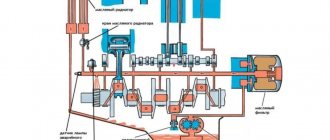
Contactless ignition system
On ZIL 131 cars, a non-contact ignition system was used for the first time, which differed from the traditional one in improved spark formation parameters:
- In the contact system, direct current from the battery passes through the primary winding of the ignition coil;
- In contactless - a capacitor is connected in the circuit between the battery and the coil;
- It stores high voltage while being charged by an electronic circuit.
In turn, the electronic circuit consists of:
- a voltage converter that charges the storage capacitor;
- an electronic key connecting this capacitor to the ignition coil.
For reference: when the spark plugs are oiled, the traditional contact ignition system is unable to ignite the air-fuel mixture in the cylinders. And the contactless one is capable of generating a larger impulse, i.e. it is less sensitive to spattering of spark plugs and to the quality of the fuel itself.
Features and disadvantages of the contactless system
The disadvantage of the contactless system in those years was the shortage of electronic components and their reliability during many years of use in harsh conditions.
In relation to ZIL 131:
- The ZIL 131 wiring was shielded, but its quality left much to be desired;
- on cars of the first years of production it was not possible to ensure the pulse duration of the capacitors;
- the design complexity of the thyristors and transistors used required additional training for auto mechanics and drivers.
Service
It is recommended to service the starter every second maintenance. Here are the operations that need to be carried out during this period:
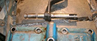
Stand check
To properly test the starter, it must first be connected to the stand without load. The verification time should not exceed one minute. If the current value does not meet the standards, the starting device will have to be disassembled.
1 – starter assembly; 2 – starter shield; 3 – starter activation relay; 4 – ignition switch; 5 – tie rod; 6 – cover from the collector side; 7 – washer; 8 – brush spring; 9 – traverse assembly; 10 – brush holder; 11, 12 – pole coil assembly; 13 – collector; 14 – anchor; 15 – bearing; 16 – washer; 17 – cup; 18, 19 – springs; 20 – guide sleeve with gear; 21 – branch sleeve; 22 – contact disk; 23 – pole screw; 24 – starter housing assembly; 25 – starter relay assembly; 26 – protective casing; 27 – gasket; 28 – lever assembly; 29 – drive side cover; 30 – liner; 31 – felt; 32 – plug; 33 – contact bolts; 34 – insulating gasket; 35 – flexible contact.
Another way is to test in idle mode. The starter is mounted on a stand, then connected to the battery. The electric motor is turned on for a maximum of 1 minute. During the test, you need to determine the rotor speed and the amount of voltage consumed - a tachometer will help. The values obtained during the test must comply with the standards. Otherwise, this will indicate interference and distortions of the shaft, as well as ametry between the rotor and the poles. But an excessively high current is evidence of a short circuit. Also, the reason for the low amplitude of rotation of the ZIL-130 starter can be a weak connection of the terminals in the electrical circuit or insufficient pressure of the brushes.
ZIL 131
Contents of the material
ALTERNATING CURRENT GENERATOR G250-I1 FOR ELECTRICAL EQUIPMENT OF ZIL-131A CAR
1 — cooling fan of the generator windings and rectifier block 2 — generator rotor shaft 3 — generator front cover 4 — stator winding insulation 5 — rotor pole pieces 6 — three-phase stator winding 7 — positive contact plate of the valves 8 — housing of the rectifier silicon diode block 9 — copper rotor contact ring 10 — end terminals of the rotor field coil winding 11 — aluminum fins of the radiator for cooling the valve block 12 — generator mounting bracket 13 — positive terminal bolt for connecting rectified (DC) current consumers 14 — ventilation window in the cover 15 — rear bearing cover 16— insulating sleeve of the contact ring 1 7 - generator brushes 18 - brush holder 19 - positive brush plug, isolated from ground 20 - ground screw (minus generator) 21 - rear cover of the generator 22 - brush holder cover 23 - brush spring 24 - fastening bolt covers 25 - terminal of the negative brush connected to ground 26 - tightening screw of the covers and stator plates 27 - outer thickened stator plate 28 - set of stator plates 29 - rotor field winding coil 30 - front bearing cover 31 - generator drive pulley 32 - negative copper contact plate of the valves 33 — screw connecting the valves to ground 34 — valve terminal with a positive potential 35 — valve terminal with a negative potential 36 — bolt of the valve block for connecting the phase terminal 37 — screw for fastening the rectifier block 38 — disk of electron-hole junction crystals 39 — silicon rectifier diode with positive potential 40 — insulating mastic 41 — diode terminal (lobe) 42 — silicon rectifier diode with negative potential 43 — brass valve base
Block of rectifying silicon diodes VBG-1
Basic data. The three-phase alternating current generator G250-I1 is designed to operate in a single-wire electrical system of automobiles with a semiconductor voltage regulator PP350-A and connecting the negative terminal to ground.
Guide to setting ignition timing on ZIL 130
The ignition installation is carried out in the following order:
- First you need to unscrew the spark plug from the 1st cylinder and insert a paper plug in its place.
- Then you need to slowly turn the crankshaft until the piston of the 1st cylinder reaches TDC of the compression stroke. This moment is determined by the plug, which will pop out of the hole of the inverted candle with a pop.
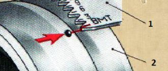
- It is necessary to ensure that the mark on the crankshaft pulley is aligned with the mark on the camshaft gear cover.
- Next you need to install the distributor drive. To do this, it must be lowered into the socket of the engine cylinder block. You need to align the holes on the plate at the bottom of the drive with the threaded holes on the cylinder block. The axis of the hole in the top plate should not deviate from the groove on the motor shaft by an angle of more than 15 degrees in any direction. The groove must be moved to the front of the power unit.
- When the drive is installed as expected, it must be secured with bolts.
- The next step is to align the mark on the pulley and the mark located between 3 and 6 combs.
- Next, use the adjusting screws to align the index arrow on the top plate of the octane corrector with the “0” position on the bottom plate. This position must be secured with nuts.
- Now the distributor-breaker in the drive should be positioned so that the vacuum regulator is located in the upper part. You can determine the location of the wire of the first cylinder, located on the cover of the breaker-distributor, by the position of the slider.
- The ignition timing is set by turning the switch by the housing until the contacts open and the 12 V pilot light comes on, which must be connected to the body ground and the low voltage terminal of the distributor. Thus, you need to catch the moment the spark is supplied to the 1st cylinder. This position of the breaker-distributor must be fixed.
- Then you should install the distributor cover, and then connect the high-voltage wires to the cylinders in series. First, the wire is connected to the 1st cylinder. The remaining wires are connected in the order in which the cylinders operate (1-5-4-2-6-3-7-8).
- Then the central wire is connected to the coil.
After completing the installation, you need to check the operation of the ignition system. If you are checking the contact SZ ignition ZIL 130 or 131, then you need to open the breaker contacts when checking. The BSZ is checked by turning the ignition on/off using the key.
If the ignition timing is set correctly, a slight detonation will be felt during acceleration of the car, which disappears when the speed reaches 40-45 km/h.
Further development of the series
For almost 20 years the car was produced unchanged. And only in 1986, a deep modernization of its platform began, caused by the need to improve its tactical and technical characteristics.
ZIL was supplied to the army and civilian organizations with:
- with a carburetor engine under the symbol ZIL 131N (modernized version);
- with diesel power unit ZIL 131N1 and N2 (of different power);
- in the civilian version - ZIL 131A in the photo below (the wiring was installed unshielded).
Off-road is also no problem for the civilian version.
Choice among analogues
The original device costs about 10 thousand rubles. The part is marked with article number ST230K4-3708000. There are also fakes, so you need to carefully inspect the starter housing for extraneous inscriptions, damage, or inconsistencies.
You can buy analogues for a much smaller amount of money. They are not very different in technical characteristics. For example, Pekar 230K43708000 can be purchased for 7 thousand rubles. But the choice of substitutes is not as wide as we would like. The Zil-130 model is outdated, which explains this fact. There is also the option of purchasing a working used product.
Source
Electrical equipment ZIL 131
Possessing off-road qualities, the “one hundred and thirty-first” was also the ancestor of some solutions that had not previously been used in the production of cargo models:
- The car was equipped with a 16-valve petrol engine with a V-shaped cylinder arrangement;
- The traditional ignition system was replaced by a contactless one with an electronic switch;
- The sealed and shielded electrical wiring of the ZIL 131 made it possible to work in the most difficult weather conditions;
All nuances were subject to thorough study.
For reference: The instructions prescribed in the event of a breakdown or failure of the electronic switch, switching to working with an emergency pulse generator. It allowed the car to remain in motion for about 30 hours.
Upgraded ignition system
In those years, a contactless ignition system appeared in the West. Despite the fact that the price of the components was high, it was considered promising and, after modification to domestic standards, they began to be serially installed on ZIL 131 vehicles.
The designers also provided for maintenance and adjustment of its components with their own hands in the field.
Despite the apparent complexity, the scheme was quite simple
Modifications
The car remained unchanged on the assembly line until 1986, when the car plant’s plans included:
- ZIL 131N - a modernized version with a carburetor engine;
- ZIL 131N1 (N2) with diesel engines;
- ZIL 131A - with a conventional wiring diagram (unshielded) for civilian customers.
Also find out all the nuances of the Niva Chevrolet wiring diagram.
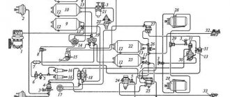
Wiring diagram ZIL 131: color with description
Since I started driving, I have become more careful when crossing the road.
It just so happens that in our country the main customer of multi-purpose transport is the army. Therefore, the appearance of the ZIL 131 truck in the ranks of the armed forces in 1966 was taken for granted.
Modification ZIL 131 – airfield tanker
Moreover, as a vehicle it has proven itself to be excellent, and some of the vehicles still regularly serve not only in army units, but also in agriculture and in the motor depots of many Russian enterprises.
Military “training” was the first to receive a detailed design of the car.
Further development of the series
For almost 20 years the car was produced unchanged. And only in 1986, a deep modernization of its platform began, caused by the need to improve its tactical and technical characteristics.
ZIL was supplied to the army and civilian organizations with:
- with a carburetor engine under the symbol ZIL 131N (modernized version);
- with diesel power unit ZIL 131N1 and N2 (of different power);
- in the civilian version - ZIL 131A in the photo below (the wiring was installed unshielded).
Off-road is also no problem for the civilian version.
How to determine the malfunction?
Problems associated with electrical equipment can be identified by the following symptoms:
- Generator: does not provide charging current, bearing noise during operation, high charging current.
- Starter: does not work; does not rotate the engine crankshaft; the rotor rotates, but does not rotate the crankshaft; when turned on, frequent clicks of the solenoid relay are heard; After starting the engine, the starter does not turn off.
- Battery: discharges quickly; The electrolyte level in the battery decreases quickly; Electrolyte spills from the ventilation holes; During charging there is a slight increase in the density of the electrolyte.
- Ignition system: the contacts in the connections of the ignition system components are broken, the power unit does not start.
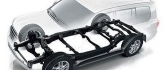
General structure of the truck
Electrical equipment ZIL 131
Possessing off-road qualities, the “one hundred and thirty-first” was also the ancestor of some solutions that had not previously been used in the production of cargo models:
- The car was equipped with a 16-valve petrol engine with a V-shaped cylinder arrangement;
- The traditional ignition system was replaced by a contactless one with an electronic switch;
- The sealed and shielded electrical wiring of the ZIL 131 made it possible to work in the most difficult weather conditions;
All nuances were subject to thorough study
For reference: The instructions prescribed that in the event of a breakdown or failure of the electronic switch, switching to working with an emergency pulse generator. It allowed the car to remain in motion for about 30 hours.
Upgraded ignition system
In those years, a contactless ignition system appeared in the West. Despite the fact that the price of the components was high, it was considered promising and, after modification to domestic standards, they began to be serially installed on ZIL 131 vehicles.
The designers also provided for maintenance and adjustment of its components with their own hands in the field.
Despite the apparent complexity, the scheme was quite simple
Service Features
In relation to the ZIL 131, the main difficulty during maintenance was the constant shortage of components and assemblies. In particular:
- ZIL 131 (shielded) wiring caused a lot of criticism due to the low quality of materials;
- Frequent capacitor failures, which forced the switch to a contact circuit;
- The abundance of electronics in the electrical circuit of the contactless ignition system made independent maintenance difficult.
In the video below you can learn about other features of this model.
We express confidence that the stated facts and presented diagrams will help in servicing this vehicle. The car itself is quite reliable and has proven this with its many years of experience in a variety of areas of work.