The KamAZ car is one of the flagships of the socialist industry, giving Soviet citizens and Russians a sense of pride. Its appearance is directly related to the rapid growth of industrial production, better known as the Kosygin reform.
It’s hard to believe, but the American automotive culture took a direct part in the creation of the people’s car of the USSR - the KamAZ 5320. How it happened and why such a successful model was produced for less than 20 years is described in this article.
Description of the KamAZ-5320 (5320) model
SPECIFICATIONS
Maud.
KamAZ-740.10, diesel, V-o6p. (90°), 8-cylinder, 120×120 mm, 10.85 l, compression ratio 17, operating order 1-5-4-2-6-3-7-8, power 154 kW (210 hp .) at 2600 rpm, torque 637 N-m (65 kgf-m) at 1500-1800 rpm. Injectors are closed type, TNDV - V-type, 8-section, spool type, with a low-pressure fuel priming pump, a fuel injection advance clutch and an all-mode speed controller. The air filter is dry, with a replaceable cardboard filter element and a clogging indicator. The engine is equipped with an electric torch device (EFD) and (optional) a pre-heater PZD-30. Transmission
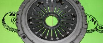
The clutch is a double-disc clutch with peripheral springs, the release drive is hydraulic with a pneumatic booster. Gearbox - 5-speed, with a front divider, total number of gears - ten forward and two reverse, gear. numbers: I-7.82 and 6.38; II-4.03 and 3.29; III-2.5 and 2.04; IV-1.53 and 1.25; V-1.0 and 0.815; ZX-7.38 and 6.02. Synchronizers - in II, III, IV and V gears. The divider is equipped with a synchronizer, the divider control is pneumomechanical, preselector. Cardan transmission - two cardan shafts. The main gear is double (conical and cylindrical), gear. number - 6.53 (ordered - 7.22; 5.94; 5.43); The middle axle is a straight axle, with a center differential locked using an electro-pneumatic or pneumatic drive.
Wheels and tires
Wheels - discless, rim 7.0-20, fastening with 5 studs. Tires - 9.00R20 (260R508), mod. I-N142B, front wheel tire pressure - 7.3; rear: KamAZ-5320 - 4.3; KamAZ-53212 - 5.3 kgf/cm 2; number of wheels 10+1.
Suspension
Dependent: front - on semi-elliptic springs with rear sliding ends, with shock absorbers; the rear is balanced, on semi-elliptical springs, with six reaction rods, the ends of the springs are sliding.
Brakes
The service brake system is with drum mechanisms (diameter 400 mm, lining width 140 mm, cam release), dual-circuit pneumatic drive. Brake chambers: front - type 24, bogies - 20/20 with spring energy accumulators. Parking brake - trolley brakes from spring energy accumulators, pneumatic drive. The spare brake is combined with the parking brake. The auxiliary brake is a motor retarder with a pneumatic drive. The trailer brake drive is combined (two- and single-drive). There is an alcohol fuse against condensate freezing.
Steering
The steering mechanism is a screw with a ball nut and a piston-rack that engages with the toothed sector of the bipod shaft, transmitting. number 20. The hydraulic booster is built-in, the oil pressure in the booster is 80-90 kgf/cm 2 .
Electrical equipment
Voltage 24 V, ac. battery 6ST-190TR or -190 TM (2 pcs.), generator set G-273 with voltage regulator YA120M, starter ST142-B.
Filling volumes and recommended operating materials Fuel tanks: for KamAZ-5320 - 175 or 250 l, for KamAZ-53212 - 250 l, diesel. fuel; cooling system (with heater) - 35 l, cool. liquid - antifreeze A-40; engine lubrication system - 26 l, summer M-10G (k) winter M-8G2 (k), all-season DV-ASZp-10V; power steering - 3.7 l, oil grade P; gearbox with divider - 12 l, TSP-15K; drive axle housings - 2×7 l, TSp-15K; hydraulic clutch release system - 0.28 l, Neva brake fluid; shock absorbers - 2×0.475 l, liquid AZh-12T; fuse against freezing of condensate in the brake drive - 0.2 l or 1.0 l, ethyl alcohol; windshield washer reservoir - 1.8 l, NIISS-4 liquid mixed with water.
Weight of units (in kg): Engine with clutch - 770, gearbox with divider - 320, driveshafts - 49 (59), front axle - 255, middle axle - 592, rear axle - 555, frame - 605 (738), body - 870 (1010), cabin assembled with equipment - 577 (603), wheel assembled with tire - 80, radiator - 25.
Use of KamAZ in army units
From the moment they entered production, KamAZ trucks also entered the formations of the USSR Armed Forces.
These vehicles received their baptism of fire at OKSVA during combat operations in Afghanistan, where they gained the reputation of being reliable and powerful vehicles, including when used in the highlands.
The main differences between the army modification of KamAZ and the civilian line were: reinforced design, a reshaped bumper, and the mandatory presence of a tire pressure regulation system. There were other differences, not so significant. The scope of use of machines in the army was quite wide:
- a vehicle for transporting bulk cargo and personnel;
- use as a platform for installing various radio equipment: command and control vehicles, launch control command posts and mobile stations for performing other tasks;
- armored vehicles for transporting personnel in the theater of military operations, this type of vehicle was not mass-produced, the armor was attached to the base model;
- vehicles for escorting convoys, gun trucks with ZU-23-3 weapons.
It’s worth talking about “gun trucks” in a little more detail; these vehicles initially had as their task the escort of convoys as they were escorted through the mountains of Afghanistan. A ZPU-4 or ZU-23-2 anti-aircraft gun was installed in the back of the vehicle.
These installations had the ability to fire all around, had an anti-aircraft elevation angle and powerful cartridges; their shells and bullets could reach the enemy at long range and altitude. This made it possible to effectively combat ambushes on the road.
The armoring of such vehicles was often makeshift and consisted of hanging the cabin doors with bulletproof vests, less often they were sheathed with metal.
The charger installation itself was covered with doors from the infantry fighting vehicle or other improvised means, the purpose of which was to protect the installation crew, although it was minimal. Subsequently, the production of such support products was suspended.
The armored Urals and KamAZs, which appeared during the Caucasian Wars and were nicknamed “Pokemons,” are also a product of handicraft production; there are practically no such vehicles in the series. Although their high efficiency in operation has been proven.
KAMAZ 5320
The KAMAZ 5320 was the first vehicle to roll off the assembly line of the plant of the same name in Naberezhnye Chelny. This flatbed tractor was produced from 1976 to 2001 and had many modifications: from a dump truck to a tanker. The car was used both in the USSR and in 40 other countries. It also became the basis for such trucks as the KAMAZ 5401 truck tractor and the KAMAZ 53212 medium-duty vehicle
Frame and fifth wheel coupling KamAZ-5320, -55102
FRAME AND FIFTH HITCH
The frame (Fig. 197) of the car is stamped, riveted, consists of two channel-section spars, variable in length, connected by cross members. At the front, the frame is equipped with a front buffer with two towing forks.
Rice. 197. Car frame: 1 - cross member 1; 2 — bracket for the front support of the power unit; 3 — cross member 2; 4 — rear engine mount bracket; 5 — right spar; 6 — bracket for the support beam of the power unit; 7 — cross member 3; 8 — cross member 4; 9 — lower gusset of cross member 5; 10 — upper gusset of cross member 5; 11 — cross member 5; 12 — rear cross member; 13 — rear cross member brace; 14 — cross member 7; 15 — cross member 6; 16 — gasket for the balancer suspension bracket; 17 — left spar; 18 — rear bracket of the front suspension; 19 — shock absorber bracket; 20 — radiator support bracket; 21-front front suspension bracket; 22 — buffer bracket
On the rear cross member of the frame of KamAZ-5320, KamAZ-53212 vehicles there is a towing device with rubber elastic elements that provide double-sided shock absorption. A rigid towing loop without a rubber shock absorber is installed on the rear cross member of the frame of KamAZ-5410, KamAZ-54112 and KamAZ-55111 vehicles, designed for towing a faulty vehicle over a short distance. It cannot be used to permanently tow a trailer.
On KAMAZ-55111, KAMAZ-53229 vehicles the towbar is installed on the rear cross member of the frame, on KAMAZ-65115 - on a subframe fixed to the rear of the frame.
KAMAZ vehicles of various models and configurations have different frames: long depending on the base; number and design of crossbars; reinforcing linings and their design; brackets and their position. Some frame samples are shown in Figure 198.
Rice. 198. KAMAZ car frames
The spars are made of low-alloy strip steel 8 mm thick. The maximum cross-section of the spar is 262x80 mm.
Cars have different frame lengths depending on the base. The frame of the KamAZ-53212 vehicle has reinforcing linings of the side members in the area of the fifth cross member.
The brackets for the power unit supports, cab supports and front suspension are connected to the frame parts with rivets and bolts with nuts.
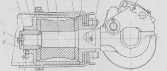
The towing device (Fig. 199) of the car consists of a hook 2, the end of which passes through the holes in the rear cross member of the frame, which has an additional reinforcement. The end of the hook is inserted into a massive cylindrical housing 15, closed on one side by a protective cap and on the other by a housing cover 16.
Rice. 199. Towing device: 1, 17 - oil nipples; 2 — hook with a dirt deflector; 3 — hook latch axis; 4 - latch pawl; 5 — pawl axis; 6 - latch; 7 - nut; 8 — lock cotter pin chain; 9—elastic element; 10—hook nut; 11—cotter pin; 12 — protective cap; 13, 14 — flanges; 15 — body; 16 — housing cover
The rubber elastic element (buffer) 9, which softens shock loads when starting a car with a trailer and when driving on uneven roads, is located between two flanges 14 and 13.
A latch is installed on the axis 3 passing through the hook, locked by a pawl 4, which prevents the trailer drawbar from disengaging with the hook.
When assembling the towbar, nut 10 must be screwed all the way into flange 13 without applying additional tightening force. After this, turning nut 10, you need to align the slots in it with the hole at the end of hook 2, and then install the cotter pin. When combining holes, axial movement of up to 0.5 mm is allowed.
During vehicle operation, nut 10 cannot be used to regulate the axial movement of hook 2, since screwing on the nut increases the axial movement of the hook.
If axial movement of the hook occurs after long-term use of the vehicle, the towbar should be disassembled and, if necessary, straightened flanges 13 and 14 and replaced worn parts.
When shrinking the rubber buffer, it is necessary to install additional ring gaskets between the flanges and the rubber buffer, then tighten the nut, tighten it and put the protective cap 12 in place.
In order to couple a tractor to a trailer you need to:
— brake the trailer with the parking brake system;
— open the towing hook lock;
— install the trailer drawbar so that the coupling eye is at the level of the car’s tow hook;
— carefully back the car until the towing hook stops in the trailer coupling eye;
— place the coupling eye on the towing hook and close the lock;
— insert the trailer plug into the car socket;
— connect the hose heads of the trailer pneumatic system with the corresponding heads of the car pneumatic system;
— connect the trailer to the car with a safety rope or chain;
— open the disconnect valves of the pneumatic drive of the trailer brake systems installed on the vehicle (single-wire or two-wire circuit);
— release the trailer using the parking brake system.
To improve maneuverability when towing a trailer, remove the rear bumpers from the vehicle.
MAINTENANCE
During daily maintenance, you should check the condition of the towbar by external inspection. Pay special attention to the presence of the latch pin.
At service 2:
— check the free axial movement of the towing device hook, which should not exceed 0.5 mm;
- lubricate the stem and nut of the towbar hook using two grease nipples;
— tighten the nuts of the bolts securing the fuel tank brackets.
At service C:
— check the condition of the frame by external inspection. The presence of cracks and traces of corrosion on the flanges of the side members and cross members is not allowed;
— check the presence of all rivets; if missing, install a bolt and nut.
REPAIR
When repairing the frame, you need to check the tightness of the rivet joints by tapping the rivet heads with a hammer. If the rivet heads shake or move under hammer blows, they must be cut down and replaced with bolted connections. There should be no cracks in the flanges of the side members and cross members.
Check the condition of the frame paint: remove corrosion, and touch up areas with damaged paint.
When repairing the towbar, you cannot use nut 10 (see Fig. 199) to adjust the axial travel of the towing hook, since tightening and unscrewing the nut leads to an increase in the axial travel of the hook. If axial movement of the hook occurs, it is necessary to disassemble the towing device and, if necessary, straighten flanges 13 and 14 and replace worn parts.
If shrinkage of the elastic element occurs, install additional ring gaskets between the flanges and the elastic element, tighten nut 10, cotter it and replace cap 12. If the hook throat is worn to a size of more than 55 mm, replace the hook.
When assembling the device, screw nut 10 all the way into flange 13 without applying additional torque, then align the slots in the nut with the hole at the end of the towing hook and install the cotter pin. When combining holes, an axial movement of up to 0.5 mm is allowed.
The surface of the trailer hitch must be level and smooth. If a worn-out hinge is repaired by welding metal, thoroughly clean the hinge to give it a geometrically correct shape, otherwise the hinge may become jammed in the towing hook jaw and the jaw may break when turning the road train.
It is not allowed to operate a towbar with a 48 mm diameter mouth with a coupling loop made from a rod with a diameter of more than 43.9 mm.
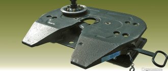
The fifth wheel coupling device (Fig. 200) of the KamAZ-5410 and KamAZ-54112 tractors serves to articulate the tractor with the semi-trailer, transfer part of the weight of the semi-trailer to the frame of the tractor and transfer traction from the tractor to the semi-trailer.
Rice. 200. Fifth wheel coupling: 1 — left jaw; 2 - latch spring; 3 - latch; 4 — locking knuckle rod; 5 — locking knuckle spring; 6- locking fist; 7 — right sponge; 8 — sponge axis; 9, 14 — oilers; 10 — release control lever; 11 — self-release safety axis; 12 — self-release fuse; 13- saddle bracket; 15 — hinge axis; 16- saddle; 17 — locking knuckle studs
The fifth wheel device provides semi-automatic coupling and uncoupling of the tractor with the semi-trailer. The coupling pins of a semi-trailer must have a journal diameter of 50.7...50.9 mm.
The fifth wheel is mounted on the fifth wheel brackets, which are bolted to the vehicle frame. Two seat brackets 13 with rubber-metal hinges are attached to these brackets. The saddle 16 is mounted on the brackets using two axes 15, which are protected from axial movement by locking plates with bolts. The saddle rotates freely in the hinges of the brackets, which ensures the longitudinal tilt of the saddle. Rubber-metal hinges can significantly reduce the dynamic loads transmitted by the semi-trailer to the tractor frame, and also provide some tilt of the saddle.
The coupling mechanism, located under the seat base plate, consists of two coupling jaws 1 and 7, a locking knuckle 6 with a rod 4 and a spring 5, a latch 8 with a spring 2, a release control lever 10 and a self-release fuse 12.
The locking fist has two positions: back - the jaws are closed, front - the jaws are open. The rod 4 of the locking cam 6 is prevented from accidentally moving to the forward position by a self-release safety device 12. After preliminary rotation of the self-release safety lock, the fist is moved to the front position by the release control lever 10 and is fixed in this position by latch 8. When the coupling pin is inserted into the mouth of the jaws (the fist is fixed by the latch in the cocked position), the latter opens and the fist, released from the latch fixation, moves and rests in the back of the head of the sponge. With further movement of the pin, the fist, under the action of spring 5, enters the groove of the jaws and thus ensures their reliable locking.
MAINTENANCE
During service 1, check the condition of the fifth wheel by external inspection.
At service 2:
— check the condition and fastening of the grip springs, locking knuckle and fifth wheel spring by external inspection;
— lubricate the fifth wheel support plate;
— lubricate the seat device through the grease nipples until fresh grease is squeezed out.
REPAIR
If the surfaces of the jaws of the coupling mechanism covering the semi-trailer pin are worn down to a hole size of 0 54 mm, replace them with new ones or restore them by welding metal, followed by processing to a size of 0 50.2... 50.4 mm.
If the surfaces of the locking knuckle in the place where the knuckle grips with the jaws of the coupling mechanism are worn down to a size of 71.5 mm, replace it with a new one or restore it by surfacing metal, followed by processing to a size of 0 73.4 ... 73.8 mm.
If the springs break, replace them with new ones.
Check the integrity of the weld at the attachment points of the locking knuckle studs with the seat and the locking knuckle rod with the locking knuckle. If necessary, weld, but the weld should not protrude above the supporting surface of the seat.
Check the fastening of the self-release safety device. When it is removed from the equilibrium position in any direction, it must return to its original position under the influence of its own weight.
TABLE 36
POSSIBLE MALFUNCTIONS OF THE FRAME AND WAYS TO ELIMINATE THEM
| Malfunction | Remedy |
| Cracks in side members and cross members | Weld the cracks. Before welding, the crack must be cut, and the ends of the crack must be drilled with a 5 mm drill. After welding the crack on the inside of the spar or cross member, weld a reinforcing strip 6...7 mm thick, and the seams should be located in the longitudinal direction |
| Bent side members or cross members | Straighten cold using jigs and jacks |
| Loosening rivet joints | Replace rivets with bolts, nuts and spring washers |
| Wear of the hook mouth is more than | Replace the hook |
Specifications
Dimensions and load capacity
KAMAZ 5320 is a truck with a payload capacity of 8 tons, while it itself weighs 7.08 tons. When fully loaded, it can also haul a trailer with a maximum weight of up to 8,000 kilograms. The maximum load of an equipped road train is 26.5 tons. In this case, 45% of the load is distributed on the front axle, and the remaining 55 on the rear axle.
In terms of its dimensions, this vehicle is slightly superior to other medium-duty trucks. The length of the body of this KamAZ is 7435 mm, and the width and height are 3350 mm and 2500 mm, respectively. The wheelbase of the car is 3190 mm, and the minimum turning radius is 9300 mm. The drawing below clearly shows the overall dimensions of this truck
Pros and cons of the car
The advantages include the following features:
- Unpretentiousness. This truck can be used in almost any climate conditions
- Low cost of both the truck itself and its spare parts
- Maintainability
- Gearbox design
- Good braking system
- A large number of modifications
On the other hand, it has the following disadvantages:
- Noisy engine
- Weak engine
- Spartan interior decoration
- High fuel consumption even after modifications to the fuel system
KAMAZ vehicles are often found on Russian roads in a variety of roles. KamAZ-5320 was the first car of this brand, marking the beginning of its history. And today you can find many 5320s in working condition on the secondary market, which are eagerly used by some carriers.
Appearance
The truck is a road train with a GKB 8350 trailer. One of the main technical characteristics of the KamAZ 5320 is its record carrying capacity. The capacity of the machine itself is 8 tons, the same amount can be transported in a trailer. Thus, the maximum permitted cargo weight for KamAZ 5320 is 16 tons.
The car body has a smooth surface. The back and side walls can be opened if necessary. This makes it possible to load and unload materials from either side. In order to protect the cargo as much as possible from any environmental influences, the body can be covered with a special protective awning during transportation.
Cabin
The car cabin is an all-metal compartment designed for three people. If necessary, it can lean forward.
For a long time, the KamAZ interior was considered one of the most comfortable compared to other trucks. This was largely due to very good noise and thermal insulation. One of the advantages of the car was the adjustable driver's seat.
The cabin is equipped with all the required instrumentation and icons, which make it possible to always be aware of the current status of the vehicle.
There is a signal system on the dashboard, where all scales and switches are clearly visible. Compared to other similar vehicles, KamAZ 5320 is the safest.
Inside the truck there is a pressure gauge with two arrows, a switch with which you can control the platform, and a sensor that reflects the number of revolutions of the power unit.
Among the disadvantages of the car is the overly large steering wheel, which takes up a lot of space in the cabin. And also the placement of the gearbox is not very convenient, which requires some practice to operate. During long trips, your legs may get tired due to uncomfortable pedals.
By modern standards, this car has a number of shortcomings. However, at the time of its appearance, it was considered the most comfortable and advanced model.
Truck history
Pre-series KamAZ-5320 and KamAZ-5410
The history of the KamAZ-5320 truck dates back to the spring of 1968, when an order was issued by the USSR Ministry of Automotive Industry on the development by ZIL specialists of a family of heavy-duty three-axle trucks and the organization of their mass production at a new enterprise.
On April 3, 1969, the Ministry of Automotive Industry issued an order according to which the Yaroslavl Motor Plant was tasked with developing four-stroke diesel engines with a capacity of 150-200 hp. for new trucks.
KamAZ-5320 being tested
The ZIL design and experimental department began developing a new promising family of trucks immediately after completing work on the gasoline ZIL-133. A number of trucks were purchased abroad to conduct tests and select the required class of hooded and hooded counterparts; the choice fell on the American International COF-220 (1962-1966) as a prototype. It is possible that when choosing a prototype, chief designer Anatoly Krieger took into account the experience of working with trucks from this company when developing the ZiS-150.
In May 1969, the first prototype of the ZIL-170 flatbed truck was manufactured, which was soon sent for testing along the Uglich-Rybinsk route. At the same time, the Central Committee of the CPSU and the Council of Ministers of the USSR adopted a Resolution on the construction of an automobile plant in the city of Naberezhnye Chelny to produce a new family of trucks.
Simultaneously with the construction of the new automobile plant, in addition to the flatbed truck, work continued on the ZIL-170T truck tractor and the ZIL-170S construction dump truck. Then all trucks were sent to undergo state tests at the Dmitrievsky test site to identify operational deficiencies.
Onboard KamAZ-5320 of the first experimental series
By the end of 1972, the identified deficiencies were eliminated if possible and the documentation, along with prototypes, was transferred to the Kama Automobile Plant. At the new enterprise, the flatbed truck was modified and received the designation KamAZ-5320 .
The development of the 8-ton GKB-8380 trailer for a flatbed truck was carried out by the Head Design Bureau, and the 15-ton flatbed semi-trailer OdAZ-9370 and the 14-ton semi-trailer van OdAZ-9770 were developed by the design department of the Odessa Automobile Assembly Plant.
The first KamAZ-5320 leaves the assembly line
On February 16, 1976, the first five KamAZ-5320 trucks were assembled. In accordance with the traditions of that time, they were decorated with the slogan “Our labor gift to the XXV Congress of the CPSU.”
The KamAZ-5320 flatbed truck was mass-produced at the Kama Automobile Plant from 1976 to 2000 and served as the basis for the creation of modifications:
- KamAZ-5410 – truck tractor;
- KamAZ-5511 – construction dump truck;
- KamAZ-55102 – agricultural dump truck;
- KamAZ-53212 – extended flatbed truck;
- KamAZ-53213 – chassis for special equipment.
This is interesting: Photo of GAZ-66: tuning, engine, frame and interior
Power unit
For the 5320 model, a V8 four-stroke diesel engine was used. Its power ranged from 180 to 210 horsepower. A spool-type high-pressure fuel pump was installed. There was also a pump that pumped up low-pressure fuel, for which a fuel injection function was provided. Another necessary device was a speed controller with several levers. The maximum value that could be achieved was 2600 rpm.
Depending on the gear ratio of the main stage, the speed of this model varied from 80 to 100 kilometers per hour. It took the car 45 seconds to accelerate from 20 km/h to 60, and 1 minute to do the same with the trailer. A full tank is designed for 1040 kilometers.
Ambient temperature does not have a strong effect on engine operation. Therefore, KamAZ 5320 can be used both at temperatures of +50 and -40 °C. The cooling system is controlled by a fluid coupling and two thermostats. It is insulated and works using antifreeze.
To prevent pollution, an automated air purification system is provided. For use in winter, the engine was equipped with a pre-heater and a torch system. The compression index is 17. For greater reliability, closed-type nozzles were used.
KamAZ 5320 has undergone several changes, thanks to which the required diesel fuel consumption has been reduced. This allowed the domestic tractor to compete with foreign vehicles. The Russian model had two fuel tanks. The volume of one of them was 250 liters, and the second - 175.
content .. 60 61 62 ..FRAME AND FIFTH-HEAD COUPLING DEVICE OF KAMAZ VEHICLES
The frame (Fig. 197) of the car is stamped, riveted, consists of two channel-section spars, variable in length, connected by cross members. At the front, the frame is equipped with a front buffer with two towing forks.
On the rear cross member of the frame of the KamAZ-5320, KamAZ-53212 vehicles there is a towing device with rubber elastic elements that provide double-sided shock absorption. A rigid towing loop without a rubber shock absorber is installed on the rear cross member of the frame of KamAZ-5410, KamAZ-54112 and KamAZ-55111 vehicles, designed for towing a faulty vehicle over a short distance. It cannot be used to permanently tow a trailer.
On KAMAZ-55111, KAMAZ-53229 vehicles the towbar is installed on the rear cross member of the frame, on KAMAZ-65115 - on a subframe fixed to the rear of the frame.
KAMAZ vehicles of various models and configurations have different frames: long depending on the base; number and design of crossbars; reinforcing linings and their design; brackets and their position. Some frame samples are shown in Figure 198.
The spars are made of low-alloy strip steel 8 mm thick. The maximum cross-section of the spar is 262x80 mm.
Cars have different frame lengths depending on the base. The frame of the KamAZ-53212 vehicle has reinforcing linings of the side members in the area of the fifth cross member.
The brackets for the power unit supports, cab supports and front suspension are connected to the frame parts with rivets and bolts with nuts.
The towing device (Fig. 199) of the car consists of a hook 2, the end of which passes through the holes in the rear cross member of the frame, which has an additional reinforcement. The end of the hook is inserted into a massive cylindrical housing 15, closed on one side by a protective cap and on the other by a housing cover 16.
Rice. 197. Car frame: 1 — cross member □ 1; 2 - bracket for the front support of the power unit; 3 - cross member □ 2; 4 — rear engine mount bracket; 5 — right spar; 6 — bracket for the support beam of the power unit; 7 — cross member □ 3; 8 — cross member □ 4; 9 — lower cross-member gusset □ 5; 10 — upper cross member gusset □ 5; 11 - cross member □ 5; 12 — rear cross member; 13 — rear cross member brace; 14 — cross member □ 7; 15 — cross member □ 6; 16 — gasket for the balancer suspension bracket; 17 — left spar; 18 — rear bracket of the front suspension; 19 — shock absorber bracket; 20 — radiator support bracket; 21-front front suspension bracket; 22 — buffer bracket
Rice. 199. Towing device: 1, 17 - oil nipples; 2 — hook with a dirt deflector; 3 — hook latch axis; 4 - latch pawl; 5 — pawl axis; 6 - latch; 7 - nut; 8 — lock cotter pin chain; 9—elastic element; 10—hook nut; 11—cotter pin; 12 — protective cap; 13, 14 — flanges; 15 — body; 16 — housing cover
The rubber elastic element (buffer) 9, which softens shock loads when starting a car with a trailer and when driving on uneven roads, is located between two flanges 14 and 13.
A latch is installed on the axis 3 passing through the hook, locked by a pawl 4, which prevents the trailer drawbar from disengaging with the hook.
When assembling the towbar, nut 10 must be screwed all the way into flange 13 without applying additional tightening force. After this, turning nut 10, you need to align the slots in it with the hole at the end of hook 2, and then install the cotter pin. When combining holes, axial movement of up to 0.5 mm is allowed.
During vehicle operation, nut 10 cannot be used to regulate the axial movement of hook 2, since screwing on the nut increases the axial movement of the hook.
If axial movement of the hook occurs after long-term use of the vehicle, the towbar should be disassembled and, if necessary, straightened flanges 13 and 14 and replaced worn parts.
When shrinking the rubber buffer, it is necessary to install additional ring gaskets between the flanges and the rubber buffer, then tighten the nut, tighten it and put the protective cap 12 in place.
In order to couple a tractor to a trailer you need to:
— brake the trailer with the parking brake system;
— open the towing hook lock;
— install the trailer drawbar so that the coupling eye is at the level of the car’s tow hook;
— carefully back the car until the towing hook stops in the trailer coupling eye;
— place the coupling eye on the towing hook and close the lock;
— insert the trailer plug into the car socket;
— connect the hose heads of the trailer pneumatic system with the corresponding heads of the car pneumatic system;
— connect the trailer to the car with a safety rope or chain;
— open the disconnect valves of the pneumatic drive of the trailer brake systems installed on the vehicle (single-wire or two-wire circuit);
— release the trailer using the parking brake system.
To improve maneuverability when towing a trailer, remove the rear bumpers from the vehicle.
MAINTENANCE
During daily maintenance, you should check the condition of the towbar by external inspection. Pay special attention to the presence of the latch pin.
At service 2:
— check the free axial movement of the towing device hook, which should not exceed 0.5 mm;
- lubricate the stem and nut of the towbar hook using two grease nipples;
— tighten the nuts of the bolts securing the fuel tank brackets.
At service C:
— check the condition of the frame by external inspection. The presence of cracks and traces of corrosion on the flanges of the side members and cross members is not allowed;
— check the presence of all rivets; if missing, install a bolt and nut.
content .. 60 61 62 ..
Brakes
Each wheel of the 5320 model is equipped with a braking device. This ensures good machine response to slowdowns and sudden stops. The built-in braking devices operate via a drive mechanism. Due to the fact that a dual-circuit system operates here, it is possible to switch the rear axle to the active position when the trolley mounted at the rear is started separately.
The KamAZ 5320 onboard tractor, the technical characteristics of which were reviewed, at one time became an indispensable assistant when transporting large loads. Despite a number of disadvantages, this car is rightfully still one of the best among all domestic models.
How much does the KAMAZ 5320 frame weigh?
How much does KAMAZ weigh?
Filling oil into the KamAZ engine
Technical characteristics of KAMAZ 55111 dump truck
Installing a hub on KamAZ 5511
How to install a synchronous divider KAMAZ
START UP RUSSIAN DIESEL KAMAZ-740.10 after 23 years storing. Made in USSR.
Quick disassembly of a KAMAZ wheel
Kamaz loads ore
How to remove a spare tire (spare wheel) on a Kamaz vehicle
- Fuel system KAMAZ 43253
- KAMAZ gearbox with gear ratio divider
- How to tighten the torsion bars of a KAMAZ cab
- Where are spare parts for KAMAZ produced?
- KAMAZ 4310 for spin tires 2015
- How to adjust the ignition of KAMAZ Euro 2 video
- Repair of KAMAZ trucks Salsk
- Replacing the rear axle of KAMAZ
- Unloading KAMAZ in Chinese
- KAMAZ scow semi-trailer
- KAMAZ mustang 8×8
- TTX KAMAZ 53215
- Test drive KAMAZ 5460 video
- Diameter of KAMAZ shoe bushings
- Antifreeze pre-heater KAMAZ
Home » Video » How much does the KAMAZ 5320 frame weigh?
How much does the KAMAZ 55111 frame weigh?
How much does KAMAZ weigh?
Technical characteristics of KAMAZ 55111 dump truck
Filling oil into the KamAZ engine
Installing a hub on KamAZ 5511
Fast loading wheat in KAMAZ 55111. Fast loading wheat in KAMAZ 55111
How to install a synchronous divider KAMAZ
KamAZ-53212 with UNIC 330 manipulator
- Cummins 6 cylinder engine for KAMAZ
- Technical characteristics of the KRAZ and KAMAZ vehicles
- Spoiler for KAMAZ 5460 high cab
- Causes of engine jammed on KAMAZ
- KAMAZ four-axle military
- KAMAZ coal is how many tons
- Ratchet for KAMAZ trailer
- Engines on KAMAZ vehicles
- KAMAZ steering system
- Our tests KAMAZ 45144
- Bolt for KAMAZ crankshaft
- KAMAZ concrete mixer 4 cubic meters
- KAMAZ radiator area
- How to install washer jets on KAMAZ video
- Selling KAMAZ truck
Home » Clips » How much does the KAMAZ 55111 frame weigh?
KAMAZ frame width
Category: Car repairs
Vehicle characteristics: The dimensions of the car are as follows: length - 3258, width - 1100, height - 1493 mm. The wheelbase is 2509 mm. Ground clearance 152 mm. The car is equipped with a hybrid power unit. The 2-cylinder engine is equipped with a system that provides engine power output. There are 4 valves per cylinder. The diameter of one cylinder is 71 mm, the piston stroke is 75 mm. The engine crankshaft accelerates to 5000 rpm. Maximum torque is maintained up to 3000 rpm.
Posted by admin: at the request of Evsey
Views: 2509
Watch the VIDEO about the width of the KAMAZ frame.
Review from a car owner named Imran: The main advantage is capacity. It seats 7 people in three rows and still has room in the trunk for things. With the 3rd row of seats folded down, you can take out half an apartment. Good maneuverability and safety, thanks to the all-wheel drive. It is impossible to get stuck in snow or mud. Parking cameras, which display a picture on the display along with an indication of the trajectory of the wheels, not only help you park quickly, but also safely, since you can see whether it is a tree branch or a piece of iron pipe. Fuel consumption. I don’t at all agree with the opinion that the machine eats a lot. On the highway - 8-9 liters per hundred. For a car with such characteristics, not much at all. Continuously variable transmission, absolutely no “dips” that are felt on conventional automatic transmissions.
Original name:
Release date: 06/06/2014
Duration: 2:53
Quality: TVRip
Laughter in the topic: A robber on the street turns to a woman: “Money, madam!” Hurry up! Think about what would happen if a jet from a water gun washed away the makeup on your face!
Video instructions: KAMAZ frame width
fremto.ru
