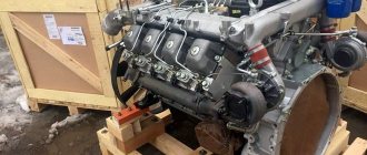
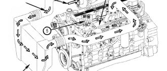
The KamAZ vehicle has a dual-circuit pneumatic braking system, which ensures vehicle safety in all driving modes. During braking (when you press the brake pedal), compressed air is immediately supplied to the brakes of all wheels. The parking brake only locks the wheels of the middle and rear axle. The main element of the drive of such a brake is the energy accumulator. KamAZ has 4 such devices - 1 for each wheel of the rear bogie.
Device
The spring accumulator is mounted on the brake chamber cover and serves to accumulate the energy of the compressed spring.
The main parts of the device are:
- cylinder;
- piston;
- power spring;
- pusher;
- thrust bearing;
- release screw with roller bearing;
- bypass tube;
- seals.
The battery is attached to the camera using bolts, which ensures a strong connection and eliminates play during operation. The seal between the cylinder and the brake chamber is ensured by installing a rubber sealing ring. A nut for the screw of the brake release system is welded in the upper part of the housing. At the bottom of the cylinder there is a threaded fitting through which the pneumatic line is connected.
A tubular pusher is welded to a metal piston with a rubber sealing ring. The steel power spring is located in the piston groove and rests on the top of the cylinder. The pusher has a thrust bearing, which transmits force to the brake chamber rod through a membrane.
The screw is used for manual release in the event of a lack of compressed air in the system due to a compressor failure or a defective receiver. At the bottom of the screw there is a roller bearing and 2 thrust rings.
The cavity located above the piston communicates with the atmosphere via a bypass tube through the brake chamber. Air is supplied to the chamber under the piston from the parking brake control valve. All energy accumulators simultaneously participate in air analysis.
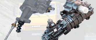
Basic design
Let's consider the device of an energy storage device. On the vast majority of modern trucks you can see brake chambers. Which are equipped with spring energy accumulators. This is a classic design, developed back in the 50s. This type of energy accumulator is considered the most reliable and durable. But the experience of using such devices in difficult conditions has revealed weaknesses - low corrosion resistance, poor protection of the mechanism from moisture and dirt, poor wear resistance of seals. All these factors do not have the best effect on the stability of the units and lead to failure of the energy storage unit.
The unit accumulates the energy of the compressed spring and, if necessary, releases it. What type of energy accumulator does the Wabco device have? Most often it is installed on the brake chambers and consists of a housing, a piston, a pusher, and a screw-axle. The spring has a fairly high power. It can release a force of about 2 tons. After this, the piston and pusher press with this force on the rod in the brake mechanism drive. When compressed air comes out from under the piston of the device (energy accumulator), holding the spring compressed, then the parking brake comes into operation. When it has worked, air again enters under the pistons.
We continue to study the design of a brake chamber with a spring energy accumulator. The screw-axis in this unit is also important. It is necessary to be able to release the brake manually. Switching off is carried out by compressing the spring. Sometimes this need for manual shutdown arises when you need to transport the machine if there is no air in the receiver due to a faulty compressor or a non-working engine.
Various models of KamAZ energy accumulators
KamAZ produces energy accumulators and brake chambers in accordance with the classification of the ratio of the membrane area and the piston area of the energy accumulator:
- 20/20
- 20/24
- 24/20
- 30/30
KamAZ 65115 is equipped with a 6520 energy accumulator model with a reinforced spring, class 30/24.
The 5320 20/20 type is also common.
Such energy accumulators ensure safety, because they are responsible for the reserve and parking brake systems, which operate when the engine is turned off and without a constant supply of compressed air.
What is the price
The price of the product depends on the modification, manufacturer and region of purchase. In the central regions of Russia, a power supply unit for KamAZ type 20/20, restored at the enterprise, can be purchased for 1500-1800 rubles. A new similar model costs from 4 to 6 thousand rubles. The price of more powerful devices of the 30/30 type ranges from 10 to 13.5 thousand rubles. If you consider that the cost of a repair kit is about 300 rubles, then it makes sense to restore failed devices.
Brake system
Modern braking systems are a complex set of control and peripheral equipment that provides emergency or smooth stopping of the vehicle and a static parking position. A pneumatic version of the system is installed on trucks and trailers. One of its elements is an energy accumulator.
Principle of operation
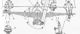
When parked, the vehicle is held in place by the rear trolley wheel braking system, which is driven by spring accumulators. The valve with the parking brake control handle is located to the right of the driver's seat. The principle of operation of the energy accumulator is simple and is based on the effect of the released energy of the power springs on the drive elements of the brake system.
When the parking brake is applied, compressed air from the bottom cavity of the accumulator cylinder is released into the atmosphere. The spring, straightening, moves the piston down. A pusher moves with it, transmitting force to the diaphragm and the brake chamber rod. The latter turns the shaft through a lever, the expansion fists of which press the brake pads against the drum, thereby locking the wheels of the rear bogie of the truck.
If the receiver or air brake circuit is damaged, air from the line escapes into the atmosphere. The released spring activates the parking brake system and locks the wheels. Further movement of the truck is possible after the wheels are released (unlocked).
Operating principle
Let's look at the design of the Kamaz energy accumulator in analysis. When the service brake system is activated, air compressed by the compressor enters the cavity above the diaphragm. The diaphragm bends under pressure and acts on the disc, moving the rod. The latter turns the adjusting lever, which actuates the expansion cam of the brake mechanism.
What is the structure and operation of the Kamaz energy accumulator? The rear and middle wheels are braked according to the same principle as the front wheels. When the driver uses the parking brake, the air that is under the piston of the device (energy accumulator) comes out. The spring relaxes and the piston moves to the right. Due to the diaphragm, the pusher acts on the rod, which moves the adjustment lever.
As a result of all actions, the car may slow down to a complete stop. When the driver releases the parking brake, air is again supplied under the piston. The latter moves to the left, the spring compresses, the rod returns to its normal position. This is how an energy storage device works.
Reviews say that if you need to brake the car in an emergency, when it is not possible to use emergency braking, you should unscrew the handbrake screws responsible for these tasks.
How to disinhibit
In order to release the truck from the parking brake, the control handle must be removed from the latch and moved to the lower position. The control compressed air is supplied via a pneumatic line through an open tap to the accelerator valve, which initiates the supply of the working medium from the receiver through the bypass valve into the lower cavity of the energy accumulator cylinder. The piston moves up and compresses the spring. The brake system rods move to their original position and release the pads. The truck is ready to move.
If there is no air in the system or the engine (compressor) breaks down and the vehicle needs to be towed, you must manually release the energy accumulator. To do this, use a socket wrench to remove the screws on the cylinders of all batteries. Thanks to the presence of a thrust bearing, the force will be transferred to the piston, which, while moving, will compress the power spring. Freed from the load, the return spring will move the diaphragm and the rod with the support disk to the upper position. The brake pad drives will return to their original state and unlock the wheels.
Situations often arise during flights when it is necessary to repair a KamAZ energy accumulator with your own hands in the field. The design of the device allows this to be done. However, it will be much easier to replace a defective energy accumulator with a working one and do the repairs in the garage.
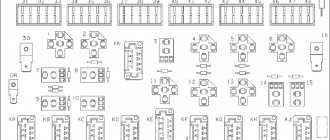
Wiring diagram of Lada Granta LADA GRANTA 21900
Click on the picture to enlarge it
1 – wiring harness block of the wiring panel to the front wiring harness block; 2 – wiring harness block of the wiring panel to the front wiring harness block; 3 – wiring harness block of the wiring panel to the rear wiring harness block; 4 – wiring harness block of the wiring panel to the rear wiring harness block; 5 – lighting control module; 6 – ignition switch; 7 – on-board computer mode switch; 8 – windshield wiper switch; 9 – instrument cluster; 10 – light signaling switch; 11 – trunk lock drive switch; 12 – diagnostic block; 13 – block of the instrument panel wiring harness to the block of the wiring harness of the air supply box; 14 – rear window heating switch; 15 – alarm switch; 16 – brake signal switch; 17 – block of the instrument panel wiring harness to the radio; 18 – block of the instrument panel wiring harness to the radio; 19 – rotating device; 20 – driver airbag module; 22 – mounting block; 23 – electric power steering; 24 – cigarette lighter; 25 – backlight lamp for the heater control panel; 26 – illuminator; 27 – block of the instrument panel wiring harness to the block of the ignition system wiring harness; 28 – controller; 29 – clutch pedal position signal switch; 30 – electronic accelerator pedal; 31 – additional resistor; 32 – heater electric motor; 33 – heater motor switch; 34 – control unit for the door lock system. K1 – relay for the electric fan of the engine cooling system; K2 – door lock relay; K3 – additional starter relay; K4 – additional relay; K5 – relay-interrupter for direction indicators and hazard warning lights; K6 – windshield wiper relay; K7 – headlight high beam relay; K8 – sound signal relay; K9 – relay for low beam headlights; K10 – relay for turning on the heated rear window; K11 – main relay;
K12 – fuel pump relay.
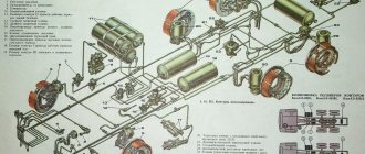
Wiring diagram of the ignition system harness LADA GRANTA 21900
Click on the picture to enlarge it
1 – oil pressure warning lamp sensor; 2 – generator; 3 – throttle pipe with electric drive; 4 – coolant temperature sensor; 5 – ignition system wiring harness block to the instrument panel harness block; 6 – solenoid valve for purge of the adsorber; 7 – speed sensor; 8 – mass air flow sensor; 9 – crankshaft position sensor; 10 – oxygen concentration sensor; 11 – controller; 12 – diagnostic oxygen concentration sensor; 13- ignition coil; 14- spark plugs; 15 – nozzles; 16 – blocks of the wiring harness of the ignition system and the wiring harness of the injectors;
17 – knock sensor.
Click on the picture to enlarge it
1 – rear wiring harness block to the instrument panel wiring harness block; 2 – rear wiring harness block to the instrument panel wiring harness block; 3 – right side direction indicator; 4 – left side direction indicator; 5 – hand brake sensor; 6 – rear window heating element; 7 – interior lamp; 8 – switch in the driver’s seat belt; 9 – trunk lighting; 10 – electric fuel pump module; 11 – right lamp; 12 – trunk locking motor; 13 – interior lamp switch; 14 - additional brake signal; 15 – left lamp; 16 – rear wiring harness block to rear left door wiring harness block; 17 – rear wiring harness block to rear right door wiring harness block; 18 – rear wiring harness block to the front right door wiring harness block; 19 – rear wiring harness block to the front left door wiring harness block; 20 – airbag control unit; 21 - rear wiring harness block to the license plate light wiring harness block.
Opinion about the material
How to remove and disassemble
To repair a faulty battery, it must be removed from its original location. To do this, you need to remove the air hoses and unscrew the 2 nuts securing the device to the base. Dismantling is carried out using a “balloon” wrench. In order to disassemble the fastening unit of the brake chamber rod and the pad drive, it is necessary to undo the cotter pin and knock out the conical wedge from its seat.
Before repairing the device, it is necessary to dismantle the bypass pipeline between the cylinder and the brake chamber. Disassembly begins by removing the bottom of the camera. It is attached to the upper body with a clamp. For safe work, the energy accumulator is installed with the cylinder down and secured in a bench vice. After dismantling the clamp, tap it on the camera body to release it from its seat.
Care must be taken when performing this work, as... under the action of the return spring, the cover may “shoot”.
The weak point of the brake chamber is the membrane. The defective item must be replaced.
Due to the low corrosion resistance of the cylinder body material, cavities and pits form on the inner surface. This is facilitated by moisture and dirt entering the glass at the top of the energy accumulator. All this leads to a violation of the tightness of the cavities and, as a result, to failure of the entire device. To eliminate the defect, it is necessary to replace the cylinder glass or try to grind the inner surface. And this leads to complete disassembly of the cylinder.
To disconnect the upper part of the battery from the camera cover, you need to unscrew the M8 bolts located around the perimeter of the case. The remaining 2 bolts will keep the cover from “shooting out” the spring. To compress the spring and unscrew the remaining fasteners, use a clamp or press. Craftsmen who carry out such repairs professionally prefer a lathe.
The cylinder is clamped into the cartridge, and the spring is compressed using the headstock. Having unscrewed the remaining bolts with the rod fully pressed, they begin to slowly remove the last one. All sealing elements are replaced with new ones from the repair kit. Reassembling the cylinder is carried out in the reverse order. The repaired device is tested on a stand by supplying compressed air. The installation of the energy accumulator in its regular place is carried out after receiving positive test results.
How to disassemble a KamAZ energy accumulator without a stand
The most convenient way to disassemble a KamAZ spring energy accumulator is to use a special stand. It is usually used at service stations and repair shops, but what to do if a breakdown occurs far from them? You can do this without a stand.
First you need to remove the air hoses and disconnect the energy accumulator from the pneumatic chamber. Further, the entire process must be carried out in strict sequence. Find videos and photos showing in detail how to disassemble can be found in the public domain on the Internet.
It is necessary to unscrew the pusher, remove the O-ring, then, slightly loosening the cylinder screw, disconnect the flange. Reinstall the cylinder and remove the retaining ring. Completely relax the spring, freeing the piston, remove it and the spring and cylinder. Remove the guide ring from the piston, unscrew the screw from the cylinder, and remove the sealing washer.
Assembly is carried out in the reverse order; parts that experience friction must be lubricated.
DO IT YOURSELF
Doing it yourself will be much faster and more profitable, because only you need it, and not a repairman. First of all, we find the cause of the breakdown of the energy accumulator and go to the store, buy the necessary spare parts and begin independent repairs.
Remove the retaining ring
Remove the top part of the energy accumulator. We leave the compressed air supply hose to remove the retaining ring inside the pusher. It is located on a bolt and holds the thrust bearing. Unscrew the thrust bearing and you will see it. To get to it, you need to supply compressed air to the energy accumulator, and then the pusher will go inside the chamber and we can get the locking ring. Another moment you need to make a hook from the electrode to hook it, look at the photo, as I did.
Hook for removing the stopper
Next, after removing the stopper, we bleed the air from the energy accumulator, remove it and disassemble it. We will disassemble it using 4 bolts with nuts, the length of which is about 12 cm. We unscrew 4 bolts from the cover of the energy accumulator, and leave 4. We will insert our long 4 bolts into these holes and tighten them with a nut. Next, we remove the other 4 small bolts and we will only have our 4 long bolts left.
4 bolts for disassembly
Slowly turning each nut, we will disassemble the energy accumulator no worse than a press, only ourselves. After disassembly, I wash all the parts and especially look at the cylinder where the piston and cuffs go, so that there are no scuffs or deep scratches there.
Malfunctions and repair of the energy accumulator
The energy accumulator plays an important role in the pneumatic drive of the brakes. The most common malfunction is system depressurization. The air hoses must be checked to determine if there is an air leak. The most likely place for such a breakdown is the connections of pipelines and hoses; more attention must be paid to them during diagnosis. If a problem occurs at the connection point, it can be eliminated by tightening the hose; if the hose itself is leaking air, then it must be replaced.
A common cause of poor brake performance is damage to the body of the energy accumulator: it may have a dent or corrosion, since the metal of the body is not wear-resistant. The cylinders begin to leak air, which leads to depressurization of the entire system. In this case, it is necessary to replace the cylinder glass.
On the Internet you can easily find videos showing step-by-step the process of dismantling and disassembling the energy accumulator, as well as troubleshooting some faults.