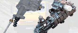
Pressure regulator KAMAZ
The pressure regulator is designed to automatically regulate pressure in the pneumatic system within the range of 0.65 0.8 MPa (6.5 8.0 KGS/SMZ), as well as to protect pneumatic drive units from contamination with oil and. excessive increase in pressure due to failure of the regulating device. The pressure regulator is connected by a pipeline directly to the compressor; attached with two bolts to the bracket.
pressure regulator
The atmospheric outlet of the regulator is directed downward so that the condensate released by the regulator does not fall on other parts of the car.
Connection and setup
The general diagram of the compressor installation shows that the pressure switch is located between the unload valve and the secondary control circuit. Most often, a pressure switch for a compressor has four threaded heads, one of which connects the device to the receiver, and the other connects a pressure gauge to monitor readings. The third can be fitted with a safety valve, and the last has a quarter-inch threaded plug in the thread. With a free connector, the user can install a control pressure gauge at his discretion.
The pressure switch is connected according to the following sequence:
- The device is connected to the unloading valve of the receiver.
- Install a control pressure gauge or plug.
- The engine control circuits are connected to the contacts.
- If there are fluctuations in the voltage network, then the connection is made through a surge filter, including when the contact power is greater than that available for the motor load current.
- If there is a need for this, the relay is adjusted through the adjustment screws to the required air pressure.
The connection is accompanied by checking that the voltage in the network matches the factory settings of the pressure switch. For example, a three-phase network of 380 Volts requires the use of a three-contact group, and for 220 Volts a two-phase group must be used.
The adjustment is made when the receiver is at least two-thirds full. The relay is disconnected from the network, the top cover is removed and the compression of the two springs is changed. The operating pressure limit is determined by an adjusting screw with an axis of larger diameter. On the board next to it there is a pressure mark in the form of the letter P and an indication of the direction of rotation of the screw, with the help of which the specified parameter is changed. The second screw helps set the required difference ΔP and has an indicator in which direction it rotates.
To speed up the adjustment process , in some cases the adjusting screw is pulled out, which changes the upper pressure level. Control is carried out according to the readings of the pressure gauge on the pressure regulator for the compressor.
Principle of operation
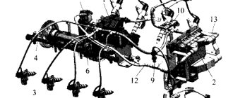
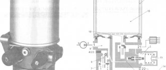
Compressed air from the compressor through terminal 1 of the regulator, filter 3, channel D and check valve 10 flows to terminal 111 and then into the air cylinders of the pneumatic drive. At the same time, through channel G, compressed air passes through cavity B under the balancing piston 9, which is acted upon by spring b. The outlet valve 4, connecting the cavity E above the unloading piston 12 with the environment through the outlet P, is open. The inlet valve 11, through which compressed air is supplied from the annular channel into the cavity E, is closed under the action of its spring in the same way as the unloading valve 2.
scheme
This state of the regulator corresponds to filling the air cylinders with compressed air from the compressor. When a certain pressure is reached in cavity B, the piston 9, overcoming the force of the spring 6, rises upward. Valve 4 closes under the action of the pusher, inlet valve 11 opens, and compressed air from the annular channel enters cavity E.
Under the influence of compressed Air, the unloading piston 12 moves down, the unloading valve 2 opens, and the compressed air from the compressor through outlet 4 exits into the environment along with the condensate accumulated in the cavity. In this case, the pressure in the annular channel drops and the check valve 10 closes. As a result, the compressor operates in unload mode without backpressure.
system pressure adjustment
When the pressure in port 3 and cavity B drops to a certain value, piston 9 moves downward under the action of spring b, Inlet valve 11 closes, and outlet valve 4 opens, communicating cavity B with the environment through pin 11. Unloading piston 12 rises upward under the action of a spring , valve 2 closes under the action of its spring, and the compressor again pumps compressed air into the cylinders.
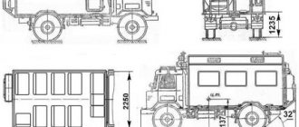
Brake systems KamAZ 6520
The brake mechanisms are a drum type system with two internal pads, the diameter of the brake drums is 420 mm, the width of the linings is 180 mm. The front brake chambers are diaphragm type 30, the rear ones are type 30/24.
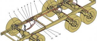
The drive of the service brake systems is pneumatic, separate. Number of receivers 6, total volume 120 liters.
Nominal pressure in the pneumatic drive (6.5-8.0 kgf/cm2).
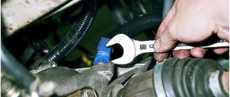
Adjust the compressed air pressure in the pneumatic drive with screw 2 of the pressure regulator (see Fig. Pressure regulator). When the screw is screwed in, the amount of adjustable pressure increases, and when turned out, it decreases.
An adsorbent air dryer 3 is installed in the vehicle's brake system (see Fig. Pressure regulator). The dryer is designed in conjunction with a pressure regulator and is designed for cooling, releasing condensate and maintaining the required pressure of compressed air supplied from the compressor. The compressed air supplied from the compressor to the dryer passes through the felt disc and granulate, is cleaned and goes further into the brake system. After the brake system is filled and the pressure regulator is activated, the granulate is cleaned of moisture by air escaping into the atmosphere through the atmospheric outlet of the dryer. Maintenance of the dryer consists of periodically replacing the filter element as it becomes dirty (about once every two years).
To inflate tires, the pressure regulator has an air bleed valve, closed with cap 1 (see Fig. Pressure regulator). When bleeding air with a hose for inflating tires from the tool kit, connect it instead of the cap, screwing the wing nut all the way, and reduce the compressed air pressure in the pneumatic drive, because when the compressor is idling, there is no air bleed. To reduce pressure, open the condensate drain valve on any receiver. Drain the condensate from the receivers daily after finishing work. The compressed air pressure in the pneumatic drive must be nominal.
Open the condensate drain taps by moving the pusher aside by the ring (see figure). Do not pull the stem down or push it up. After draining the condensate, bring the compressed air pressure in the pneumatic drive to nominal.
The vehicle's working brake systems are controlled by a two-section valve driven by a pedal.
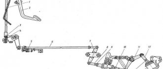
Adjust the position of the brake pedal relative to the cabin floor according to the diagram for installing the pedal on the brake valve. By adjusting the installation and adjusting bolts, it is necessary to ensure that the pedal platform is positioned at an angle of 35° ± 2° and the free play of the pedal is 10-15 mm. Secure the installation bolt with a lock nut, cover the adjusting bolt with UG7 sealant before adjustment.
The design of the pneumatic drive of the vehicle's brake mechanisms provides for the possibility of emergency release of the brakes when the handle of the control valve for the parking and spare brake systems is in a horizontal position, regardless of the degree of filling of the receivers with air. This makes it possible to start driving after the parking brake warning light goes out. It should be remembered that if there is no air in the receivers (pressure gauge readings), the service brake system does not operate and braking must be carried out using a manual brake valve. In addition, if there is no compressed air in the pneumatic system, the car can be released using the screws of the emergency brake release mechanism, which are built into the cylinders of spring energy accumulators.
Vehicles are equipped with the installation of adjusting levers with automatic adjustment of the gap in the brake mechanisms between the brake lining and the drum.
To ensure normal operation of the automatic adjustment levers, as well as after changing worn brake linings, it is necessary to make an initial adjustment of the strokes of the brake chamber rods. In the future, the need for adjustment disappears until the linings are completely worn out.
Adjusting the strokes of the brake chamber rods should be done when the brake chamber rod is in a completely released state (release the energy accumulator using the parking brake control valve) and is disconnected from the adjustment lever. Make adjustments in the following order:
- make sure that the lever is moved by hand in the direction of braking and returns completely to its original position;
- By rotating the worm of the adjusting lever, align the holes in the lever body and the brake chamber rod fork. Attach the brake chamber rod using a pin, washer and cotter pin (see Fig. Adjusting brakes with automatic levers, 1);
- press the control block of the adjusting lever all the way in the direction of its rotation in the direction of the arrow on the body (see Fig. Adjusting brakes with automatic levers, 2);
- connect the fixing bracket and the control block of the lever with a bolt and nut without disturbing the position of the control block;
- by rotating the worm of the adjusting lever, release the shoes until they come into contact with the brake drum (see Fig. Adjusting brakes with automatic levers, 3);
- turn the worm in the opposite direction approximately 3/4 of a turn (see fig. Adjusting brakes with automatic levers, 4). In this case, the characteristic operation of the gear coupling of the adjusting lever should be felt and the turning moment of the worm should be at least 42 N.m;
- make sure the lever is working. To do this, apply compressed air 5 times at a pressure of 0.b. 0.7 MPa (b. 7 kg/cm2) into the brake chamber. In this case, the lever worm should turn clockwise at a certain angle (see Fig. Adjusting brakes with automatic levers, 5);
- check that when compressed air is supplied and released, the brake chamber rod moves without jamming. The stroke of the chamber rod should be within 40.45 mm.
For a larger stroke, adjust it by rotating the worm; – make sure that when the drum is braked, it rotates evenly and freely, without touching the pads.
Vehicles can be equipped with a 4-channel anti-lock braking system (ABS) of type 4S/4M (4 sensors/4 modulators) with a microprocessor control unit from Wabco (Germany).
The main purpose of the system is to automatically maintain optimal braking of the vehicle without blocking (skidding) the wheels, regardless of what road braking occurs on - slippery or dry.
Thanks to this, cars acquire a number of advantages:
- increasing active safety by ensuring stability and controllability during braking and increasing the braking efficiency of the vehicle, especially on wet and slippery roads;
- extending tire life;
- the possibility of increasing the average safe speed.
Trouble-shooting
The cause of a brake system malfunction may be compressed air leaks in the pneumatic drive due to leaky connections of pipelines and flexible hoses. Leaks in the pneumatic drive circuits are indicated by illuminated warning lamps on the instrument panel and a buzzer. When the pressure in the circuits reaches above 450–550 kPa (4.5–5.5 kgf/cm2), the lamps should go out and at the same time the buzzer should stop sounding. The time for filling the receivers with compressed air to the nominal pressure should not exceed 8 minutes at the nominal engine speed.
Check the tightness of the pneumatic drive at the rated pressure, the compressed air consumers are turned on and the engine is not running. Locate large air leaks by ear. Minor leaks can be detected by covering the pipe connections with soap emulsion,
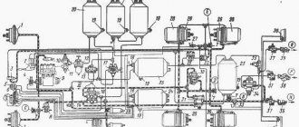
When troubleshooting, use the Diagram of the pneumatic drive of brake systems, which conventionally depicts the brake devices and pipelines connecting them.
Adjustable brakes with automatic levers
Diagram of the pneumatic drive of the brake systems of the KAMAZ-6520 vehicle
1 – brake chambers type 30; 2 – pressure gauge; 3 – auxiliary brake system control valve; 4 – pneumatic cylinder for driving the engine stop lever; 5 – pneumatic cylinder for driving the flaps of the auxiliary brake system mechanism; 6 – brake signal switch; 7 – two-section brake valve; 8,9 – pressure drop sensors; 10 – parking brake system control valve; 11 – cooler; 12 – compressor; 13 – desiccant; 14 – receiver of circuit III; 15 – receiver of circuit IV; 16 – four-circuit safety valve; 17 – main bypass valve; 18 – automatic brake force regulator; 19 – accelerator valve; 20 – receiver of circuit II; 21 – receiver of circuit I; 22 – brake chamber 30/24 with a spring energy accumulator; 23 – parking brake warning lamp; 24 – trailer brake control valve; 25,26 – automatic connecting heads (supply and control); 27 – modulators of the anti-lock braking system; B, C, D, E – control terminal valves. I – to the compressed air consumer; A – air intake valve for tire inflation
Source: www.remkam.ru
Main varieties
Check valve systems, depending on their design, can be:
- straight type;
- corner;
- spring;
- ball;
- installed using flanges;
- casement;
- mounted by soldering;
- manufactured for disassembly.
Direct type check valve for high pressure stations
The material of manufacture may also vary, depending on what environments such a device will come into contact with during operation. In particular, it can be either metal alloys of various types or plastic.
Depending on the type of shut-off element used, check valves can be:
- with a shut-off element made in the form of a flat valve;
- ball;
- membrane;
- petal;
- with gravity grid.
The last three types of devices are used for installation in ventilation systems. Among check valves and safety valves installed on compressors, ball-type devices are the most popular, since they are less critical to contaminants present in the working environment.
Check valves with cone (a), flat (b) and spherical (c) shut-off elements
Among the most modern valve systems, it is worth noting electromagnetic type devices, in which the movement of the valve is controlled not by a spring, but by an electromagnet. Meanwhile, due to the rather high cost and not too much reliability, such devices are not very popular, inferior to cheaper and time-tested spring analogues.