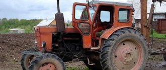
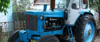
In 1961, the Lipetsk Tractor Plant mastered the production of a wheeled tractor under the designation T-40.
The successful design of the T-40 and the good technical parameters of this universal row-crop tractor helped to gain popularity, which is confirmed by its presence on the assembly line until 1995. The advantages and disadvantages of the agricultural unit model include:
- front-engine layout;
- successful design of the transmission and gearbox on the T-40;
- economical operation;
- reliability;
- maintainability.
These advantages of the T-40 helped to develop modifications that are in demand in industry and other industries. Among the main ones:
- 40AM – all-wheel drive version;
- 41AN – option with reduced ground clearance for agricultural work on slopes;
- 50A – loader with bucket;
- T38 – tracked version of the tractor;
- 40AP – modification for use in the housing and communal services sector.
Gearbox device
In the design of the T-40 tractor, a gearbox is used to change the direction of movement, select speed and perform operations. The design of the box is represented by the following elements:
- creeper;
- reverse mechanism with bevel gear;
- locking device;
- special shafts, gears with a switching mechanism;
- main gear with a differential locking device.
- Speed reducer. The device is intended, instead of a transfer case, to create an additional number of reduced speeds for the T-40, as well as to increase the number of aggregated equipment when performing various works. The creeper design consists of a gear transmission with external and internal gearing, which, when interacting with each other, form a reduced gear ratio (2.75), which is transmitted to the T-40 driven shaft.
- Reverse. A reverse mechanism with a special gear is designed to provide an additional number of speeds in the box for reversing. The design is a gearbox, the principle of which is to change the meshing gears in a bevel gear, which changes the direction and speed of movement of the driven shaft.
- Special shafts and gears, switching mechanism. Designed to obtain movement speed or change direction. The box contains input and drive shafts, as well as gears. The required gear is obtained by moving a given movable gear to engage it with a stationary one located on another shaft. The shift mechanism is designed using special shift shafts on which the forks are mounted. The shafts are moved using a shift lever, while the forks move the movable gears.
- Gear blocking device. The device is designed to prevent incomplete engagement of gears in the gearbox, as well as spontaneous disengagement. The main element is a special shaft for blocking and clamps. When the required gear is engaged, the locking shaft moves in parallel to the required gear and when the teeth match, the clamps secure the connection.
- Main gear with differential locking device. Used to transmit torque from the engine to the drive wheels, it consists of two spur gears. The differential locking device is designed to obtain the same speed of rotation of the right and left wheels of the tractor.
Gearbox of the T-40 tractor: diagram and principle of operation
The mechanism responsible for the direction and speed of movement in a tractor is its transmission or gearbox. In this article we will take a detailed look at its diagram and operating principle, and also study possible problems when working with the transmission.
Gearbox T-40
The design of the T-40 tractor includes an eight-speed (with one retarding) mechanical four-way gearbox.
its feature is the transverse arrangement of the shafts and reverse, thanks to which movement is carried out forward or backward, and also significantly increases the maneuverability, maneuverability and performance of the unit as a whole.
Model range overview
How does a manual transmission work?
The T-40 tractors were equipped with two engines D-37 (with a power of 37 horsepower) and D-144 (44 horsepower).
Modifications of tractors with D-37 engine:
- T-40 - the main model, which is equipped with rear-wheel drive;
- T-40A - all-wheel drive was installed on this tractor;
- T-40AN - a model with all-wheel drive, but with reduced overall dimensions and ground clearance to improve maneuverability on an inclined surface;
And here are the modifications of tractors with the D-144 engine:
- T-40M – standard model with rear-wheel drive;
- T-40AM – tractor with 4x4 drive;
- T-40ANM is a model with reduced ground clearance and small overall dimensions.
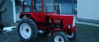
T-40 LTZ 1961-1995: technical specifications, review, description
Photo source: Bilmard.com Photo T-40
Technical characteristics of T-40, weight
| Main characteristics | |
| Weight | 2,595 kg |
| Movement speed | 2.23-26.68 km/h |
| Ground clearance | 500 mm |
| Track width | 1 200-1 800 mm |
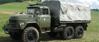
The T-40 tractor is a universal model that can be used with a wide range of attachments: a snow blade, a snow blower, a mower, a front loader bucket, etc. Also, this tractor was and is still used to this day during plowing and harvesting, during demolition of buildings and in the public sector.
T-40 modifications
A total of seven different modifications of the T-40 tractor were produced: three with the D-37 power unit, four with the D-144.
| Model name | Main characteristics |
| Modifications with D-37 engine | |
| T-40A | All-wheel drive model |
| T-40AN | Low ground clearance model for working on slopes |
| T-50A | Industrial model with loader |
| Modifications with D-144 engine | |
| T-40M | Rear wheel drive model |
| T-40AM | All-wheel drive model |
| T-40AMN | Low ground clearance model |
| T-40AP | All-wheel drive model for municipal services |
Gearbox, clutch
The T-40 is equipped with a supporting manual transmission with transverse shafts, to the crankcase of which the power unit is connected. The gearbox has a reverse mechanism, which is available for all seven gears. Another feature of the model is the installation location of the bevel gear, which is located behind the clutch.
If it is necessary to perform work at low speed, it is possible to install a creeper (mechanical or hydraulic).
A smooth start and a softer gear shift mode are ensured by the clutch of the T-40 model.
Photo source: usedauto.com.ua Photo T-40
Maintenance
Despite the fact that the T-40 tractor has not been produced for more than 20 years, the model still has fans who prefer to use this particular machine for a number of advantages.
This:
- compatibility with “attachments” originally manufactured for other brands of equipment;
- high rates of maneuverability and maneuverability on different types of soil;
- reliability, durability, ease of operation and maintenance;
- availability of spare parts.
However, the T-40 tractor also has a number of disadvantages:
- engine (air cooling of the power unit (poor heating in the cold season and insufficient cooling in the heat);
- cabin (no possibility of heating inside in winter and no cooling system in summer).
Photo source: .comThe T-40 tractor has a load-bearing manual gearbox
Specifications
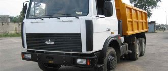
Gearbox for car GAZ-3307
The T-40 tractor is an independent technical tool controlled by the operator. Cabin capacity is one person. The device can work with any type of attachments, also suitable for earlier models (T25, T30, T35). The obvious advantage is the availability and ability to purchase a model in good condition, despite the end of production more than 20 years ago.
| Weight and dimensions of the device | The weight of the T-40 is 2595 kg. The overall dimensions of the T-40 tractor are: 3660/1620/2100 mm. |
| engine's type | Depending on the modification, the tractor can be equipped with a four-stroke air-cooled diesel engine, engine model D37 or D144. D37 has a power of 37 horsepower, D144 has a power of 50 horses. |
| Transmission | Gearbox type: seven-speed, four-way. The location of the gearbox shafts is transverse. The gearbox is located immediately behind the clutch. |
| Chassis and transmission | The transmission is mechanical, reversible type. With this part of the control system, the tractor can move freely at any speed, moving both forward and backward, without compromising productivity and productivity. The power take-off shafts are located at the rear and side and operate independently of each other in several modes. The T-40 can be equipped with a mechanical or hydrostatic type creeper. |
| Cabin | The T-40 is equipped with a fixed-type cabin with a capacity of one person. Visibility is four-way. There are rear view mirrors. The supporting system is semi-frame. |
| Tractor control | The T-40 tractor is started using an electric starter. The T-40 belongs to the 0.9 traction class. The brakes are transmission type, turning is carried out due to the movement of the front wheels. The rear wheels are on rigid suspension, the front wheels are on spring suspension. |
| Types of drive and attachments that the T-40 tractor can work with | Depending on the modification, the device can be all-wheel drive or rear-wheel drive. Works with the entire range of attachments from previous models and models identical in weight, consisting of the T-40 in the same traction class, for example, “Belarus”. The presence of pneumatic equipment is not provided. You can also connect 12-volt electrical equipment to the tractor. |
Advantages and disadvantages of the T-40 tractor
The main thing about the gearbox of the DT-75 tractor
Like any other tractors, the T-40 agricultural unit has its pros and cons.
The main advantages of an agricultural machine include:
- the highest stability and maneuverability, regardless of the type of soil;
- high maneuverability at any speed;
- free access to functionality located in the rear of the tractor;
- ease of operation;
- versatility, which consists in the ability to use any type of attachments to work with the unit;
- durability and high reliability of the tractor;
- spare parts and replacement mechanisms can be found in almost any store or market;
- presence of hydraulic power steering.
The T-40 tractor has an order of magnitude fewer disadvantages. Among them, experts highlight:
- poorly thought out cooling system of the tractor engine - because of this, the engine heats up very quickly in hot weather. Do-it-yourself modernization of the unit will help correct this factory defect;
- poor engine starting in cold weather;
- The driver's cabin does not have heating or air conditioning, which has a negative impact on comfort when working in cold and hot weather.
Despite the presence of a certain number of shortcomings, the T-40 tractor is one of the most popular units in the countries of the post-Soviet space. Reviews from tractor owners indicate its high performance, regardless of the type of work it performs.
T-40 gearbox repair
Dsg gearbox - what is it
Questions can only be asked after registration. Please login or register. Where do you need to start, the disassembly sequence, dismantling the shafts and bearings to repair the gearbox. Nobody can give an answer. Tell
It is necessary to remove the secondary shaft, how to do this? Tell.
Disassemble the entire tractor: Remove the cab, remove the space, pull out the PTO shaft, drive the secondary shaft inside, remove the gears from it and then only it will come out of the gearbox housing
In the topic I have repeatedly described everything about LTZ tractors.
“The Lipetsk tractor T-40 is the best tractor of the 20th century.” “A Russian tank is not as terrible as its drunken crew” “And there is only one warrior in the field if it is a T-40AM tractor” “Strength not supported by wisdom dies under its own weight!”
Good afternoon. Tell me where this topic is located. I can not find. Really needed!
Good afternoon. Tell me where this topic is located. I can not find. Really needed!
“The Lipetsk tractor T-40 is the best tractor of the 20th century.” “A Russian tank is not as terrible as its drunken crew” “And there is only one warrior in the field if it is a T-40AM tractor” “Strength not supported by wisdom dies under its own weight!”
Tell me how to roll out the tractor to replace the bearings on the secondary shaft, where to start, what to do with the spars, leave them on the clutch cover or on the front end, and how to put them back together.
It is necessary to remove the secondary shaft, how to do this? Tell.
Personally, I rolled out the tractor and changed the starter ring, if you have any questions, ask
will it come out in which direction??along the path of the tractor..a. to the right horseradish. two gears hold ..to the left in the reverse yoke we push further to the south. Remove the differential only to the right or to the left. who can tell?
disassemble the whole tractor down to the bolt and then pull it out
I myself encountered such a hassle and removed the spacer .. the cab wheels .. and now the side ones. I don’t know, maybe just one. remove.eh ?? dread
Guys, tell me, I didn’t take the box apart, there were no breakdowns until the rear and 4th started to turn on. In short, here it is. For some reason the switching mechanism is tilted backwards, what could be the problem?
I understand that you need to remove the top hatch? And see what's the matter?
I understand that you need to remove the top hatch? And see what's the matter?
Apparently there is something wrong with the plug, most likely broken. Lift the hatch and you will see.
“The Lipetsk tractor T-40 is the best tractor of the 20th century.” “A Russian tank is not as terrible as its drunken crew” “And there is only one warrior in the field if it is a T-40AM tractor” “Strength not supported by wisdom dies under its own weight!”
Apparently there is something wrong with the plug, most likely broken
On the T-25, when the fork was covered, the carriage began to fly back and forth while moving, then the fifth, then the first, it would fly out of the first, hit the fifth, get a kick and fly back into the 1st. It was my father who was driving then, 100 meters to the house, then he told me. I think (I think because I didn’t remove the box itself beyond the wings - I was lucky) here, like on the T-25, there is a screw-on wedge on the forks, so it may have come loose.
Pavel Vadimovich Vorobyov
The carriage generally turns easily, or there is some effort when turning.
Although what difference does it make, an autopsy will show that it won’t come off anyway.
Pavel Vadimovich Vorobyov
The carriage generally turns easily, or there is some effort when turning.
Although what difference does it make, an autopsy will show that it won’t come off anyway.
An autopsy showed that everything was much simpler, the fork stopper got twisted, thank God it wasn’t anything serious, otherwise there was already a lot of work.
The carriage generally turns easily, or there is some effort when turning. Although what difference does it make, an autopsy will show that it won’t come off anyway.
An autopsy showed that everything was much simpler, the fork stopper got twisted, thank God it wasn’t anything serious, otherwise there was already a lot of work.
And thank God. Use a knitting wire to secure it.
“The Lipetsk tractor T-40 is the best tractor of the 20th century.” “A Russian tank is not as terrible as its drunken crew” “And there is only one warrior in the field if it is a T-40AM tractor” “Strength not supported by wisdom dies under its own weight!”
The carriage generally turns easily, or there is some effort when turning. Although what difference does it make, an autopsy will show that it won’t come off anyway.
An autopsy showed that everything was much simpler, the fork stopper got twisted, thank God it wasn’t anything serious, otherwise there was already a lot of work.
And thank God. Use a knitting wire to secure it.
I understand ATP, already.
The assembly process is underway, I have to go to the agricultural machinery, when I removed the tank, the faucet broke the pancake, now I don’t know how to unscrew the rest of the thread from the faucet from the tank, the bastard is sitting well.
remove the PTO spacer and the right side panel. BUT IT IS POSSIBLE TO DO IT IF YOU KNOCK OUT BEARING 102211 TO THE LEFT WITH THE SHAFT, it’s much easier than wasting an extra day!! YES AND REMOVE!! THE CORKSCREW RING ON THE SHAFT IS MANDATORY. the photo shows that the shaft is to the left and 102211 M to the right BUT WHEN I INSERTED THE NEW BEARING IT JUMPED TO THE RIGHT AND THIS IS SUPER!! THERE WILL BE LESS HAMMORAS IN THE FUTURE!!
Causes of breakdowns and their restoration
Problem #1: Difficulty shifting gears, inaccurate shifting.
Solution: Adjust the clearances of shafts, gears and other parts. Thanks to the above features, gearbox repair has become easier, but there is a need to regularly check the clearances. This is painstaking work that requires experience. It is carried out similarly to adjusting engine clearances - using special metal feeler gauges and gaskets of different thicknesses.
Tractor gearbox diagram
Problem No. 2: Knocks out gears when working with heavy equipment (plow, blade).
Solution: Adjust the clamp and check the tightness of the fixing bolts.
Problem #3: Oil leak.
Solution: Replace the input shaft oil seal.
General repair recommendations:
- Before starting repair work, open the crankcase housing and remove the bearing cover. It is located to the left of the main shaft. Then remove the power take-off shaft cover located on the right.
- In order to remove the cup with bearings, you need to unscrew the clamping pin and the spacer sleeve.
- To remove the reverse, you need to remove the lock washer, for which you need to turn it 30°, after which it will be easy to remove the stopper from the bearing.
- The question often arises of how to remove the input shaft from the T 25 tractor. The safest way is not to knock it out, but to pull it out by screwing two bolts into the holes under the power take-off shaft.
Assembly is carried out in the reverse order, if necessary, replacing worn parts.
Service
An important operation is to check the quality, level, and service life of the lubricant in the box body. High-quality transmission oil will protect gears and shafts from premature wear and corrosion
High-quality transmission oil will protect gears and shafts from premature wear and corrosion.
It is necessary to use a lubricant with a specified temperature regime for periods of operation (summer, winter, all-season).
The frequency of checking the oil level is performed every 240 operating hours. Check the level using the control plug, which is located on the gearbox housing.
If the level is low, fill the oil to normal through the control hole. It is strictly not recommended to fill transmission fluid above the level of the control mark, as this will lead to the creation of an increased density of the oil film on the gear teeth, which causes deformation.
When changing transmission fluid, every 960 operating hours it is necessary to flush the elements and components of the box. To do this, the oil is drained from a hot engine, which allows the box to be cleared of deposits.
Also, in the T-40 gearbox, the meshing value of the gear teeth is not adjusted until the gearbox is completely inoperable.
Performing such simple operations will allow for high-quality maintenance of the gearbox and increase the service life of the multifunctional T-40.
Distinctive features of the high-speed box
The gearbox on the T 40 is mechanical, reversible. Reverse provides increased productivity and improves tractor control. The reverse includes a bevel gear, a coupling, and driven wheels. The clutch moves directly along the splines of the input shaft. The differential lock mechanism has excellent performance.
T 40 gearbox diagram
The T 40 gearbox includes a creeper. This mechanism is found on self-propelled vehicles and is an integral part of the transmission system. The main function of the creeper is to obtain low speed when moving. Also, the main elements of the transmission include shafts, gears, and a shift mechanism.
The T 40 tractor gearbox is designed for 8 speeds. Basically, TAD-17 oil is poured into the box. This fuel will protect all internal components of the box from wear, as well as the appearance of corrosion on their surface. For preventive purposes, the tractor driver should not allow prolonged idling to occur.
Gearbox T 40 disassembled
The T 40 AM tractor is an all-wheel drive model. It is one of the most popular among agricultural workers. The AM version is easy to maintain, has high cross-country ability, and provides excellent maneuverability. In order to be aware of what oil pressure is in the system, a special pressure gauge is installed in the tractor cabin.
Causes and symptoms of bearing failure in manual transmissions
Bearing units in a manual transmission perform the function of rolling bearings, therefore, if the rolling bearing is faulty, there will be difficult rotation of the elements, an imbalance will appear, as well as radial and axial runout, backlash, noise, and knocking.
- The bearing hums, the noise increases when the clutch is disengaged;
- Difficulty switching gears;
- Spontaneous transmission shutdown;
- A knocking noise is heard when pressing the clutch pedal.
- Expiration of product service life;
- Poor quality ball bearing;
- Wear or runout;
- Aggressive driving style and gear shifting;
- Insufficient amount of lubricant on the bearing or its absence;
- Dirt or abrasive particles getting inside the ball bearing;
- Malfunction of adjacent components (releaser, clutch, secondary or intermediate axle).
Read more: How many points to pump wheels in winter
After removing the axle from the axle, you need to make sure that the part is faulty. To do this, check the ease of rotation of the part, and also do a visual inspection, namely, the presence of damage to the rings, cage, as well as defects in the raceway. If the product is in good condition, it is advisable to take measurements of the axial clearance and radial clearance, as shown in the video.
Video: “How the VAZ 2107 input shaft bearing hums”
Video: “Bearing play in the input shaft of the VAZ 2107 gearbox”
Technical parameters of T-40
The versatility in use and, as a result, the popularity of the T-40 were ensured by the technical characteristics, while the speed parameters coincide with the T 150K tractor:
- Class – 0.9.
- Load capacity – 0.85 t.
- Drive – front (4x2).
- Engine – D-144: Type – diesel.
- Number of cylinders – 4.
- Cylinder volume – 4.20 l.
- Cooling is air.
- Power – 50.50 l. With.
- Length – 3.66 m.
- Mechanical.
- Weight – 2.37 t.
Gearbox of the T-40 tractor: diagram and principle of operation
The mechanism responsible for the direction and speed of movement in a tractor is its transmission or gearbox. In this article we will take a detailed look at its diagram and operating principle, and also study possible problems when working with the transmission.
Gearbox T-40
The design of the T-40 tractor includes an eight-speed (with one retarding) mechanical four-way gearbox.
its feature is the transverse arrangement of the shafts and reverse, thanks to which movement is carried out forward or backward, and also significantly increases the maneuverability, maneuverability and performance of the unit as a whole.
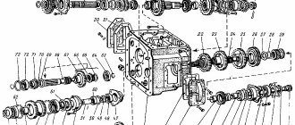
T-40 gearbox diagram
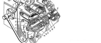
Below we present a diagram of a bevel gear with reverse for the T-40 tractor and give an explanation of its operation.
On the front wall of the housing there is a threaded and mounting hole, with the help of which the T-40 clutch housing is connected and various unit control units are installed.
The brake hoses are attached to the side walls. The rear wall is used for mounting the bracket for the suspension system levers and the rear power take-off shaft extension. The upper part is covered with a lid on which the mechanism and system of levers for controlling gear shifting, reverse and differential lock are mounted.
The primary shaft of the box is driven into rotation by the main clutch shaft using bevel gears and a T-40 reverse. The drive bevel gear (position 21) rotates in two bearings, ball (6) and roller (22).
The ball is placed in a special glass (7) and fixed along the outer ring using a nut (12) and a collar. The ring of the inner part is pressed by a nut (8) to the end of the main gear through the sleeve (23)
This design limits the axial movement of the drive gear.
Gaskets (5) are placed under the glass (7), which regulate the clearance of the conical pair hook. The drive bevel gear rotates in constant mesh with two gears (2, 13). The reverse gear or driven gear (2) is placed on two ball bearings (18, 19).
Preventing the movement of the gear along the axis is carried out using locking rings; they also fix the bearing itself (18); the gap of the gear rings (2.13) is adjusted using gaskets that are placed under the flange (3) and bolts (4). The hollow shank (2) has cut splines that transmit rotation to the shaft of the T-40 creeper and is placed in place of the cup (3)
When installing the creeper, you need to remove the gear with bearings (2) from the cup (3) and mount it into the cup of the creeper itself.
The ends of the driven gears are made with splined slots; between them, on the shaft splines, there is a coupling (20); it can move in the axial direction.
The rotation of the primary oval occurs in two ball-type bearings, one of them is located in the bore of the gearbox housing, and the second is in the bore of the right wall of the housing and is fixed by the cover of the cup and ring in the direction of the axis, which prevents any displacement along it.
Also, the drive gear of the first gear is mounted stationary on the spline of the input shaft on the right side of the gearbox. The 4th gear drive gear and two more sliding carriages are installed on the through rectangular shaft splines:
1) Drive gears of the 2nd and 3rd gears; 2) Drive gears of the 5th and 6th gears.
A spur gear is installed on the left end of the secondary shaft, which is responsible for the synchronous PTO drive. In this case, the secondary shaft rotates in two roller and ball bearings. The roller is mounted in the bore of the gearbox housing, and the ball in the bore of the right wall.
The 6th gear gear and the 2nd and 5th gears, as well as the main gear drive gear block and the 3rd gear gears are mounted on the splines of the second shaft. The following carriages are also placed on the shaft: 1) 4th gear and reverse gear;
2) 1st and slow gears.
The slow gear gear shaft is located in the lower right part of the tractor gearbox housing and its rotation is carried out in two ball bearings. A block of reverse gear wheels is also attached to it.
Also, cut gear teeth are attached to the shaft, which are in constant mesh with the intermediate gear. The axle is secured through a plate into the wall of the transmission housing of the T-40 tractor.
We looked at the T-40 gear shift diagram in one of our articles earlier.
Typical malfunctions of the GAZ-53/3307 gear selection mechanism and their elimination
The gear selection mechanism is an important part of the gearbox; any malfunctions critically affect the operation of the entire unit, so problems with this mechanism must be resolved without delay.
The gear selection mechanism has two main problems:
- ?Departure? one or more gears - usually this is a direct consequence of deformation or wear of the forks, loosening of the forks on the rods, as well as wear of the rods themselves;
- Difficulty in engaging or disengaging gears most likely occurs due to jamming of latches or other parts, and this again occurs due to deformation or wear of components.
There may also be a weakening of the reverse gear fuse, a malfunction of the reverse light switch, breakage or wear of the cotters on the forks, and a number of other malfunctions.
In any case, if the gearbox malfunctions, it should be removed from the truck, disassembled and troubleshooted. All worn, deformed or damaged parts should be replaced.
To maintain the gear selection mechanism of the GAZ-53/3307 gearbox in working condition, you should follow the recommendations for operating the transmission and perform regular maintenance of the gearbox. If you treat the gearbox with care, use the recommended gear oil and timely troubleshooting, the gearbox will work long and reliably.
Specifications
Weight and dimensions
The weight of the T-40 tractor is 2370 kg, and the T-40A model weighs 2570 kg. The weight increase is dictated by design improvements.
The overall dimensions of all modifications are similar: their length is 3660 mm, width is 1625 mm, and height is 2370 mm. Changing the track width in T-40 tractors is not provided.
Engine
The D-37 engine has a volume of 4.15 liters. The engine starts using an electric starter. The nominal speed of the motor is 1500 rpm. Cooling occurs using air.
Despite the fact that the D-144 engine has 13 horsepower more, its design is exactly the same, with the exception of volume and number of revolutions.
Box
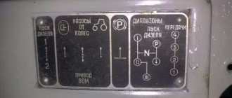
The gearbox has 14 positions. In addition to the standard 7 steps forward, there are 7 more reverse positions.
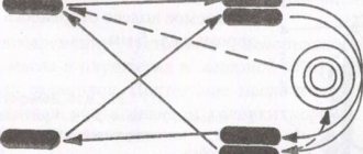
Control diagram
A distinctive feature is the number of speeds for driving in the opposite direction, since many similar models have much fewer of them. The maximum transport speed can reach 26.7 km/h.
Chassis and transmission
The T-40 tractor is mounted on a metal frame. There is a motor in front, which is connected to the gearbox and rear axle. The advantage of this model over many analogues is the transverse arrangement of the gearbox shafts. Thanks to this design solution, it was possible to position the gearbox directly behind the clutch.
It should be noted that the T-40 tractor is equipped with a combined clutch. At the rear there is a block for controlling the rear and transverse shaft. They are able to work both separately and together. The T 40 tractor is equipped with a combined mode suspension. There are shock absorbers at the front, and a rigid one at the rear. Improved cross-country ability of the T-40 tractor on country roads is achieved thanks to the special shape of the treads.
Cabin and controls
T-40 tractors do not have a very comfortable cabin, but do not forget about how much it costs. It focuses on simplicity and clarity. The visibility is not the best, mainly based on the owner's forward visibility. Climate control in the cabin is also not provided. The instrument panel provides minimal information about speed, fuel and oil quantity.
Hydraulics and drives
The hydraulic system of the Soviet T-40 tractor consists of the following components:
- Hydraulic booster;
- Distributor;
- Main and remote cylinder;
- Lubrication system;
- Three-point hitch;
- Flexible connecting hoses.
Description and design of the tractor
The T 40 AM tractor has compact dimensions, making it easy to handle small areas and can be maneuvered in a garden or greenhouse. It plows light soils and transports loads. You can install a haystack thrower on it, which simplifies the work of peasants during haymaking. In winter, this model is used to clear roads of snow. The tractor plant was tasked with creating a universal medium-power machine to perform a number of functions, as well as plow the land.
The design of the tractor is simple, but, nevertheless, it contains the following elements of electrical equipment:
- generator;
- electric starter;
- battery;
- pneumatic compressor;
- lighting;
- hydraulic system.
The T 40 tractor was very popular
Despite the fact that the T 40 tractor went into production back in Soviet times, it is still popular today due to its endurance and versatility. The machine has a number of advantages, among which are:
- the tractor runs on any type of soil and under any conditions;
- at any speed it can easily maneuver;
- used for various types of work in the agricultural industry;
- durable and reliable to use;
- Spare parts for repairs can even be bought on the market.
But despite many advantages, the T 40 also has disadvantages:
- air cooling does not cope with its functions in the summer, on days when the temperature rises above 27 degrees, which is why the engine quickly heats up;
- the engine is almost impossible to start on frosty days;
- There is no air conditioning or heating in the cabin, which creates discomfort for the driver.
Despite these shortcomings, the T 40 tractor does not lose its popularity in all countries of the post-Soviet space. It is even purchased by individual landowners for their own use due to its small size and high endurance.
If the tractor smokes
If a tractor smokes, this may be due to:
- incorrect adjustment of the working fluid supply;
- motor overload;
- incorrect installation of the piston part;
- dirty air purifier;
- small advance angle of the fuel injection system;
- damaged injectors.
In these cases, engine repair using spare parts is required, and in some situations, overhaul.
See » Review of the Belarus MTZ-92P universal tractor and its modifications
If the smoke is black, it is recommended to reduce the load on the power unit or switch to first or second gear. It is also worth checking the nozzle holes of the spray mechanism with a needle, rinsing it, and if necessary, replacing it.
When white smoke pours out, you need to grind the valves or replace the heads of the cylindrical elements. The cause of white smoke may be water getting into the diesel fuel; in this case, it is necessary to drain the fuel fluid and add new one.
Blue smoke is a sign that piston parts such as rings and liners have been damaged.
Device, diagrams, repair
Front drive axle of the T-40 tractor - design and repair
Front axle device
The front drive axle of the T-40 AM and T-40 ANM tractors is used to increase traction forces and increase cross-country ability on moist soils and in off-road conditions. The front axle consists of a transfer case, differential, main and final gears and suspension.
Diagram of the T-40 front axle: 1 - transfer case housing; 2 - plug; 3 - gear; 4, 24 — ball bearings: 5 — front cover; 6 — transfer case shaft; 7 — drive shaft of the front drive axle; 8 — main gear drive shaft; 9 - drive gear; 10 - glass; 11 — driven gear; 12 — adjusting shims; 13 - wedge; 14 — axle shaft; 15 — brake washer; 16 — bridge body; 17 — pawl axis; 18 - dog; 19 — differential housing cover; 20 — shield; 21 — final drive; 22 — front wheel suspension; 23 — cardan; 25 — splined holder; 26 — differential housing; 27 - pin; 28 - sleeve.
Front axle final drive
The main gear consists of a pair of bevel gears with a circular tooth. The drive gear is mounted in a cup on two ball bearings. The driven gear is part of the differential and is attached to the differential housing with bolts and pins.
During operation of the front axle, it is necessary to monitor the lateral clearance in the engagement of the teeth of the main gear. If noise or other malfunctions occur, it is necessary to check the mesh clearance or axial play of the drive gear. Due to tooth wear, an increase in the lateral clearance in the meshing is permissible up to 2 millimeters. If the gap increases due to wear of the bearing tracks, they must be replaced with new ones. The factory adjustment of the lateral clearance in the gear mesh is in the range of 0.17-0.65 mm.
Both gears are replaced simultaneously during operation and further development of their service life. When installing the sleeves, the total number of shims on both sides should be such that the differential rotates freely in the bearings by hand without any jamming or displacement.
Front axle differential
The differential allows the drive wheels to rotate at the same angular speed, which is required when driving the tractor over uneven terrain and when performing maneuvers.
The front drive axle differential design is a double-acting ratchet-type overrunning clutch. The differential consists of a housing, a splined race, a driven gear and a cover, connected to each other using four bolts. In the driven gear, cover and differential housing there are two axes each, on which a pawl is installed on a key. As the driven gear rotates, the pawls engage with the inner races by the frictional force that appears between the special patterns on the ends of the pawl axles and the surfaces of the brake washers.
Using springs, the axles are constantly pressed against the brake washers to create friction. Depending on the direction of rotation, the pawl engages with one of its ends. If the rear wheels rotate with less than 4% slip, the splined races overtake the driven gear, forcing the pawls to click along the teeth of the races. When the slipping of the rear wheels exceeds 4%, the forward movement of the tractor will decrease, while the driven gears and angular speeds of the cage will be leveled. With a subsequent increase in slipping of the rear wheels, the pawls will engage with the splined race, as a result of which torque will be transmitted from the driven gear through the splined races and axle shafts to the front wheels.
Rear axle repair
The rear axle structure of the T-40 tractor includes:
- gear housing;
- a flange that relates to the cardan drive;
- final drive gears;
- self-locking center differential.
During maintenance and repairs, the following must be done:
- Drain the oil fluid from the gearbox.
- Disconnect the driveshaft.
- Remove the axle shafts.
- Remove the rear wheels and brake drum mechanism.
- Unscrew the mounting bolts that connect the gearbox and rear axle.
- Remove seals, flanges, bearings and satellites.
- Inspect all parts for damage and wear.
Procedure for assembling the rear axle gearbox:
- Attach the adjusting washer to the drive gear.
- Attach the spacer, bearings and flange.
- Tighten the locknut.
- Install the driven gear into the differential housing.
- Adjust the backlash.
- Tighten all mounting nuts and bolts.
Lock repair
In order to repair the locking mechanism, you need:
- Set the gear shift knob to neutral.
- Release the main clutch pedal, i.e. the clutch must be engaged.
- Unpin the fork pin and remove it from the locking mechanism lever.
- Move the lever to its extreme position, which will correspond to the engaged clutch.
- Unscrew the plug and disconnect it from the rod.
- Adjust the locking mechanism.
- Reinstall the fork pin and secure it with a cotter pin.
In order to lubricate all the parts of this mechanism, it is necessary to spray the oil liquid over the vehicle transmission housing.
The differential lock is installed as follows:
- The tractor is installed on a special platform.
- Unscrew the wheels.
- Remove the brake drum mechanisms.
- The axle shafts, driveshaft, and gearboxes are adjusted and stretched.
- Lock and install all parts in reverse order.
Brake band repair
Before replacing the brake bands on the T-40, you need to remove the worn part:
- Remove the fuel fluid container.
- Remove the front and rear floor panels.
- Remove the top covers and rear hatches.
- Disconnect the traction mechanism from the brake lever.
- Unscrew the adjusting nut.
- Remove the lever with the rollers from the bracket.
- Disconnect the brake band.
- Unscrew the mounting bolts from the inside of the housing.
- Remove the bracket.
- Pull the brake bands towards the rear using the upper end.
- Unscrew the bolts that connect the upper and lower parts of the tapes.
- Remove the upper part of the brake band from the onboard friction drum.
- Rotate the bottom of the belt around the drum and pull it out.
- Remove the brake spring and rod from the lever.
- Unscrew the outer arm bolt and remove it from the shaft.
- Find the key. There is a pawl installed on the key, it needs to be knocked out.
- Knock out the roller along with the plug.
- Remove the lever and ring.
- Replace the brake band and install all mechanisms back.
Gearbox of agricultural unit T-40
In 1961, the Lipetsk Tractor Plant mastered the production of a wheeled tractor under the designation T-40. The successful design of the T-40 and the good technical parameters of this universal row-crop tractor helped to gain popularity, which is confirmed by its presence on the assembly line until 1995. The advantages and disadvantages of the agricultural unit model include:
- front-engine layout;
- successful design of the transmission and gearbox on the T-40;
- economical operation;
- reliability;
- maintainability.
These advantages of the T-40 helped to develop modifications that are in demand in industry and other industries. Among the main ones:
- 40AM – all-wheel drive version;
- 41AN – option with reduced ground clearance for agricultural work on slopes;
- 50A – loader with bucket;
- T38 – tracked version of the tractor;
- 40AP – modification for use in the housing and communal services sector.
Performed work and equipment
T-40 is effectively used on:
- preparing land for planting (plowing, harrowing, cultivation);
- transportation of goods;
- hay making;
- processing of agricultural plants;
- cleaning operations;
- loading and unloading functions.
When performing work, the tractor was equipped with additional equipment. At the same time, the positive features include the addition of equipment from the smaller T-30, and from the load-lifting MTZ-80.
Two PTOs give the tractor versatility: rear and side. Commonly used mounted and trailed equipment for joint work include:
- various plows (trailed, mounted) for soil cultivation;
- land levelers, harrows, cultivators, choppers, rippers;
- combined units for processing fields;
- attachments, villas, devices for stacking, loaders, KUN (bucket on the rear linkage);
- mowers, silage cutters;
- potato planters, hillers, potato diggers;
- platforms, semi-trailers and trailers;
- tanks and irrigation units.
Despite the amount of attachment for the T-40, when used on heavy soils, there was a lack of productive equipment. This applied to specialized plows and cutters.
The T-30 equipment models are low-performing, while the MTZ-80 is heavy on productivity. Therefore, machine operators often remade plows from Belarus 80 and T-74, with subsequent adjustments.
The manufactured cutters increased productivity the most, as they combined devices: a cultivator, a baron, and sometimes a plow.
To carry out the loading and unloading operations necessary in winter to clear roads of snow at the entrance to farms and complexes, machine operators installed a homemade front-end loader (KUN) on a T-40 tractor.
How to adjust the clutch
Procedure for adjusting the clutch:
- Open the hatch of the clutch basket.
- Undo the cotter pin and pull out the axial part of the traction mechanism fork.
- Remove the fork from the lever.
- When screwing on the fork, set the rod length so that when connecting the fork to the handle, the gap between the ends of the levers and the release bearings is 4 mm.
- Install and tighten the axial part of the fork.
- Close the hatch in the basket along with the lid.
If this mechanism cannot be adjusted by increasing the length of the rod, then the following can be done:
- Open the top hatch and undo the nuts.
- Unscrew the adjusting bolts.
- Move all levers to the forward position.
- Connect the clutch lever and the traction fork.
- Cotter the axle.
- Use feeler gauges to adjust the gap.
Replacing the clutch is carried out as follows:
- Remove the front wheels.
- Remove the fastening cable from the bracket.
- Disconnect the cable.
- Unscrew the bolts.
- Loosen the rear trailing arm mounting.
- Unscrew the bolts that are on the left bracket.
- Unscrew the lower casing.
- Unscrew the rear engine mount.
- Remove the drive clamp.
- Remove the engine fasteners.
- Release the clutch.
- Change bearings.
- Replace the driven disk.
Front axle repair
Tractor T-40 - repair of the front axle is carried out as follows:
- Disconnect the steering linkage.
- Remove the steering axle levers.
- Release the stepladders and remove the springs.
- Remove the caps, front axle suspension hubs and brake drum.
- Disassemble the brake mechanism.
- The protective brake discs are disconnected from the axle flanges.
- The pin stoppers are knocked out and the axle is disconnected from the axle.
- Repair the side part or replace worn parts.
- Reassemble the front drive axle, performing all steps in reverse order.
The cause of the breakdown may be deflection of the front axle. Therefore, to determine such a defect you need:
- Insert the rods into the hole located under the kingpin.
- Install prisms on the spring mounting area.
- Place a special square.
- From the gap between the square and the prism, determine the magnitude and direction of the deflection.
The axle should be adjusted under a press in a cold state, because heating can cause disruption of its heat treatment.
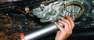
Gearbox repair and maintenance
When designing the tractor, the developers paid special attention to its maintainability in field conditions. All parts and assemblies had to be designed for repair in the field, when there is no access to qualified service personnel
Therefore, many drivers successfully carry out maintenance and repair of the T 40 gearbox with their own hands, minimizing costs and downtime.
Gearbox maintenance comes down to checking the amount of lubricant in the crankcase and periodically replacing it (or topping it up). You should check how much oil is in the T 40 box every 240 hours of operation using the control plug located on the box body. Oil is poured through the same hole when topping up or replacing - strictly to the level of the control mark, not lower and not higher.
A lack of lubrication will lead to increased wear and overheating of the gearbox, and an excess can lead to tooth breakage.
After every 960 hours of operation, it is recommended to wash the parts and components of the box and change the oil. The used oil is drained when the engine is hot through a hole in the lower part of the gearbox. Mineral gear oils are used, ideally all-season
In areas with significant changes in annual temperatures, it is important to ensure that the oil is seasonally appropriate.
Gears and gearbox shafts on the T 40 do not need adjustment.
Some tips for repairing and replacing main components:
- When replacing a bevel gear, both gears, driven and driven, are replaced. First, the leader is installed. The distance to the axis of the input shaft (40±0.1 mm) is adjusted by spacers under the bearing cup. The driven gear is installed with a gap in the teeth meshing of 0.25-0.6 mm. The bevel gear is installed in the same way.
- The gear locking mechanism does not require scheduled adjustment, but is subject to it after any disassembly.
If the differential lock does not operate properly, it is adjusted in the following order:
- unscrew the nut securing the adjustment bolt, while simultaneously screwing the bolt itself into the locking pedal from the bottom;
- fully depress the pedal;
- unscrew the bolt until it rests against the box lid;
- release the pedal, unscrew the bolt one more turn and secure with the nut.
Power steering repair
Troubleshooting power steering (power steering):
- Install the screw assembly with the front nut and front cover into the piston part so that the pin moves to the forward position.
- Turn the piston.
- Install a rod into the end hole of the nut.
- Using a screwdriver, turn the nut until it is completely secured with the bolt.
- Connect a pressure gauge to the steering column pressure line.
- Unscrew the plug.
- Place a stop between the bipod and the front side of the beam.
- Unscrew the cap and lock nut.
- Start the engine.
- Set the maximum number of crankshaft revolutions.
- While rotating the bipod, adjust the pressure level of oil fluid bypass through the safety valves.
- Tighten the locknut and cap.
- Replace the conical plug.
Selecting transmission oil
During long-term operation of a vehicle with a GAZ-3307 gearbox, the driver may encounter a problem such as oil leakage from the gearbox. In some cases, this may be due to the fact that the fastening bolts are loose, the oil seal has worn out, or there is a crack in the crankcase. Deformed parts must be replaced and new oil added.
Replacing transmission fuel is a type of gearbox repair. What kind of oil should be poured into a manual gearbox on a GAZ-3307? It is recommended to add TAP-15v transmission fluid to the gearbox; about 6 liters are required. The replacement frequency is 60,000 km.
Thus, the GAZ-3307 truck has good cross-country ability and is equipped with a reliable manual transmission, which is designed for a long service life. It should be periodically maintained and the transmission oil changed to reduce the risk of serious breakdowns in the automotive system.
GAZ trucks use a classic manual transmission, and the gearbox has undergone almost no changes over the past half century. The gear selection mechanism plays an important role in this gearbox - read the article about this transmission unit, its role, design, operation and repair.