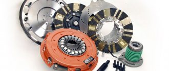
The clutch on a GAZ 53 truck is a problem area in terms of breakdowns; it often has to be repaired. There are a number of factors that cause various malfunctions:
- The machine is periodically loaded above the permissible limit and operated in difficult road conditions;
- The design of the clutch drive disc itself is far from perfect;
- The quality of the parts leaves much to be desired.
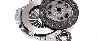
An example of an installed clutch on a GAZ 53 car
Parts and spare parts, maintenance, service and repair
GAZ cars
ZIL cars
KAMAZ vehicles
MAZ cars
KRAZ cars
URAL cars
- URAL-4320, 5557
- Engine YaMZ-236
- __________________
- MAP OF SITE
Technical adjustments of the clutch of the GAZ-53 car
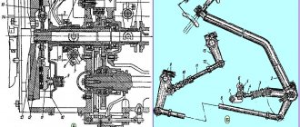
The clutch of the GAZ-53 car (Fig. 1) is single-disk, dry, with a damper device on the driven disk.
Installed in a cast aluminum crankcase 2. The clutch disc housing is attached to the crankshaft flywheel with six centering (special) bolts. A pressure disk (basket) is placed inside the casing.
Rotation of the GAZ-53 clutch basket is transmitted from the flywheel through three protrusions located in the disk and entering the casing windows. Torque from the engine to the gearbox is transmitted through the driven disk 3, clamped between the ends of the flywheel 1 and the pressure disk by the force of twelve springs 12.
Fig.1. GAZ-53 clutch and its drive
1 - flywheel; 2 - crankcase; 3 — driven disk; 4 — pressure disk; 5 — pressure plate lever; 6 — oiler; 7 — adjusting nut; 8 — clutch release; 9— gearbox drive shaft; 10—fork; 11 — casing; 12—pressure spring; 13 — adjusting nut; 14—thrust; 15— tension spring; 16 — clutch pedal
The clutch release levers 5 are located in the slots of the pressure plate protrusions and, using axles and needle bearings, are connected to the pressure plate and support forks, which are hinged on the casing by means of conical springs and spherical adjusting nuts 7. The nuts are centered after adjustment and the levers are not adjusted during operation. .
The GAZ-53 basket pressure disk is balanced as an assembly with the crankshaft and engine flywheel, therefore, when changing the driven disk during assembly, the “O” marks on the flywheel and the pressure disk housing are aligned.
The clutch control drive is mechanical. It consists of a clutch pedal 16, a roller with a lever, a rod 14, an adjusting nut 13. To lubricate the clutch pedal bushing, a grease nipple is installed at the end of the roller.
In the rearmost position, the pedal is held by a compression spring. In this case, the pedal travel in the rear position is limited by resting the pedal on the inclined floor of the cabin through a rubber protective coupling.
The clutch pedal 16 should have a free play of 35 - 45 mm or a free play of the outer end of the fork of 6 - 7 mm when the engine is not running, which corresponds to a gap of 4 mm between the ends of the pressure plate levers and the clutch release bearing.
The absence of this clearance leads to rapid wear of the levers, bearing failure and can lead to burning of the friction linings.
Adjustment and maintenance of the GAZ-53 clutch
Caring for the GAZ-53 clutch and its drive consists of periodically lubricating the clutch release clutch thrust bearing and adjusting the drive.
The clutch release bearing is lubricated using a grease cap 6 located on top of the clutch housing.
To do this, you need to squeeze the fully filled oil cap into it twice. Only the third fill of the oiler will supply lubricant to the bearing.
Adjustment of the GAZ-53 clutch release drive is required if the free play of the clutch pedal does not correspond to 35 - 45 mm.
The amount of clutch free play is adjusted by changing the length of rod 14. To increase the pedal free play, you need to unscrew the nut 13.
Premature wear of the linings, destruction of the linings and breakage of the driven disk hub along the windows under the springs can be caused, respectively, by driving with the clutch half-disengaged, engaging 2nd or 1st gear at high speed and unsmooth engagement of the clutch when switching to third or direct gear and can only occur if used incorrectly car.
Clutch repair for GAZ-53
The clutch is removed from the car without removing the engine. To do this, the car is placed on an overpass, lift or inspection hole to provide convenient access to the clutch from below.
Remove the gearbox along with the clutch and clutch release bearing. Disconnect the release spring from the coupling and press the bearing off the coupling. Unscrew the mounting bolts and remove the stamped lower part of the clutch housing.
Check the presence of aligned “O” marks on the engine flywheel and the pressure plate (basket) casing of the GAZ-53 and, if they are missing, apply them.
Gradually unscrew the bolts securing the clutch housing to the flywheel, while turning the engine crankshaft. Remove the driven and clutch pressure plates from the crankcase through the lower hatch.
Rice. 2. Position of the GAZ-53 driven and pressure disks at the time of their removal
1— flywheel; 2 — driven disk; 3—pressure disk (basket)
Since the second frame cross member prevents the simultaneous removal of the driven and pressure disks, they are removed sequentially.
Through the mounting hole for the gearbox, the clutch basket is lifted all the way into the crankcase, leaving at the bottom the largest possible gap between the flywheel and the clutch housing, through which the driven disk is removed (Fig. 2).
Then, by turning the pressure disk down one of the adjusting nuts, remove it, turning it so that the remaining adjusting nuts pass without touching the crossbar.
Dismantling the clutch pressure plate of the GAZ-53 basket. Before disassembly, make marks on the casing 11 (see, Fig. 1), levers 5 and pressure plate 4 in order to maintain balancing during assembly. Place the pressure disk on the stand and install it on the press table with a force of at least 30 kgf.
The casing should not touch the press table and stand. A lining is placed on top of the casing so that it does not cover the three nuts securing the support forks of the clutch release levers.
By pressing the press on the lining, the springs are compressed and the clutch release levers are relieved of the effort.
Unscrew the adjusting nuts 7 (see Fig. 1) of the support forks of the clutch release levers and smoothly release the press. Remove the clutch cover, pressure springs 12 and heat-insulating washers.
Undo the pins and remove the axles of the clutch release levers from the pressure plate ears. Remove the bearing needles: unpin and remove the axes of the clutch release levers from the support forks. Remove the bearing needles.
After disassembling, the clutch parts are thoroughly washed and carefully inspected, paying attention to the reliability of the rivet connections, the absence of bends, wear, cracks, nicks and breaks on the pressure and driven disks, levers, support forks, springs, hub, casing, clutch release fork and on other details of mechanisms.
The friction linings of the GAZ-53 driven disk are replaced if there are signs of overheating, cracks or heavy oiling on their surfaces, and also if the distance from the surface of the clutch linings to the rivet heads is less than 0.2 mm.
Replace both linings at the same time, since the difference in the thickness of the linings will disrupt the normal operation of the clutch. To remove worn or damaged linings, drill out and carefully knock out the rivets securing the linings to the leaf springs and disk with a punch.
Clutch repair
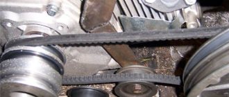
Hello dear friends! I haven’t written for a long time, and the reason why I haven’t written is simple, I didn’t know what to share with you. Today I met a friend. As he told me, not long ago he repaired the clutch on his lawn, that is, Gas 3307. But this is not so important; the clutch on both Gas 3307 and Gas 53 is the same. Only the clutch release drive on the Gas 3307 is hydraulic (see Fig. 1.), but on the Gas 53 it is mechanical (see Fig. 2.), I wrote this in case someone doesn’t know. But everything else is the same, as you and I know, the engine is the same, which basically means the clutch is the same.
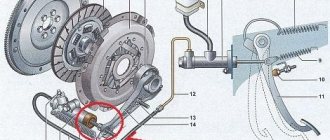
Drive clutch Gas 3307 hydraulic.
Fig.1. 1 - supply tank; 2 - supply hose; 3 - main cylinder; 4 protective cap; 5 — master cylinder pusher; 6 — clutch release; 7 - fork; 8 pedal; 9 — adjusting nut; 10 - lock nut; 11 — pusher; 12 — tension spring; 13 cylinder; 14 - piston; 15 — bleeding valve; 16 — piston of the main cylinder; 17 - cuff; A compensation hole; B - bypass hole.
Drive clutch Gas 53 mechanical.
Rice. 2. 1 — flywheel, 2 — crankcase, 3 — driven disk, 4 — pressure plate, 5 — pull-out lever, 6 — oiler, 7 — adjusting nut, 8 — clutch release clutch, 9 — gearbox drive shaft, 10 — fork , 11 — casing, 12 — pressure spring, 13 — adjusting nut, 14 — rod, 15 — release spring, 16 — clutch pedal.
As it turned out in a conversation with my friend, he cannot adjust the clutch after repair. First of all, I asked to list the entire list of work done from start to finish during the clutch repair. It turned out that both the flywheel and the drive disk did not need repair, that is, there was no wear on them. There was no need for grinding by the turner.
Clutch Gas 3307 and Gas 53.
Fig.3. A - 2.5-3 mm; 1 - flywheel; 2 - crankcase; 3 — driven disk; 4 — pressure disk; 5 — pressure plate lever; 6 — oiler; 7 — adjusting nut; 8 — clutch release clutch; 9 — gearbox input shaft; 10 - fork; 11 — casing; 12 — pressure spring.
In case anyone doesn’t know how the clutch-4 pressure plate and flywheel-1 (see Fig. 3.) are repaired. There's nothing to be afraid of; it's not that difficult. Place the pressure plate on the stand and place it on the press table. Place the lining on the casing so that it is convenient to unscrew the adjusting nuts-7. While pressing the lining with a press, unload the levers-5 from the force of the pressure springs-12, unscrew the adjusting nuts-7, smoothly release the press and remove the casing.
Clutch GAZ-53-12. Part 2.
Clutch of a GAZ-53-12 car
Part 2
Continuation. See the beginning of the article here: part 1
Dismantling and assembling the clutch pressure plate of a GAZ-53-12 car
Before disassembling, note the location of all parts relative to the pressure disk and the disk itself relative to the casing in order to maintain the factory balancing of the entire assembly after assembly.
Place the pressure plate on the stand and install it on the press table with a force of at least 300 daN (300 kgf) (Fig. 70). The casing should not touch the press table and stand. Place a lining (Fig. 71) on the casing so that it is convenient to unscrew the adjusting nuts. While pressing the lining with a press, relieve the levers and adjusting nuts from the force of the pressure springs, unscrew the adjusting nuts, smoothly release the press and remove the casing.
Undo the pins, carefully remove them and collect the needles of the thrust bearings.
Reassemble the pressure plate in the reverse order of disassembly. To maintain the factory balancing of the assembly, be sure to install all the parts in their places according to the marks previously made during disassembly.
- Thread the needles into the holes of the levers. To prevent the needles from falling apart during further work, secure them with rubber balls or rubber stoppers Ø 8 mm.
- Assemble the levers with the forks, install them on the pressure plate and secure the pins. When assembled with your fingers, the rubber balls of silt from the plug are pushed out.
- Install compression springs of the same group (same color).
- Install the casing on the press according to the previously made marks. Tighten the adjusting nuts and install the springs on the centering lugs of the casing.
- Adjust the clutch using a special tool or use a spare flywheel for this, placing three supports with a thickness of 12.2 mm ±0.02 mm under the pressure plate.
By tightening or unscrewing the adjusting nuts of the levers, ensure that the size from the surface of the flywheel to the end of the levers is 51.0 mm ±0.25 mm. (Fig. 72).
The difference between these dimensions of the day of one clutch should be no more than 0.3 mm. After adjustment, carefully (so as not to violate the established adjustment dimension) tighten the adjusting nuts by pressing the nut flange into the groove on the fork.
Replacing the friction linings of the driven disk
- Drill out the heads of the steel rivets securing the spring plates to the clutch disc and knock out the rivets with a punch.
- Drill and punch out the aluminum rivets securing the friction linings.
- Carefully, without allowing cracks to appear, rivet the new clutch disc lining and six spring plates to the other lining.
The end of all rivet heads for fastening the linings must be recessed at least 2.0 mm from the working surface.
The riveted head on the disk should be 0.6 mm + 0.3 mm high, and on the spring plates 0.9 mm + 0.3 mm, which will ensure that when assembling the driven disk, the riveted heads are buried in the holes of the spring plates to the disk.
Using steel rivets Ø 4×5 mm, rivet the plates to the disk and, if necessary, balance the driven river on the knives, ensuring, using balancing weights, a residual imbalance of no more than 18 g cm.
Before assembling the clutch, check the runout of the driven disk on the device (Fig. 73). Acceptable runout is up to 0.7 mm at a radius of 125 mm.
If the runout is greater than the specified value, the disc must be straightened.
Clutch GAZ-53 and GAZ-3307. How to install and adjust the clutch, read this article
Repair, installation and adjustment of the Gas-53 and Gas-3307 clutches
The clutch of the GAZ-53 car is dry, single-disk, equipped with a damper device on the driven disk and installed in a cast crankcase made of aluminum. The clutch basket is attached to the crankshaft flywheel using six centering bolts, inside of which there is a pressure plate. Rotation from the flywheel to the pressure plate is transmitted through three protrusions provided in the disk and included in the clutch basket windows.
From the engine to the gearbox, torque is transmitted using a driven disk, fixed between the ends of the pressure plate and the flywheel by the force of twelve springs. The clutch release levers are located in the slots of the pressure plate protrusions and are connected to the support forks and the pressure plate using needle bearings and axles. The support forks are hinged to the clutch housing using spherical adjusting nuts and conical springs. At the end of the adjustment, the nuts are tightened and the levers are not adjusted during operation.
The pressure plate is balanced as an assembly with the flywheel and crankshaft, so when replacing the driven disk, when assembling the clutch, it is necessary to align the “0” marks on the flywheel and the pressure plate basket.
The clutch of the GAZ-53 car has a mechanical control drive and consists of a clutch pedal, a rod, a shaft with a lever and an adjusting nut. To lubricate the clutch pedal bushing, a grease nipple is provided at the end of the pedal shaft.
The clutch pedal is held in its rearmost position using a tension spring. The pedal travel in the rear position is limited by resting the pedal on the cabin floor using a rubber coupling.
The clutch pedal free play should be 35-45 mm, and the pedal free play when the engine is not running should be 6-7 mm, which corresponds to a 4 mm gap between the clutch release bearing and the ends of the pressure plate levers.
In the absence of this gap, rapid wear of the levers, burning of the friction linings or bearing failure is possible.
Caring for the clutch and its drive involves periodically lubricating the clutch release clutch thrust bearing and adjusting the drive.
The clutch release bearing is lubricated using a grease cap located in the upper part of the clutch basket. Squeeze the fully charged oil cap into it twice.
Clutch disc and basket GAZ-53
The clutch on a GAZ 53 truck is a problem area in terms of breakdowns; it often has to be repaired. There are a number of factors that cause various malfunctions:
- The machine is periodically loaded above the permissible limit and operated in difficult road conditions;
- The design of the clutch drive disc itself is far from perfect;
- The quality of the parts leaves much to be desired.
An example of an installed clutch on a GAZ 53 car
Malfunctions
If the clutch stops working, you can understand this by the following signs:
- It is impossible to turn on any speed;
- The gear shifts into gear with a crunching and grinding sound;
- The pedal is pressed very lightly and falls through;
- The clutch pedal is not pressed to the end of its travel (not pressed to the floor);
- The pedal is located below the required level, closer to the floor in the cabin;
- Not every time you can turn on the speed normally - the clutch appears and then disappears;
- When changing gears, nothing happens and the car does not move;
- When starting off, there are jerks, the movement begins with trembling and beating;
- The gears turn on normally, the pedal pressure is also normal, but the car does not develop speed, there is no power;
- Whistle, noise when pressing the clutch pedal.
The cause could be any of the parts, but the signs are typical for breakdowns:
- The master cylinder is faulty - the pedal falls down, is pressed too easily, the clutch periodically disappears;
- The working cylinder is faulty - the pedal sticks and does not press all the way. If the cylinder is leaking and the liquid has left, it will be difficult to turn on any speed;
- The clutch basket feet are not adjusted - the car will start shaking and jerking. If the adjustment is severely disturbed, there may be a grinding noise when starting, and in some cases it will be impossible to start. The car may start shaking with “shaking” due to a bent clutch disc;
- The clutch feet are broken - most likely it will be impossible to move;
- The clutch disc is torn - the gears are engaged, but the car stands still and does not move;
- The clutch fork is broken - the pedal has dropped down, there is no normal release;
- The clutch disc linings were worn out - the car was slipping, not driving normally, the revs were roaring, but there was no power. The linings may also become oily, it is worth paying attention to oil leakage from the rear main bearing of the crankshaft - this is a disease on “lawns”;
- The release bearing is jammed or begins to make noise - the noise occurs when the pedal is pressed. A seized bearing leads to rapid wear of the clutch feet. Another sign is smoke and fumes in the area of the engine bell (clutch housing).
In general, there are many different options that can be named here, but the main ones have already been listed.
The GAZ-53 is equipped with a single-plate dry clutch with a damper device installed on the driven disk.
In recent years, petal baskets have appeared on sale for lawns; they are more convenient than foot baskets in that they do not require adjustment. But whether they are more reliable is another question. And claw baskets are better because they can always be repaired - repair kits for basket levers are available in every specialized store and are inexpensive.
Installed presser basket
Incomplete clutch engagement
If any of the gears is difficult to engage, and even with noise, then most likely there is an incomplete disengagement of the clutch, which can occur due to the large free play of the clutch fork.
In this case, you just need to adjust the free play. This may occur due to warping of the driven disk. It's better to replace it with a new one. You can also try to adjust the relative position of the ends of the clutch release levers, or clean the splines.
Replacing springs and linings
The GAZ-53 begins to accelerate more slowly than usual, does not pick up the required speed, and has difficulty climbing hills, this indicates that the clutch is not fully engaged.
This can happen if the compression springs no longer press with the required force, then they will need to be replaced.
Pay attention to the friction linings; they may be oily or worn out. If they are not very oily, then simply wash them with kerosene and rub them with fine sandpaper.
If there is heavy oiling, it is recommended to replace either the friction disc or the linings. The lack of free play of the clutch release fork also leads to such consequences. The clutch engages abruptly, this may be due to wear of the friction linings, which need to be replaced with or without the driven disk.
Other problems
The remaining symptoms and their treatment are the same as in the case of incomplete engagement of the clutch. If a squeaking sound occurs in the clutch, it is recommended to lubricate the clutch release bearing or replace it. You can also check the serviceability of the damper device.
Adjustment
If the claw clutch “twitches”, you can try to adjust it.
Adjusting the feet on a working car can be done in two ways, the first method is like a “book” method, the second is more often used in car repair shops.
- We put the car in the pit.
- Remove the clutch housing pan.
- Remove the clutch fork so you can get to the paws.
- We take a rod of wire (a little longer than a match) and use it as a measuring tool. While turning the flywheel, select the least loose foot and measure its height from the flywheel with a rod. The remaining two legs must be set to the same height. To adjust, turn the nuts in the desired direction; the nuts are located on the outside next to the paws.
- Having placed all the levers (paws) at the same distance, we check the operation of the clutch while driving. If everything is adjusted normally, do not forget to lock the adjusting nuts on the basket.
- Install the clutch housing pan. The work is done.
The first method does not always succeed in adjusting the clutch. The fact is that the paws run in needle bearings, and wear may occur in this connection. Then the second adjustment method will be somewhat more effective. The operations are still the same, but the essence of the adjustment itself is somewhat different.
It takes two people to do the work:
- We prepare a set of automotive feeler gauges for adjusting valves;
- We also remove the clutch housing pan;
- We fold several probes and dial approximately 1.5 mm;
- One of the participants presses and holds the clutch pedal, the second, between the disk and the flywheel, installs a feeler gauge under each foot;
- Under each paw, the probes should fit tightly, with the same force. Having established the gaps in this way, we check the work as it goes;
- And don't forget to tighten the adjusting nuts.
If the disc is not crooked and the paws are not too worn out, the second method helps to adjust the clutch normally the first time.
Clutch adjustment
So, before you start adjusting the clutch, in order to make sure that it is necessary, you need to make the following measurements:
- Using a tape measure or ruler, measure the full stroke of the pedal (normally 145-160 mm).
- Next, using the same method, we find out the amount of free play of the pedal (normal for a GAZ 53 clutch is 12–28 mm).
If the values deviate from the required norm, the pusher must be adjusted. This is done with narrow pliers; the pusher should be turned out or screwed into the eye until the required indicators are obtained.
Next, also with a tape measure or ruler, be sure to check the stroke of the working cylinder pusher at the moment the clutch is pressed. If the indicator is less than 14 mm, and the pedal travel is normal at the same time, simply remove air from the hydraulic drive. And when adjusting clutch parts, pay attention to the dust that accumulates on them. This is asbestos that is most harmful to health and must be removed from parts during vehicle maintenance. At the same time, blowing it off is strictly prohibited, because asbestos causes poisoning and even cancer if it enters the respiratory tract. The ideal option is to wash off the accumulated dust. In this case, you can only use special compounds, for example, methyl alcohol. Under no circumstances use water or gasoline for these purposes. This completes the basic clutch adjustment.
Replacing the clutch basket or disc
Having confirmed that the basket or disc is faulty, we change the clutch:
- We put the car in the pit;
- Removes the gearshift lever in the cabin;
- We unscrew the entire propeller shaft and move it to the side. We pre-install marks on the rear universal joint and on the rear axle flange. Installing the shaft in the same position will avoid vibration after assembly;
- Remove the release bearing fork;
- We turn away the handbrake rods from the gearbox;
- Unscrew the gearbox mounting nuts and dismantle it;
- Remove the clutch housing pan;
- Unscrew the six bolts securing the clutch basket. To unscrew everything, you will need to turn the engine flywheel.
Clutch of a GAZ-53 car
The flywheel is the outermost part mounted on the engine shaft. A “basket” is screwed to it with six tight-fitting bolts. The basket consists of a casing, a pressure plate and a driven disk. The driven disc is otherwise called the “GAZ-53 Clutch Disc”. If you do not touch the basket, the pressure plate presses with the elastic force of twelve springs on the driven circle, pressing it against the flywheel. Due to friction forces, the driven circle rotates together with the flywheel. The pressure circle receives torque due to three protrusions that are located in the windows of the clutch basket.
It should be noted that the basket rotates with the flywheel constantly, since it is rigidly connected to it. And the clutch disc periodically moves away from the flywheel and stops. This occurs when the driver presses the clutch pedal to change speed. The release spring 15 holds the pedal in the upper position. The driver presses the pedal, it goes down. Pushes a system of levers connected to rod 14. Through it, the force is transferred to the release fork. Which in turn drives the clutch release clutch.
To release the clutch, levers 5 are made, which are located in the windows of the protrusions of the pressure disk. The release clutch contains a bearing, which in turn presses on levers 5. They press the pressure circle away from the clutch disc, disconnecting the engine from the gearbox.
The flywheel, crankshaft and basket balance together. Place marks on the flywheel and on the casing. They must be combined during assembly.
When purchasing a clutch kit, you need to be well prepared, because the right choice will determine long-term performance and how easy it will be to press the clutch pedal.
Clutch adjustment GAZ-53
Its effective operation depends on the initial gaps between the clutch elements. When the engine is running, the pedal needs to move easily within 32-40 mm. When the engine is stopped, the optimal free movement is 6-7 mm. Such play will provide the required gap between the thrust bearing and the levers of the pressure circle.
If there are no these gaps, the bearing will constantly press on the levers and therefore will constantly rotate. Eventually it will fail. In addition, the friction linings of the clutch disc will burn. The specified gaps are adjusted by decreasing or increasing the length of the rod 14. To do this, you first need to loosen the nut 13. If you unscrew it, the rod will lengthen. If you turn it up, the thrust will decrease.
Timely lubrication of the rubbing parts of the clutch is very important. The most important part for lubrication is the clutch pressure bearing 8. It operates under difficult conditions: high speeds and high clamping force. To ensure high-quality lubrication, you need to squeeze the oiler 6 twice.
No adjustment will help if the driver changes gears incorrectly. This must be done by slowly releasing the clutch and sequentially switching gears. By accidentally jumping over speed, you can break the driven wheel hub. If the car is moving backwards, you cannot shift forward. Such an action will also lead to undesirable effects: breakage or premature failure of the friction parts.
Alignment dimensions for GAZ-53 clutch disc
Drivers and repair mechanics have great difficulty installing the clutch disc. Since this disk fidgets freely on the flywheel. If you install it by eye, then after installing the basket, often the drive shaft of the gearbox does not fit into the hole in the driven shaft.
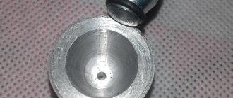
To facilitate this process, resourceful mechanics came up with a mandrel - centering.
The thick end with a diameter of 28.6 mm is inserted into the clutch disc. Thin with a diameter of 17 mm inside the flywheel. The minimum gap between the mandrel and the internal diameters of the mating parts ensures free sliding relative to each other. Therefore, you can press the driven circle against the flywheel. We obtain an ideal, coaxial mating of the flywheel and clutch circle. Then we put the basket on the flywheel.
There is a notch on the right side of the mandrel. This is done to make it easier to hold the alignment by hand. Diameter 24 mm free. That is, it can be made smaller, for example, 23 mm.
Clutch disc GAZ-53
If the clutch disc is worn down to the rivets, then the linings must be replaced. They change both at once, because they are installed with the same thickness. Chips and other visible defects are also not acceptable. To remove the covers, you need to remove the rivets. Usually they are drilled out.
Fresh linings are riveted so that the gap between the surface of the lining and the rivet cap is at least 2 mm. On both sides. After this operation, you need to measure the runout circle. Tolerance 0.7 mm at a distance of 130 mm from the axis of rotation.
After restoring the driven circle, it is mounted on the flywheel using the mandrel drawn above. But before that, grease or lithol is placed in the ball bearing, which is located in the flywheel.
Clutch master cylinder GAZ-53
Initially, the GAZ-53 car did not have a hydraulic clutch booster. Therefore, it was difficult for drivers to depress the clutch. Many craftsmen began to make alterations to the clutch. To increase pedal pressure on the clutch, hydraulic boost is applied through several levers. Its main components are the main and working cylinders, connected to each other by tubes. Without this reinforcement, it is possible to control the clutch, but it is difficult. When it does not squeeze out, the working cylinder is faulty. It is either leaking or there is no brake fluid in the system.
If the clutch master cylinder 53 is faulty, the pedal can be pressed easily. The clutch sometimes works, sometimes it doesn't. The first step is to check the presence of brake fluid in the system. It may disappear due to ruptured brake hoses.
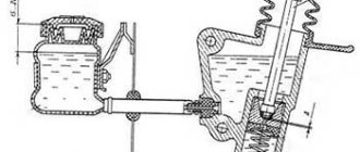
Before each departure, the driver must inspect the hydraulic clutch booster. It is necessary to control the amount of brake fluid in barrel 2. Outside there is a minimum volume mark. The level is made above this mark.
When the hydraulic booster is filled with brake agent, air enters it, which interferes with the normal operation of the mechanism. The pedal fails. Therefore, the system is pumped. Place the hose on the bleed valve 9, which is screwed into the GAZ-53 clutch slave cylinder - 8. The other end of the flexible tube is lowered into a vessel with brake fluid. The bleed valve is rotated counterclockwise half a turn.
Then press the clutch pedal. This creates pressure in the hydraulic drive system. The air is pushed through the hose into a bottle of brake fluid. When the pedal is at the bottom, resting on the floor, you need to screw the bleed valve into place. The pedal is released. The whole operation is done many times until air bubbles appear in the vessel (for this work it is advisable to take a transparent jar in order to better see the air floating from the flexible tube into the jar).
It is inconvenient for one person to undergo this operation. Since you will often have to go from the cabin to the bypass valve and back to the clutch pedal. Therefore, bleeding the clutch hydraulic drive is done by two people.
After completing this procedure, the free play of the pedal decreases. It should be between 32 - 38 mm. This distance allows for two gaps. The first, equal to 2.0 mm, is the gap between the pressure bearing 15 and the tips of the levers 14. If it is more or less than 2.0 mm, then it is changed by screwing or unscrewing the pusher 18 of the fork 17 from the tip 20. First you need to loosen the lock nut 19. Then it needs to be tightened.
The second gap is made 0.7 - 1.4 mm - the distance between rod 6 and piston 4 of the main cylinder. First, roughly, by eye, this gap is set using drive rod 7. Then precisely using asymmetrical bolt 5.
The movement of piston 21 should be 23 mm. If it is less, the clutch will not be fully depressed. This distance is not changed mechanically. If it is less than specified, then the hydraulic drive must be pumped.
Brake fluid is poured into the hydraulic booster. It strongly oxidizes the inner surface of the parts. Therefore, it must be changed every six months.
Adjusting the GAZ-53 clutch basket
When installing a repaired basket, it is important to line up the marks on the flywheel and the housing. If the pressure circle has become thinner after repair, then it is necessary to compensate for this decrease in thickness. To do this, metal washers are placed under the heat-insulating gaskets. Their height is equal to the decrease in the thickness of the circle. This allows you to maintain the pressing force of the springs.
The most important point when mounting the clutch basket is the accurate alignment of the heads of the clutch release levers. The uniform wear of the driven circle and, accordingly, the flywheel depends on this. Otherwise, the flywheel will suffer one-sided wear and lose its working geometry, which will lead to frequent clutch failures.
The extreme points of the tops of the levers should be in a plane parallel to the surface of the flywheel. For adjustment, use a spare flywheel. The basket with the pressure circle is placed on the surface of the flywheel. Three washers with a height of 10.2 mm are placed under the pressure circle. Bolt the basket to the flywheel. By turning the nuts on 24 clutch release levers, the gap between the tips and the working plane of the flywheel is 53 ± 0.75 mm.
Clutch on GAZ 53 - Clutch disc adjustment and alignment dimensions
The flywheel is the outermost part mounted on the engine shaft. A “basket” is screwed to it with six tight-fitting bolts. The basket consists of a casing, a pressure plate and a driven disk. The driven disc is otherwise called the “GAZ-53 Clutch Disc”. If you do not touch the basket, the pressure plate presses with the elastic force of twelve springs on the driven circle, pressing it against the flywheel. Due to friction forces, the driven circle rotates together with the flywheel. The pressure circle receives torque due to three protrusions that are located in the windows of the clutch basket.
It should be noted that the basket rotates with the flywheel constantly, since it is rigidly connected to it. And the clutch disc periodically moves away from the flywheel and stops. This occurs when the driver presses the clutch pedal to change speed. The release spring 15 holds the pedal in the upper position. The driver presses the pedal, it goes down. Pushes a system of levers connected to rod 14. Through it, the force is transferred to the release fork. Which in turn drives the clutch release clutch.