Adjusting the clutch basket KAMAZ 740
Adjusting the clutch of KamAZ 5320, 43118 and other models consists of adjusting the position of the clutch, pedal, booster pusher and basket. The need for the procedure is checked by measuring the distance from the bottom of the pedal to the floor surface - the distance should be no more than 16 centimeters.
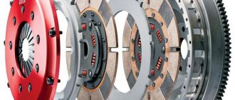
Design features of the clutch
Most KamAZ trucks use a double-disc clutch system (CC) with a radial position of power springs. To operate the mechanism, a special hydraulic drive equipped with a pneumatic amplifier is used. This scheme allows for a reduction in the effort required to depress the clutch pedal.
Clutch system diagram for KamAZ 4310 and 53215
Main elements of the device:
- Flywheel.
- Middle drive shaft.
- Driven pulley.
- Pressure disk.
- Crater device.
- Protective cover.
- Support fork.
- Gear shift lever.
- Deactivation clutch with bearing element.
- System shutdown plug.
- Thrust ring for shutdown levers.
- Release spring.
- A - play between the clutch bearing and the release lever ring.
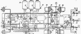
Connection diagram for the clutch drive KamAZ 43118 and 65115
Main components of the circuit:
- Clutch pedal.
- Main cylinder.
- Cylindrical element of a pneumatic booster device.
- Pneumatic booster follower mechanism for a device with two discs.
- Air duct.
- Working hydraulic cylinder.
- Shut-off clutch equipped with a bearing element.
- Shift lever.
- Stock.
- Pipelines and pipes of the hydraulic drive.
Driven disks in SS KamAZ 55111 or 43114 are manufactured using heat-resistant friction linings, which prevent rapid wear of structural elements. The device also includes a vibration damper that occurs when the engine cranks. The pedal of the drive unit is located on special bushings and usually functions without the need for regular lubrication. More modern versions of KamAZ 55102 and 6520 use Euro class single-plate clutches.
Clutches in KamAZ systems may differ from each other in the amount of transmitted torque.
The main feature of the improved versions of the SS is the presence of a built-in indicator that determines the wear of the friction linings. The gap is measured by the distance between the body of the amplification device, as well as the washer located on the rod. In case of serious wear, this figure may be about 2.3-2.5 cm. In some SS for KamAZ 43114 and 4308 with a PGU, it may not be possible to adjust the position of the rod.
Preparing for adjustment
Before properly adjusting and bleeding the clutch on Kamaz 740, 5511 or other trucks, you must perform the following steps:
- Check the tightness of the drive device. To do this, you need to depress the clutch pedal several times. The presence of a serious air leak can be determined by hearing, and a weaker one can be determined by using a soap solution. If brake fluid is leaving the system, this can be determined visually. If problems are detected in the tightness, the components are tightened or the pipes are replaced.
- Carry out diagnostics of the fluid level in the expansion tank of the drive device. The volume of consumables should be about 15-20 mm below the edge of the tank neck. If required, the fluid level is replenished. It is not recommended to mix supplies from different manufacturers when performing this task.
- Check the operation of the pedal release springs, as well as the system release fork pulley lever.
- Tighten the bolts that secure the pneumatic reinforcement device CC. This procedure is performed using a torque wrench. The tightening torque should be about 90-100 Nm.
- Drain condensate, if any, from the pneumatic hydraulic booster.
Adjusting the clutch operation
To complete the task, you will need a special homemade product in the form of a piece of wire, one side of which should be 2 mm and bent at an angle of 90 degrees. The thickness of the rod is at least 3-4 mm. This size is optimal for controlling the gap between the tab outline and the disc release component. Adjustment is made using the nut of the pneumatic booster device. The legs must be brought to the ring through a hole located in the upper part of the crankcase.
You need to adjust the clutch like this:
- The locking screws are unscrewed with a wrench.
- The stoppers and plates are dismantled.
- Each nut is loosened and released 5 turns; for convenience, it is recommended to use a ratchet. If the penny protrudes beyond the surface of the ring, it must be recessed, checking in advance for the presence of ferodo at the bottom.
- When performing this task, you can also change the spring elements if they are worn out. The paws should be positioned so that they are in equal contact with the ring.
- The disk area runout is checked. If necessary, the bearing device is lubricated. The adjustment gap should be about 29-30 mm.
Adjusting the clutch pedal free play
According to the official regulations, the stroke for moving the pedal should be about 6-12 mm, and the measurement itself should be done from the central component of the plate. The pedal must be released until the main cylinder starts working after pressing it. Adjustment is carried out using an eccentric pin; when making adjustments, the pedal must be pressed against the upper stop. The castle nut is tightened as much as possible and the full stroke is replaced, which should be 185-195 mm.
Source: https://starifaeton.ru/info/regulirovka-korziny-sceplenija-kamaz-740/
Two features of the KAMAZ clutch master cylinder
- A check valve is installed in all master cylinders, both clutch and brake. In order for the valve to close when pressed and create an axis of fluid pressure. When you release the pedal, the valve opens and allows the fluid to return back to the expansion tank. The role of the valve is performed by a membrane installed between the cuff and the piston. The piston has holes. Through which the fluid returns.
On the Kamaz clutch master cylinder, the role of the valve is played by the rod. There is a hole in the piston. When you press the pedal, the rod closes the hole. The rod at its base has a rubber sealing ring. Thanks to which the liquid is held under pressure. When releasing the pedal. The hole in the piston opens. The liquid from the PSU returns to the expansion tank.
- The clutch master cylinder is designed in such a way that it has an extension in its housing. This expansion is enough to provide enough fluid for the clutch to operate. Additionally, a plastic expansion tank is installed outside on the front panel of the cab. It is connected to the cavity of the clutch cylinder. And located on the same level with the extension of the cylinder. Therefore, liquid can be added both to this tank and directly into the cylinder cavity. After first removing the protective rubber casing of the rod.
Instructions for adjusting the clutch on KamAZ trucks
It is necessary to adjust the clutch on KamAZ 5320 and other models to maintain the good condition of the truck. Sometimes the need to carry out such work may arise on the road, so it is advisable for the car driver to know the basic conditions for independently and correctly setting up the mechanism.
Diagnostics, adjustment and pumping of KamAZ clutch
KamAZ PGU clutch drive
Adjustment of the KamAZ clutch may be required during the operation of the vehicle, since this unit is subject to serious loads. If the clutch “leads” or “slips”, if there is extraneous noise and crackling noise when shifting gears, it is necessary to carry out diagnostics and the necessary adjustments.
Diagnostics and adjustment of the KamAZ clutch includes the following actions:
- Visual inspection of the clutch drive.
- Adjusting the free play of the clutch pedal.
- Adjusting the free play of the release bearing clutch.
- Adjusting the full stroke of the clutch pneumatic hydraulic booster pusher.
- Bleeding the clutch hydraulic system.
Inspection and maintenance of the clutch drive
The clutch drive of Kamaz-5320 vehicles includes a clutch pedal with a release spring, a master cylinder, a working cylinder assembled with a pneumatic booster, pipelines and hoses for supplying working fluid from the master cylinder to the pneumatic booster, a compensation tank connected by a hose to the clutch master cylinder. Before any clutch adjustment, the drive should be inspected:
- Check the clutch drive for leaks. To do this, press the clutch pedal two or three times. A strong air leak is detected by ear, and a weak one is detected with a soap solution. Brake fluid leaks are checked visually. If a drive leak is detected, it is eliminated by tightening or replacing leaking elements.
- Check the fluid level in the clutch compensation reservoir. The fluid should be 15...20 mm below the edge of the reservoir neck. If necessary, add liquid to the required level. Mixing liquids of different brands is not allowed.
- Check the action of the release springs of the clutch pedal and the clutch fork shaft lever
- Tighten the bolts securing the pneumatic clutch drive booster. Tightening torque 90… 100 N*m (9…10 kgf*m)
- Drain condensate from the pneumatic hydraulic booster
If the clutch drive is mechanically in good condition, the necessary adjustments are made according to the set values.
Detailed instructions for adjusting the clutch on KamAZ trucks
Adjusting the clutch of KamAZ 5320, 43118 and other models consists of adjusting the position of the clutch, pedal, booster pusher and basket. The need for the procedure is checked by measuring the distance from the bottom of the pedal to the floor surface - the distance should be no more than 16 centimeters.
Most KamAZ trucks use a double-disc clutch system (CC) with a radial position of power springs. To operate the mechanism, a special hydraulic drive equipped with a pneumatic amplifier is used. This scheme allows for a reduction in the effort required to depress the clutch pedal.
Clutch system diagram for KamAZ 4310 and 53215
Main elements of the device:
- Flywheel.
- Middle drive shaft.
- Driven pulley.
- Pressure disk.
- Crater device.
- Protective cover.
- Support fork.
- Gear shift lever.
- Deactivation clutch with bearing element.
- System shutdown plug.
- Thrust ring for shutdown levers.
- Release spring.
- A - play between the clutch bearing and the release lever ring.
Connection diagram for the clutch drive KamAZ 43118 and 65115
Main components of the circuit:
- Clutch pedal.
- Main cylinder.
- Cylindrical element of a pneumatic booster device.
- Pneumatic booster follower mechanism for a device with two discs.
- Air duct.
- Working hydraulic cylinder.
- Shut-off clutch equipped with a bearing element.
- Shift lever.
- Stock.
- Pipelines and pipes of the hydraulic drive.
Driven disks in SS KamAZ 55111 or 43114 are manufactured using heat-resistant friction linings, which prevent rapid wear of structural elements. The device also includes a vibration damper that occurs when the engine cranks. The pedal of the drive unit is located on special bushings and usually functions without the need for regular lubrication. More modern versions of KamAZ 55102 and 6520 use Euro class single-plate clutches.
Clutches in KamAZ systems may differ from each other in the amount of transmitted torque.
The main feature of the improved versions of the SS is the presence of a built-in indicator that determines the wear of the friction linings. The gap is measured by the distance between the body of the amplification device, as well as the washer located on the rod. In case of serious wear, this figure may be about 2.3-2.5 cm. In some SS for KamAZ 43114 and 4308 with a PGU, it may not be possible to adjust the position of the rod.
about adjusting the clutch pedal
The “EIGHT ATMOSPHERES” channel in its video showed in detail how to increase the clutch pedal pressure on a KamAZ Euro.
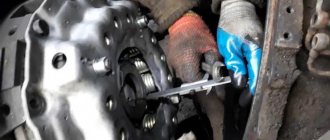
about adjusting the clutch basket without dismantling the gearbox
Taken by user Zheka Saltovsky.
When is clutch repair or replacement required?
Signs that may indicate a malfunction in the clutch system:
- sudden activation of the CC discs, which leads to a strong jerk during movement;
- difficulties when turning on speeds; switching modes may be accompanied by an uncharacteristic sound or crackling sound;
- weak dynamics and poor acceleration of the vehicle, the speed of the power unit does not correspond to the selected driving mode;
- the appearance of a burning smell while driving.
If one of these signs appears in the clutch operation, the user must stop driving and perform diagnostics and subsequent repairs. Using a vehicle with failed clutch discs can cause damage to the transmission unit.
: Clutch basket adjustment
The Auto and Moto channel in its video explained how the clutch of KamAZ 5320 and other models is adjusted.
Source: https://avtozam.com/kamaz/kak-otregulirovat-stseplenie/
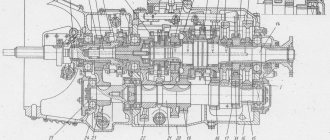
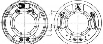
The leading parts of the clutch include the flywheel, the middle drive plate, and the pressure plate. The middle drive and pressure disks each have four studs on their outer surfaces, which fit into grooves on the cylindrical surface of the flywheel and transmit torque from the engine to the drive disks. At the same time, the possibility of axial movement of the disks is ensured.
The driven parts of the clutch include two driven discs. The driven disks are steel, equipped with friction linings made of asbestos composition, each connected to their hubs through a torsional vibration damper of the spring-friction type.
The hubs of the driven discs are mounted on the splines of the input shaft of the front gear divider. Pressure springs are installed between the casing and the pressure disk, under the action of which the driven disks are clamped between the pressure disk and the flywheel with a total force of 10,500...12,200 N (1050...1220 kgf).
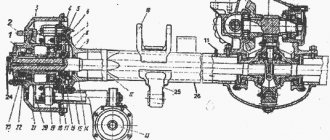
The clutch actuating device consists of release levers connected at the outer ends to the pressure plate, and in the middle part with support forks, which are installed in the casing, a thrust ring of the release levers and a release clutch with a bearing, mounted on the cylindrical part of the bearing cover of the front gear divider input shaft, and a shutdown fork mounted on the shaft.
When the clutch is engaged, torque is transmitted from the flywheel through the pin connection to the middle drive and pressure disks, then to the friction linings of the driven disks and through the torsional vibration dampers to their hubs, which are installed on the input shaft of the front gear divider. When the clutch is engaged, the thrust ring of the release levers moves away from the release clutch bearing 9 so that a gap A - - 3.2...4.0 mm is formed, ensuring complete engagement of the clutch.
Rice. 4.2. Clutch of KamAZ-5320 and KamAZ-4310 vehicles: 1 - makovik; 2 - middle drive disk; 3 — driven disk; 4 — pressure disk; 6 - crankcase; 6 - casing; 7 — support fork; 8 — shutdown lever; 9 — release clutch with bearing; 10 — shutdown fork; 11 — thrust ring of the shutdown levers; 12 — compression spring; A - gap between the thrust ring of the release levers and the release clutch bearing
When the clutch is disengaged, the release clutch with the bearing acts through a thrust ring on the inner ends of the release levers, which rotate on the needle bearings of the support forks. The outer ends of the release levers pull the pressure plate away from the rear driven disc.
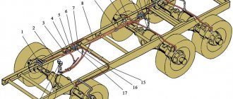
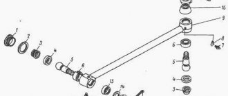
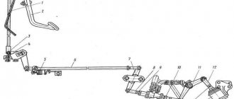
Rice. 4.3. Schematic diagram of the connection and placement of clutch control drive elements for KamAZ-5320 and K.AMAZ-4310 vehicles: a - schematic diagram of the connection of drive elements; 6 — placement and fastening of drive elements; 1 — clutch pedal; 2 - main cylinder; 3 — pneumatic booster cylinder; 4 — pneumatic booster tracking device; 5 - air duct; 6 — working hydraulic cylinder; 7 — release clutch with bearing; 8 — lever; 9 — rod; 10 - pipelines and hydraulic hoses
The middle drive disk, using an automatic lever mechanism mounted on the disk, self-aligns into the middle position between the ends of the pressure plate and the flywheel, freeing the front driven disk. Thus, between the driving and driven clutch disks, when it is completely turned off, there are gaps that ensure the separation of the driving and driven disks. driven parts and the “cleanliness” of the clutch disengagement.