Clutch of tractors MTZ-80, MTZ-82
The main clutch of the MTZ-80 and MTZ-82 tractors is a dry, single-disk, permanently closed clutch. Located in the dry housing compartment connecting the engine and gearbox
The driving parts of the clutch are the flywheel 1 (Fig. 1) of the engine 4, the pressure 11 and the support 10 disks.
The cast iron pressure plate has three lugs evenly spaced around its circumference that fit into the slots in the support plate.
Release levers 3 are attached to the ears.
Twelve pressure springs 9 are installed between the support and pressure disks.
On one side, the springs rest against the cups, which are installed in the support disk, and on the other, against the cast sockets of the pressure disk.
The driven disk 2 consists of a hub 12, a connecting disk 15 with friction linings attached to it, and a damper device 14.
Radial grooves (slots) are stamped into the connecting disk. This reduces its rigidity and improves the fit of the friction linings to the ground friction surfaces of the flywheel and pressure plate.
Friction linings are made of asbestos-based material and have ventilation grooves to improve heat dissipation and clean friction surfaces from wear products.
The linings are riveted on both sides to the connecting disk 15.
On the pressure plate side, six leaf springs are installed between the lining and the connecting disk. This design ensures smoother clutch engagement.
When the clutch is fully engaged, the leaf springs take a flat shape, and in the free state, the thickness of the driven disk is approximately 1-1.5 mm greater than when the clutch is engaged.
The driven disk is connected to the hub 12 by eight rubber dampers 14 installed in the sockets-grooves of the driven disk and the grooves of the limiting disks riveted to the hub.
Thus, the driven disk is connected to the hub mounted on the splines of the clutch shaft 13 not rigidly, but through a flexible device, which facilitates soft engagement of the clutch and reduces dynamic loads in the transmission.
Slowing down the rotation and stopping the shaft 13 and the associated input shaft of the gearbox, when the clutch is disengaged, is ensured by a brake.
Its drive disk with a riveted friction lining is secured to shaft 13 using a key and a locking ring.
The splined hub of the brake lift can move along the splines of the fixed lift arm.
The clutch shaft is braked when the brake discs are compressed.
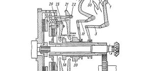
The release bearing can move along the lift bracket 5 when turning the fork 7 and the fork shaft 8. The fork shaft is rotated using lever 9 (Fig. 1, b), which is connected by a rod 8 to the pedal lever 2, and by a rod 11 to the brake activation lever 13 .
Pedal 1 is attached to lever 2.
When you press the pedal to disengage the clutch, the force is transmitted through rod 8 and lever 9 to the clutch release shaft and at the same time through rod 11 to brake lever 13.
The shutdown shaft with the fork 7 moves the tap 5 (see Fig. 1, a), which, through the levers 3, removes the pressure disk 11 and compresses the springs 9, releasing the driven disk 2.
When the pedal is released, the pressure plate, under the action of springs 9, returns to its original position, which leads to the engagement of the clutch.
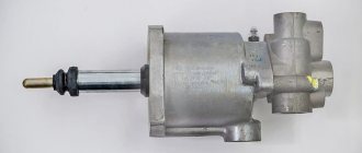
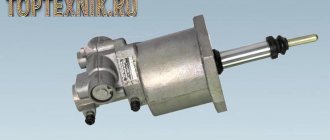
The clutch drive amplifier (servomechanism) serves to reduce the human muscular force applied to the controls.
The mechanical amplifier of the clutch drive of tractors of the MTZ family has a spring 3 (see Fig. 1, b), which is connected on one side to the fixed bracket 6 by means of an adjusting screw 4, and on the other side to a three-arm lever 2.
The lower arm of lever 2 is connected by rod 8 to lever 9 of the roller fork.
When the clutch is engaged, the geometric axis of spring 3 passes above the longitudinal axis of rotation of the three-arm lever 2 and the spring holds pedal 1 stationary.
As soon as force is applied to pedal 1 and three-arm lever 2 rotates around its axis, the axis of spring 3 will become lower than the axis of rotation of lever 2, and the spring will create a turning moment on the three-arm lever, which will make it easier to disengage the clutch and hold the pedal in the off position.
Clutch Maintenance
Clutch maintenance consists of periodic lubrication, checking and tightening of threaded connections and making adjustments,
During maintenance-1 (60 for old models, 125 operating hours for new models), you need to lubricate the release bearing with Litol-24 grease.
“Solidol S” or “Solidol Zh” through an oiler, which is located either on the clutch housing and connected by a flexible hose to the bearing, or on the outlet body.
During TO-2 (240 for old models and 500 operating hours per day for new models), the following work is performed to check and adjust the clutch.
In tractors MTZ-80 and MTZ-82, the free play of the pedals is checked - this is the main indicator of the correct adjustment of the clutch and brake.
The free play of the clutch pedal (see Fig. 1, b) should be 40 - 45 mm, which corresponds to a gap of 3 mm between the release bearing and the release levers.
The gap between the bearing and the head of each release lever should not differ from each other by more than 0.3 mm.
The clutch and brake control are interlocked; to adjust them, brake rod 11 is disconnected from lever 9.
Release the pedal from the influence of the servo spring, for which screw bolt 4 all the way into bracket 6 and loosen bolts 5 to allow movement of bracket 6.
By changing the length of rod 8, the free play of the pedal is set to 40 - 45 mm.
Place bracket 6 in its uppermost position, rotating it around axis 7 until it stops against bolt 5, and tighten the bracket fastening bolts.
By unscrewing bolt 4, return the pedal to its original position until it stops against the roller.
If the pedal is moved by the amount of free play, the spring should return it to its original position.
To adjust the brake, disconnect rod 11 from lever 13 and turn it counterclockwise until it stops.
In this position, the rod 11 is temporarily connected to the lever 13, and then the length of the rod is shortened by 7 mm. Reconnect the rod with the lever, pin the pin, and tighten the locknuts securely.
If the clutch has been disassembled, then the position of the release levers 3 (see Fig. 1, a) is disturbed.
Therefore, they must be adjusted using adjusting screws 4 so that the distance from the point of contact of the levers with the lift bearing to the end of the support disk hub is 12 ± 0.5 mm.
The difference in this size for individual levers should not exceed 0.3 mm. After adjustment, the screws are locked with locknuts.
Not available:
| № | Part code | Name | Part Information |
| Bearing-942/40-GOST-4060-60 | Bearing 942/40 GOST 4060-60 | Quantity per For all modifications 1 | Not available |
| 70-1601021-B | PTO drive shaft | Quantity per For all modifications 1 Unit weight, kg 2.9 Note Steel 45 Model 70 Group Clutch Subgroup Clutch Part serial number 021 Additionally Interchangeable with a part previously released under the same number | Not available |
| 70-1601076 | Ring | Quantity per For all modifications 1 Model 70 Group Clutch Subgroup Clutch Part number 076 | Not available |
| 70-1601081 | coupling | Quantity per For all modifications 1 Note Steel 25ХГТ Model 70 Group Clutch Subgroup Clutch Part serial number 081 | Not available |
| Ring-2V50-GOST-13940-68 | Ring 2B50 GOST 13940-68 | Quantity per For all modifications 1 | Not available |
| 70-1601086-B | PTO drive gear (II stage) | Quantity for all modifications 1 Unit weight, kg 3 Note Steel 25ХГТ Model 70 Group Clutch Subgroup Clutch Serial number of the part 086 Additionally Interchangeable with the part released earlier under the same number | Not available |
| 70-1601083 | Spacer washer | Quantity per For all modifications 1 Note Steel 08kp Model 70 Group Clutch Subgroup Clutch Part number 083 | Not available |
| Ring-2V90-GOST-13941-68 | Ring 2B90 GOST 13941-68 | Quantity per For all modifications 1 | Not available |
| 70-1601088-B | PTO drive gear (1st stage) | Quantity for all modifications 1 Unit weight, kg 3.36 Note Steel 25ХГТ Model 70 Group Clutch Subgroup Clutch Serial part number 088 Additionally Interchangeable with a part released earlier under the same number | Not available |
| 70-1601082 | Spacer washer | Quantity per For all modifications 1 Note Steel 65G Model 70 Group Clutch Subgroup Clutch Part serial number 082 | Not available |
| Ring-KSP-72-GOST-2893-73 | Ring KSP-72 GOST 2893-73 | Quantity per For all modifications 1 | Not available |
| 50-1601038 | Pressure washer | Quantity per For all modifications 1 Note Steel St.3 Model 50 Group Clutch Subgroup Clutch Part serial number 038 | Not available |
| 50-1601091 | Pad | Quantity per For all modifications 1 Note Paronite Model 50 Group Clutch Subgroup Clutch Part serial number 091 | Not available |
| 50-1601089 | Bearing cap | Quantity per For all modifications 1 Note Steel 10 Model 50 Group Clutch Subgroup Clutch Part number 089 | Not available |
| Bolt-M8-6gх16-88-35-019-GOST-7796-70 | Bolt М8-6gх16.88.35.019 GOST 7796-70 | Quantity per For all modifications 4 | Not available |
| 8T-OST-37-001-115-75 | Washer | Quantity per For all modifications 4 | Not available |
| Bolt-М12-6gх35-88-35-019-GOST-7796-70 | Bolt М12-6gх35.88.35.019 GOST 7796-70 | Quantity per For all modifications 1 | Not available |
| 12-OT | Washer OST 37.001.115-75 | Quantity per For all modifications 1 | Not available |
| Bearing-6-50306K-GOST-2693-73 | Bearing 6-50306K GOST 2693-73 | Quantity per For all modifications 1 | Not available |
| Bearing-943/30-GOST-4060-60 | Bearing 943/30 GOST 4060-60 | Quantity per For all modifications 2 | Not available |
| Bearing-210-GOST-8338-75 | Bearing 210 GOST 8338-75 | Quantity per For all modifications 2 | Not available |
| Bearing-305-GOST-8338-75 | Bearing 305 GOST 8338-75 | Quantity per For all modifications 2 | Not available |
| Bolt-М10-6gх30-88-35-019-GOST-7796-70 | Bolt М10-6gх30.88.35.019 GOST 7796-70 | Quantity per For all modifications 1 | Not available |
| Washer-10-OT-OST-37-001-115-75 | Washer 10 FROM OST 37.001.115-75 | Quantity per For all modifications 1 | Not available |
| Washer-10x6-01-019-GOST-6958-68 | Washer 10x6.01.019 GOST 6958-68 | Quantity per For all modifications 1 | Not available |
| Ring-025-030-30-1-4 | Ring 025-030-30-1-4 | Quantity per For all modifications 1 Note Rubber | Not available |
| 50-1601336 | Thrust bushing | Quantity per For all modifications 1 Note Steel 45 Model 50 Group Clutch Subgroup Clutch Part number 336 | Not available |
| 70-1601333 | Ring | Quantity per For all modifications 1 Note Steel 65G Model 70 Group Clutch Subgroup Clutch Part serial number 333 | Not available |
| Ring-2V62-GOST-12941-68 | Ring 2B62 GOST 12941-68 | Quantity per For all modifications 1 | Not available |
| 70-1601331 | Intermediate gear | Quantity for all modifications 1 Unit weight, kg 1.075 Note Steel 25ХГТ Model 70 Group Clutch Subgroup Clutch Serial part number 331 | Not available |
| 70-1601335 | Gear axis | Quantity per For all modifications 1 Note Steel 45 Model 70 Group Clutch Subgroup Clutch Part number 335 | Not available |
| Screw-М12-6gх25-58-35-019-GOST-1478-64 | Screw M12-6gx25.58.35.019 GOST 1478-64 | Quantity per For all modifications 1 | Not available |
How to extend the life of the ignition system
The driver should carefully monitor the condition of the mechanism when using the tractor. Timely diagnostics and maintenance will help prevent serious breakdowns and, as a result, unplanned repair costs. To keep your machine in working condition, you need to follow several important rules:
- every 60 operating hours, lubricate all parts of the unit;
- grease is considered the most suitable lubricant (when purchasing, pay attention to the presence of additional additives in the composition);
- check the free play of the pedal every 240 hours;
- keep an eye on the free play size. During operation, wear of parts leads to its gradual decrease. If the size is less than 30 mm, you need to install a new MTZ 80 clutch disc;
- Do not press the tractor clutch pedal for a long time. This way, system parts wear out faster;
- Do not jerk the clutch sharply. You need to move it smoothly and not leave it in an intermediate position for a long time;
- the clutch should not be left in the off state for a long time;
- check the linings every 120 hours. Their wear negatively affects the pedal speed.
Maintenance will keep the tractor in operation for a long time and reduce repair costs. In addition, buying new parts is always a financial investment. The machine operator himself can adjust the clutch on the tractor.
Device, spare parts and components.
SPARE PARTS FOR TRACTORS ADJUSTING MTZ TRACTORS ___________________
DIESEL ENGINE PARTS ___________________
MTZ SPARE PARTS CATALOG ___________________
TECHNICAL CHARACTERISTICS OF TRACTORS ___________________
SPECIAL EQUIPMENT BASED ON MTZ AND ATTACHMENTS ___________________
AGRICULTURAL MACHINERY AND EQUIPMENT ___________________
Repair of tractor clutch MTZ-80, MTZ-82
Slipping of the clutch or incomplete disengagement of gears leads to increased wear and breakdown of clutch parts, gearbox parts, rear axle and front drive axle of the MTZ-80, MTZ-82 tractor. The technical condition of the clutch can be determined by a number of signs that characterize a particular malfunction.
The appearance of abnormal noise and knocking, difficult gear shifting, clutch slipping, especially with increasing traction force, which cannot be eliminated by adjusting the clutch drive, indicate wear or destruction of clutch parts.
Increased noise or whistling when pressing the clutch pedal indicates destruction of the release thrust bearing. If the clutch drive of the MTZ-80, MTZ-82 tractors is incorrectly adjusted, which is characterized by the lack of clearance between the thrust bearing and the pressure levers, the bearing constantly rotates.
This leads to overheating of the bearing, leakage of lubricant and, ultimately, to destruction of the bearing. In most cases, jamming of a faulty bearing is accompanied by burning of the ends of the pressure levers.
Incorrect adjustment of the drive, weakening the force of the pressure plate springs can lead to clutch slipping, a decrease in tractor traction, and a decrease in the rotation speed of the power take-off shaft.
During operation of the MTZ-80, MTZ-82 tractor, the driven clutch discs warp, the linings wear out, and the rivet heads cause significant annular marks on the surface of the pressure plate. Due to increased local heating, tarnish and cracks may appear on the working surface of the pressure plate.
Clutch slipping may be a result of oil getting on the surfaces of the discs due to leaks through the seals of the diesel crankshaft or gearbox shafts.
If the driven disks are warped or the clutch release levers of the MTZ-80, MTZ-82 tractors are incorrectly adjusted (when the ends of the levers are located at different heights), it is difficult to engage the gears. In this case, the pressure plate becomes skewed when the clutch is released: the edges of the driven disk are pinched between the pressure disk and the flywheel. As a result, the clutch “leads”.
If the thickness of the driven disk is less than the permissible size, replace either the friction linings with new ones or the disk assembly. Difficulty shifting gears can be caused by jamming of the hub splines on the clutch shaft splines due to their stepwise wear.
When disassembling the clutch, simultaneously with eliminating the identified malfunction, a technical examination of the parts is carried out in order to replace them with new or repaired ones.
Before removing the MTZ-80, MTZ-82 clutch for repair, special technological bolts are screwed into the flywheel, providing preliminary compression of the pressure springs (Fig. 1), and the support disk mounting bolts are unscrewed, and then the technological bolts.
Before disassembling the clutch, bags are applied to the housing and pressure plates, trying to ensure the correct relative position of the parts during assembly and maintain the initial balancing of the clutch. The clutch is disassembled using a special tool.
Rice. 1. Removing the MTZ-80, MTZ-82 clutch for repair
1 — clutch; 2 - technological bolt; 3 — support disk mounting bolt
Permissible values of controlled parameters of clutch MTZ-80, MTZ-82, mm
Driven disk thickness - 8.0
Warping of the driven disk - 0.6
Pressure plate thickness - 21.0
Release lever cam height - 10.9
Definition of free play
Checking and adjusting the clutch on the MTZ-82 tractor should be done after 125 hours of machine operation in any conditions. To measure time, a special engine hour meter is used, located on the instrument panel in the cockpit.
Before starting work, you should measure the parameters of the free travel of the pedal to drive the clutch mechanism. Between the pedal and clutch levers there is a long rod mounted on the fingers. Under normal conditions, the clutch lever should follow the pedal movement by a distance of no more than 7 mm. This distance is measured along the radius of the finger. With such mobility of the lever, the free play of the pedal itself is from 40 to 50 mm.
