Instrument cluster KamAZ 69.3801. Pinout.
Instrument cluster KamAZ 69.3801. Pinout.
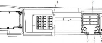
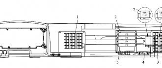
Rear panel of the KamAZ 69.3801 instrument cluster.
1 — password label; 2 - place for marking the serial number of the product; 3 — place of marking of the mark of conformity of the certification system (if there is a certificate); 4 — logo of the product manufacturer’s trademark; 5 — sticker; 6 — place of marking of the product designation; 7 — place of marking of technical specifications; 8 - place for marking the date of manufacture; 9 — connector “EZ”; 10 — sealing label; 11 — connector “E2”; 12 — connector “D”; 13 — connector “C”; 14 — connector “B”; 15 — connector “A”.
Connector “EZ” 953236-1.
| Contact | Contact assignment |
| 1 | Signal input for the “Transport position” indicator — “0 V” (signal — orange) |
| 2 | Signal input for the “Vehicle platform height adjustment” indicator is “0 V” (signal is red) |
| 3 | Free contact |
| 4 | Free contact |
| 5 | Free contact |
| 6 | Free contact |
| 7 | Signal input for the “ABS tractor” indicator is “0 V” (signal - orange) |
| 8 | Signal input for the "Trailer ABS" indicator - "0 V" (signal - orange) |
| 9 | Signal input for the "Engine fault" indicator - "0 V" (signal - orange) |
| 10 | Signal input 1 for the “Engine emergency” indicator - “0 V” (signal - red) |
| 11 | Signal input 2 for the “Engine emergency” indicator - “0 V” (signal - red) |
| 12 | Signal input for the "EFU" indicator - "0 V" (signal - orange) |
| 13 | Signal input for the indicator “Error in the exhaust gas aftertreatment system” - “0 V” (signal - red) |
| 14 | Free contact |
| 15 | Free contact |
| 16 | Free contact |
| 17 | Free contact |
| 18 | Free contact |
| 19 | Free contact |
| 20 | Free contact |
| 21 | Free contact |
| 22 | Free contact |
| 23 | Signal input for the “Traction control” indicator is “0 V” (signal - orange) |
| 24 | Free contact |
| 25 | Free contact |
| 26 | Free contact |
Connector “E2” 953118-4.
Possible malfunctions and ways to eliminate them
To ensure that no problems arise along the way, it is necessary to diagnose the system for faults before shipping.
Initially, when starting to work with this vehicle, if possible, it is necessary to carry out a quick diagnosis of systems and components. To do this, you need to light the dashboard without starting the engine. Among the indicators that light up, you need to find the lamps that are responsible for the technical condition of the battery and handbrake.
Kamaz 65115
It is also necessary to pay attention to the pressure values in the lubricant system and the glow plug fault sensor. After these simple manipulations, you can take two steps that are both easy and responsible.
- The next time you start the engine, the red indicators on the panel should go out. Only one red lamp should be on. It is responsible for the value of the handbrake. By tightening and releasing the handbrake, you can check the performance of this indicator.
- After a few seconds - from 15 to 20 - the engine can be turned off and the ignition, on the contrary, turned on. When the engine is running properly, the oil pressure indicator will not light up, which means that the pressure has risen to normal. If the engine is in good working condition, then the sensor will light up a couple of seconds after the engine is turned off. If the indicator flashes earlier or almost instantly, this is an alarming sign. Most likely, the motor is pretty worn out (the author of the video is Sergey Sergeich).
KamAZ 43118 - technical characteristics
KamAZ-43118 is an all-wheel drive truck with a 6 × 6 wheel arrangement. This vehicle, with its high cross-country ability, has become simply irreplaceable in hard-to-reach areas of Russia. Also, having a lifting capacity of 10 tons, the machine became the basis for a large number of various special equipment and, above all, truck cranes.
KamAZ-43118 has the following overall dimensions (in millimeters):
- Length – 8580;
- Width – 2500;
- Height – 3455;
- Ground clearance – 385;
- Wheelbase – 3960+1320.
The vehicle is equipped with a KamAZ-740.30-260 diesel engine that meets Euro-2 environmental standards. This power unit is made according to the V8 formula. It has a displacement of 10.85 liters, is equipped with a turbocharger and develops a power of 260 hp. With.
This power unit allows the car to reach a maximum speed of 90 km/h.
The empty weight of the truck is 10,400 kg. The weight of a fully loaded vehicle can be 20,700 kg.
History of appearance
Initially, the KAMAZ 5320 with a 6x4 wheel arrangement appeared in the production program of the Kama Automobile Plant, which became the platform for subsequent modifications:
- On its basis, KAMAZ 53215 appeared in 1979. Both models had a noticeable difference - the cabin was equipped with a berth;
- Since 2008, a number of components and assemblies have been installed on the KAMAZ 65117, although it is not a direct successor to the KamAZ 5320 model (see wiring diagram), however, the wiring diagram of the KAMAZ 65117 is in many ways similar to the 53215 model;
Power supply system for KamAZ-43118 vehicle
This system, perhaps, can be considered the main one in the car; thanks to this system, the truck is supplied with electricity when the power unit is running. The general diagram of the power supply system is presented below:
In the figure the numbers indicate:
- generator excitation winding cut-off relay;
- generator;
- fuse box;
- starter relay;
- starter;
- rechargeable batteries;
- mains switch;
- button for remote battery disconnect switch;
- heater motor relay;
- ammeter;
- fuses 13.3722 (7.5 A);
- fuse PR310 (10 A);
- instrument and starter switch;
I. to the EFU thermal relay
Brief explanations of the diagram:
The energy sources for this system are a generator (2) and two batteries connected in series (6). The negative terminal of the batteries, as in all cars, is connected to the housing. But, unlike passenger cars, on KamAZ it is connected through a special ground switch (7), which has a remote control.
Number 1 in the diagram shows a relay for disconnecting the generator excitation winding. This relay must break the circuit when the electric torch device (EFD), which is responsible for starting the engine in the cold season, is operating.
When the engine is running and the ignition is on (the ignition unit is indicated in the diagram as number 13), the circuit leading to the remote battery mass switch button (8) is opened. This is done so that the engine does not spontaneously turn off accidentally or as a result of a malfunction.
Let's look at the light signaling circuit next:
Truck crane: question - answer: PTO does not turn on.
For truck cranes with overhead PTO (on KamAZ chassis: “Galichanin”, “Motovilikha”, “Ulyanovets”).
If the power take-off (hereinafter PTO) does not turn on, proceed as follows: 1. Using the pressure gauge on the dashboard, check the air pressure in the pneumatic system. It must be at least 6 atm. 2. Loosen the tightening of the PTO activation pneumatic chamber pipeline (see figure) . With the engine off, turn on the pump - air should hiss from under the tube; turn off the pump - the hissing should stop. If you don’t hear a hiss of air when you turn on the pump, the electric pneumatic valve or its power circuit is faulty. And if hissing is observed, then the fault should be looked for in the PTO.
| Power take-off. Front view. |
3.First of all, check whether the position of the fork on the rod and the position of the PTO switch on the rear wall are adjusted correctly: maybe it is screwed in too deeply and does not allow the rod the required travel.
Further, the reason for non-engagement of the PTO could be either a jammed pneumatic chamber rod or a broken fork. To establish this accurately, you need to remove the top PTO cover and visually verify the integrity of the power fork. Next, using a mounting tool, press the fork with the clutch into the rearward position in the direction of travel. The rod with the fork and coupling should move quite easily, and when the impact is removed, return to its original position. If this is not the case, you will have to disassemble the PTO and find out why the rod is jamming. For truck cranes with side-mounted PTO. The checks are similar to those described above: 1. Check the air pressure in the pneumatic system - it should be at least 6 atmospheres. 2. Loosen the tightening of the PTO activation pneumatic chamber pipeline (see figure). With the engine off, turn on the pump - air should hiss from under the tube; turn off the pump - the hissing should stop.
If you don’t hear a hiss of air when you turn on the pump, the electric pneumatic valve or its power circuit is faulty. And if hissing is observed, then the fault should be looked for in the PTO.
avtokran-diagnostics.blogspot.com
External and internal lighting system KamAZ-43118
In addition to external lighting, this system is also responsible for lighting inside the vehicle’s cabin. It includes the following devices:
- headlights;
- fog lights;
- front lights;
- rear lights;
- engine compartment lamp;
- lamp for lighting the glove compartment and bed;
- instrument lighting lamp;
- cabin lighting lamp;
- portable lamp.
It has the following scheme:
- right fog lamp
- left fog lamp;
- right headlight
- glove box lamp;
- lamp switch;
- road train lights;
- road train light switch;
- heater motor relay;
- left cockpit light;
- right cockpit light;
- left headlight;
- fog light switch;
- brake signal relay;
- trailer solenoid valve switch;
- rear right lamp
- rear left lamp;
- front right lamp
- front left lamp;
- combination light switch;
- fuse 13.3722 (7.5 A);
- fuse PR 310 (10 A);
- instrument lighting switch;
- engine compartment lamp;
- hazard warning light switch;
- portable lamp socket;
- seven-pin socket;
- oil pressure indicator;
- fuel level indicator;
- speedometer;
- tachometer;
- coolant temperature gauge;
- ammeter;
- pressure gauge;
I. to the instrument and starter switch
All devices, except for the glove compartment light, are connected using a single-wire circuit. As for the glove box lighting lamp, its negative contact is connected to the fuse block.
As for the low and high beams (numbers 3,11), dimensions, fog lights (1,2), they are turned on and off by a combination switch (19) connected through an ammeter.
To protect low beam headlights, as well as fog lights, from short circuits, they are powered through PR310 thermobimetallic fuses. High beams have their own fuses.
The size circuits and instrument lighting lamps are also protected from short circuits by thermobimetallic fuses of type 13.3722.
Features of the driver's seat
In comparison with other trucks, the KAMAZ generation immediately became the standard for an organized driver’s seat:
- Thanks to the new comfortable cabin;
- Modern governing bodies;
- Improved lighting devices that meet the requirements for freight transport operating in off-road city conditions;
- An efficient heating system for the cabin in general and the driver's seat in particular.
For reference: That is why the automaker used the same cabin concept on all modifications without exception, including flatbed, tilt and body versions of the cargo platform with a 6x4 wheel arrangement. Thanks to this, the selling price of the car remained the same.
Instrumentation system
As you might guess from the name, this system is designed to service various instrumentation, indicators and sensors. Instruments are located on the dashboard of the car, and sensors are located in its various components and mechanisms.
The electrical diagram of this system is as follows:
The numbers on the diagram indicate:
- fuel level indicator;
- fuel level sensor;
- fuse 13.3722 (7.5 A);
- coolant temperature indicator sensor;
- coolant overheat sensor;
- emergency oil pressure sensor;
- oil pressure indicator sensor;
- oil pressure indicator;
- 11 — blocks of warning lamps;
- coolant temperature gauge;
- generator;
- tachometer;
- speedometer;
- speedometer sensor;
I. to the instrument and starter switch
Description and location of indicators and instruments on the panel
In the driver's cabin you can find many incomprehensible devices, the purpose of which must be explained for the correct operation of the vehicle. Each of these devices is located on a special panel, which folds back and is located on the left side of the panel.
The first device where the eye falls is the steering wheel. It is located in the picture below at number 6 and makes it convenient to monitor the readings that are displayed on the measuring instruments in the cockpit. Thanks to the figure below, you can find out the purpose of each button, pedal and lever that are located in the driver’s cab.
Purpose of instruments in the driver's cabin
- Auxiliary (direct) brake control button.
- The pedal is responsible for the clutch.
- A pedal responsible for controlling the brake valve.
- A pedal that controls the start of fuel.
- Air pressure distributor.
- Steering wheel.
- Windshield cleaning device.
- Window lift system lever.
- Gearbox control knob.
- Handle for closing the door.
- Handle for longitudinal movement of the passenger seat.
- Lever for adjusting the backrest of the passenger seat.
- Driver's seat suspension stiffness control lever.
- Engine cable.
- Valve handle for parking and emergency brakes.
- A device that fixes the adjustment of the backrest angle of the driver's seat.
- Fuel supply thanks to manual control.
- The handle responsible for the function of longitudinal movement of the driver's seat.
- Cabin fairing.
Instrument cluster
Below is how to diagnose problems in advance, as well as the most common breakdowns, including those due to improper use of the cigarette lighter.
KAMAZ blue
Device
The speedometer on KamAZ is a device for measuring the speed of a vehicle. The device connects to a speed sensor and a topographer.
- Pointer - speed is shown by moving the arrow across the dial.
- Tape - the location of the tape on the horizontal scale shows the speed.
- Drum - the indicator is placed on a drum that rotates in proportion to the change in speed.
A mechanical dial meter is installed on many machines.
Analog meter device:
- Worm unit, which is installed in the gearbox.
- A gear that rotates together with the gearbox shaft. This makes it possible to calculate the rotation speed of the drive and wheels.
- The wire that runs from the worm assembly to the instrument panel.
- Magnetic element.
- A metal plate attached to the arrow.
- Scale.
- Spring.
An accompanying element of the device is a counter, which determines the length of the path traveled and is connected to the cable via a worm gear.
In the electronic device, there is no mechanical connection between the data on the instrument panel and the transmission output shaft. The device is:
- Optoelectronic, in which there is a high-speed part with a cable, and the speed data is determined by photointerrupter pulses.
- Bestrosov, in which a magnet is installed, rotating in place with the gearbox shaft. Changes in the magnetic field are converted into pulses by the bridge circuit.
A popular meter that operates using the Hall effect. Changes in output voltage are proportional to the rotation speed of the disk. The frequency of the voltage pulses allows you to determine the speed of the machine.
Speedometers
Speedometer 87.3802010 or PA 8046-4P
Speedometer 81.3802010
Diameter 140mm, runs on 24 volt on-board network. It is mainly used on Kamaz or Maz trucks. There is a total and daily mileage counter and a speed limit alarm.
Speedometer 811.3802010
Diameter 140mm, runs on 12 volt on-board network. Suitable for GAZ, KAZ and PAZ.
Speedometer 85.3802010
Diameter 100mm, runs on 12 volt on-board network. Suitable for GAZ, UAZ and ZIL. Daily and total mileage counter. Very compact with a depth of only 7 centimeters.
You can buy these components from almost any supplier or at Avtopribor” in Vladimir.
tell me which sensor is suitable for the tachograph siemens vdo car maz 1999.
