Hydraulic distributors (hydraulic distributors) are devices designed to control the flow of working fluid in a system using external influence (signal). During the operation of a hydraulic system, it often becomes necessary to change the direction of flow or the force of flow. For this purpose, various designs of hydraulic distributors are used. As a rule, hydraulic valves are made by casting from high-quality steel, modified cast iron or bronze. Type of connection to the main hydraulic system - threaded, flanged or butt.
Types of hydraulic valves
Depending on the type of shut-off and control element, valve and spool valves are distinguished.
- Spool Direct acting Manual control
- Mechanical control
- Electrical control
- Hydraulic control
- Pneumatic control
- Electrohydraulic control
- Direct action Manual control
- Electrohydraulic control
Spool valves
Valve distributors provide better tightness; they are able to operate at higher pressures than spool valves.
Distributors with a spool valve are more compact; they allow smooth closing of the working windows, which is important in the presence of large inertial masses.
Let's take a closer look at the design, characteristics and operating principle of spool valves, which are widely used.
Number of hydraulic valve positions
The number of options for connecting hydraulic lines with a distributor is called the position number. The most widespread are two- and three-position valves.
Neutral is the position in which the spool is installed in an inactive state under the influence of simultaneously acting forces (for example, spring force).
Number of supplied lines
Distributors can vary in the number of lines supplied, the most commonly used are four-line hydraulic distributors, 4 lines are supplied to them:
- p—pressure
- t - drain
- a - output a (for example, supplying fluid to the piston cavity of a hydraulic cylinder)
- b - output b (for example, supply of working fluid to the rod cavity of a hydraulic cylinder)
Classification of hydraulic engineering
These devices are divided based on the typology of locking structures. Hydraulic distributors, the types of devices of which differ in functionality, are divided into the following types:
- spools;
- tap distributors;
- with valve;
- jet;
- with a regulating element of the “nozzle-flap” type.
Spool valve types are very common. They are simple to manufacture, compact and reliable in operation. They can withstand increased pressure up to 32 MPa and active flow, unlike the crane type.
The tap distributor is also quite widespread. Its valve design is based on the cylindrical shape of the rotary valve plug. But the tap can also have a spherical, conical shape, and can also be flat. The variety of types of locking elements makes this type of device very convenient and in demand.
Valve-based devices make it possible to avoid leakage of the working medium, which is often found in the case of spool valves. When the pressure exceeds 32 MPa, it is difficult to keep the hydraulic motor itself in a stationary position; positional switching is required here. In this case, a valve distributor is relevant, which has an increased weight and size and completely seals the entire hydraulic line. This type of distributor is relevant where high tightness is required. The locking structure is usually made in the form of a cone or ball valve.
The “nozzle-flap” type of device operates on the principles of a hydraulic pressure divider and qualitatively distributes the load during the flow of the working medium.
Inkjet options are characterized by reduced sensitivity to contamination; this is ensured by the complete absence of moving elements in the device.
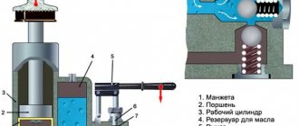
Design and principle of operation of the hydraulic distributor
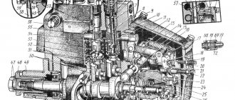
Let's consider the design of a four-line three-position distributor locked in the neutral position.
The operating principle of the hydraulic distributor circuit 44 is demonstrated in the video.
The distributor body has channels for supplying liquid. The spool is installed in a hole bored in the body.
The distributor spool is a part, usually cylindrical, on which are made belts, grooves, grooves necessary for separating or connecting various channels made in the distributor body.
In the neutral position, the spool is held by springs, at which point it closes line P. If there is a control signal, electromagnet 1 will move the spool to the right. In this position, the spool will connect channels p and a, t and b. In the absence of a control signal, the springs will return the spool to the neutral position. If there is an electrical signal at electromagnet 2, the spool will move to the left, connecting channels p and b, t and a.
Spool valves
Spool valves are cylinder-shaped rollers that are carefully processed. There are provided machined sockets in specific locations. They are placed in suitable and prepared places in the body. During installation, the spools pass through special channels and cavities towards the axes. As a result, the spool elements slightly open some channels, closing other working holes. This design helps change the direction of fluid flow. The spools are driven by a lever that operates in four positions:
- Neutral position.
- Work on the rise.
- Free swimming.
- Forced lowering.
The indicated positions of the P-80 hydraulic distributor have a certain fixation. Holding the lever by hand is only possible in the “forced lowering” position. The spool devices are equipped with an automatic return system to the neutral position from fixed modes.
Designations of hydraulic distributors
In the designation of the distributor, the number of main lines supplied to the distributor and the position are indicated through the fraction. For example, a four-line three-position valve will be designated 4/3. The distributor designation also indicates the circuit number (see table below).
Hydraulic diagram of the distributor
In a hydraulic diagram, a hydraulic distributor is indicated by a series of rectangles, each of which represents a different position of the distributor.
In each rectangle, lines show which channels the distributor will connect in a given position.
To learn more about how to read hydraulic diagrams with a distributor, see the article on how to read hydraulic diagrams.
According to GOST 24679-81, the following hydraulic distributor circuits .
Distributors 64, 44, 574, 34 schemes are among the most common. Distributor 64 of the circuit in the neutral position allows you to unload the pumping station by sending the working fluid to drain.
Basic versions of distributors according to hydraulic circuit
Using the data presented in the table, we can conclude that the distributor circuits correspond to:
- Distributors Atos 0710, Duplomatic S2, Parker 2C, Caproni 00, Rexrot H correspond to scheme 14 according to the Russian classification
- The 24 diagram corresponds to valves Atos 0718, Duplomatic S10, Parker 6C, Caproni 05, Rexrot M
- 34 scheme corresponds to valves Atos 0713, Duplomatic S3, Parker 4C, Caproni 04, Rexroth J
- 44 scheme corresponds to valves Atos 0711, Duplomatic S1, Parker 1C, Caproni 01, Rexroth EB
- 64 diagrams correspond to distributors, Atos 0714, Duplomatic S4, Parker 9C, Caproni 02, Rexroth G, etc.
- The 574 scheme corresponds to valves Atos 0630/2, Duplomatic TA002, Parker 30B, Caproni 11, Rexroth C
Operating principle
Hydraulic distributors are made of high quality steel, modified cast iron or bronze. Some elements are treated for additional protection: they are nitrided, cemented, etc. Size and weight depend on the volume of working fluid. The more it passes through the system, the more impressive the dimensions and weight are usually.
Let's consider an elementary diagram of the operation of a hydraulic distributor. In the initial state, liquid from the pump does not flow into the hydraulic cylinder. As soon as the operator moves the shut-off and control mechanism in one direction, it begins to flow into the corresponding cavity of the cylinder, causing the piston to start moving. The liquid that the piston begins to displace goes down into the tank. After completing the task, the operator returns the mechanism to its initial position.
The devices can be guiding or throttling. In the first case, the distributor only opens or closes the fluid passages. Throttling models provide the ability to regulate the flow rate. This occurs due to the ability of the locking and regulating mechanism to open the channel not only entirely, but also partially. The advantage of such designs is the absence of sharp shocks when turning the mechanism on/off.
Help in selecting equipment
Your message has been successfully sent!
How to select parameters
The hydraulic separator is selected taking into account the maximum possible coolant flow rate. The fact is that at high speeds of liquid movement through the pipes, it begins to make noise. To avoid this effect, the maximum speed is assumed to be 0.2 m/s.
Parameters required for the hydraulic separator
By maximum coolant flow
To calculate the diameter of the hydraulic arrow using this method, the only thing you need to know is the maximum coolant flow that is possible in the system and the diameter of the pipes. With pipes everything is simple - you know which pipe you will use for wiring. We know the maximum flow that the boiler can provide (it is in the technical specifications), and the flow rate through the circuits depends on their size/volume and is determined when selecting circuit pumps. The flow rate for all circuits is added up and compared with the power of the boiler pump. A large value is substituted into the formula to calculate the volume of the hydraulic needle.
Formula for calculating the diameter of a hydraulic separator for a heating system depending on the maximum coolant flow
Let's give an example. Let the maximum flow rate in the system be 7.6 cubic meters/hour. The permissible maximum speed is taken as standard - 0.2 m/s, the diameter of the pipes is 6.3 cm (2.5 inch pipes). In this case we get: 18.9 * √ 7.6/0.2 = 18.9 * √38 = 18.9 * 6.16 = 116.424 mm. If we round, we find that the diameter of the hydraulic needle should be 116 mm.
According to the maximum boiler power
The second method is to select a hydraulic needle according to the boiler power. The estimate will be approximate, but it can be trusted. The boiler power and the difference in coolant temperatures in the supply and return pipelines will be needed.
Calculation of hydraulic arrow according to boiler power
The calculation is also simple. Let the maximum boiler power be 50 kW, the temperature delta be 10°C, the diameters of the pipes be the same - 6.3 cm. Substituting the numbers, we get - 18.9 * √ 50 / 0.2 * 10 = 18.9 * √ 25 = 18.9*5 = 94.5 mm. Rounding, we get the diameter of the hydraulic needle 95 mm.
How to find the length of the hydraulic arrow
We have decided on the diameter of the hydraulic separator for heating, but we also need to know the length. It is selected depending on the diameter of the connected pipes. There are two types of hydraulic arrows for heating - with taps located one opposite the other and with alternating pipes (located offset from one another).
Determining the length of the hydraulic arrow from a round pipe
It is easy to calculate the length in this case - in the first case it is 12d, in the second - 13d. For medium-sized systems, you can select the diameter depending on the pipes - 3*d. As you can see, nothing complicated. You can calculate it yourself.
Varieties
Depending on the type of main element, you can buy the following hydraulic valves:
- spool type;
- valve type;
- crane type.
Spool valves
The main element of such distributors is a cylindrical or flat spool. In the simplest scheme, everything happens as we described above. In the “quiet” position, the spool closes the channels. When it moves to the left, the liquid rises into the left cavity of the cylinder, as a result of which the piston moves to the right. If the mechanism is moved to the right, the liquid will begin to fill this side of the hydraulic cylinder, forcing the rod to retract back. The process of returning the piston to its original position is usually faster, since the filling area is smaller.
Based on the number of fluid flow lines, two-, three-, and multi-port hydraulic valves are distinguished. The system control can be manual or hydraulic, electromagnetic or electrohydraulic. When using only muscle power, a button, lever, rotary handle or foot pedal is used. In the case of a mechanical device, the process is started by a pusher, roller or spring. Pressure can be direct hydraulic or pneumatic.
Often the system uses several spools at once. Such designs are divided into monoblock and sectional. If there are several compartments, they are connected with bolts. The shut-off and control mechanism for this type of distributor is available in three versions: with positive, zero and negative axial overlap. Each of them has its own advantages and disadvantages.
The advantage of the first option is the ability to fix the position of the piston. Minus: there is a dead zone within which the actuator does not move even in the presence of a signal. Spools with zero axial coverage do not have such an area. Their disadvantage is the relatively high cost associated with difficulties in manufacturing. Models with negative overlap have a minimal dead zone. The negative factor here is the less rigidity of the structure.
Crane
These hydraulic valves regulate flows by turning the valve plug. The most popular products are cylindrical and conical in shape. Flat and spherical models are also available. One of the most important characteristics of such devices is tightness. Over time, the gap between the plug and the valve body may increase, resulting in leakage of the working fluid.
Users of hydraulic valves with a cylindrical plug most often encounter this problem. Initially, the gap between the surfaces is 0.01...0.02 mm. As the structure wears out, the plug and the body begin to fit together less tightly. You have to either put up with constant fluid losses (after all, they are not too great), or buy a new device. Models with a conical plug do not have this problem, which makes their purchase more profitable.
Valve
Hydraulic distributors, which use a valve as a shut-off and control element, are capable of operating at high pressure. If spool designs are limited to a nominal value of 32 MPa, then valve designs can withstand loads two to three times greater. The flow vector of the working fluid is regulated by sequential opening/closing of the passage channels.
When the motor needs to be activated, the operator moves the rod on which the protrusions are located. As a result of this movement, one of the pairs of valves opens, and the liquid begins to move through the corresponding channel. It either enters the hydraulic motor or is drained into the tank. At the end of the process, the rod returns to its original position.
Valves for distributors can have a variety of shapes, ranging from balls to cones. They are controlled manually, mechanically or electrically. Of the devices driven by muscular efforts, the most widespread are elements with a swinging lever. In many designs, the valves are opened/closed using a cam drive.
The ability of these hydraulic valves to withstand severe pressure affects the dimensions and weight of the products. They are significantly heavier and larger compared to spool-type models that pass the same amount of working fluid. You should also take into account the sharp fit of the valves on the seat. From time to time, serious water hammer may occur, which negatively affects the operation of the entire system and its service life. In view of this, such devices are not recommended for use in structures where high inertia of moving masses is allowed.
Schemes for self-manufacturing hydraulic arrows
When assembling a hydraulic arrow with your own hands, the main thing is to make the calculations correctly and have the skills to work with a welding machine.
First of all, it is necessary to find the optimal dimensions of the hydraulic separator:
- internal diameter: divide the sum of all heating boiler capacities in kW by the temperature difference between the supply and return, take the square root of the resulting parameter, and then multiply the last value by 49;
- height: multiply the inner diameter by six.
- spacing between pipes: multiply the internal diameter by two.
Based on the obtained parameters, you need to draw up a drawing or use one of the diagrams of the future hydraulic distributor presented by the Plumber Portal resource. After this, you need to prepare a steel tube of round or square cross-section, which corresponds to the calculated indicators, and weld the required number of pipes with threaded connections into it.
Despite the simplicity of the device, the characteristics of the hydraulic gun must still correspond to specific conditions. Also, when assembling it yourself, you need to understand what to start from.
The classic assembly of a typical hydraulic boom is based on the “three diameter rule”. That is, the diameter of the pipes is three times smaller than the diameter of the main cylinder of the separator. The pipes are diametrically opposite, and their height arrangement is also tied to the main diameter.
Classic hydraulic separator diagram:
Some change in the position of the pipes is also used - a kind of “ladder”. This modification is aimed mainly at more efficient removal of gas and insoluble suspended matter. When circulating through the supply pipe, a slight change in the direction of the liquid flow in a zigzag downward manner contributes to the best elimination of gas bubbles.
On the reverse flow, on the contrary, the step is upward, and this simplifies the removal of solid sediment. In addition, this placement promotes optimal mixing of flows. The proportions are chosen to create vertical flow conditions in the range of 0.1 to 0.2 meters per second.
Exceeding this limit is prohibited. The lower the speed of the vertical flow, the more effective the separation of air and sludge will be. The slower the movement, the better the mixing of flows with different temperatures. As a result, a temperature gradient is formed along the height of the device.
Diagram of a hydraulic arrow with a stepped arrangement of pipes:
If the heating system contains circuits with different temperature conditions, then it is worth using a hydraulic distributor that acts as a collector, and different pairs of pipes will have their own temperature pressure. This will significantly reduce the load on thermostatic devices, making the entire system more manageable, efficient and economical.
The closer the pair of pipes is to the middle, the lower the temperature pressure in the supply tube, and the smaller the temperature difference in the supply and return. For example, for batteries the best mode is 75 degrees in supply with a difference Δt = 20 ºС, and for a heated floor system 40÷45 with Δt = 5 ºС is enough.
Diagram of a hydraulic separator with three outputs to the heating circuits:
Horizontal placement. In such variations, of course, there is no question of removing sediment and air. The placement of fittings varies significantly - to effectively move liquid, circuits are often used even in the opposite direction of the flow of the “small” and heating circuits.
Such a hydraulic arrow is made in order, for example, to place equipment more compactly in a boiler room, since the counter direction of flows makes it possible to slightly reduce the diameter of the tubes. However, the design must meet certain requirements:
- between the pipes of one circuit a gap of at least 4d must be maintained;
- if the inlet pipes have a diameter of less than 50 mm, then the distance between them should not be less than 200 mm.
Options for horizontal hydraulic separator circuits:
There are also completely “outlandish” designs. For example, one craftsman was able to build a hydraulic arrow from two sections of an ordinary cast-iron radiator. This device copes with hydraulic separation without problems. However, this method requires very reliable thermal insulation of the device, otherwise it will result in absolutely unproductive heat losses.
Application area
Hydraulic valves are used in a wide variety of hydraulic systems. The most popular are spool-type devices. With their help, they control the movement of the working parts of engines - shafts and rods. In particular, such mechanisms are installed on:
- special and agricultural equipment (excavators, graders, bulldozers, etc.);
- trucks;
- machines;
- lifts and crane manipulators.
The main limitation for the use of spool valves is the operating pressure. If this indicator exceeds 32 MPa, the use of such devices is contraindicated. This is a job for valve models. They are able to withstand loads of 80 MPa and better ensure the tightness of the system.
Crane hydraulic distributors cannot boast of high throughput. The most efficient devices process up to ten liters per minute. Most often they are used as auxiliary devices for powerful spool and valve structures. The task of the crane is to supply a control signal.
Our company offers to purchase high-quality hydraulic valves from the world's best manufacturers. The products comply with all domestic standards and regulations, which is confirmed by certificates. If you have any difficulty making a choice, our consultants are always ready to help.
If you have any questions, fill out the form:
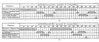
Change of oil
The oil in the hydraulic system is usually changed seasonally during maintenance or every 2000 operating hours. However, if low-quality oils are used, or if they are contaminated, an unscheduled replacement may be necessary.
This procedure consists of several important steps:
- Turn on the gear pump.
- Start the engine.
- Warm up the oil in the hydraulic system to 20-30 degrees.
- They turn off the engine.
- The oil is drained through the drain hole of the hydraulic tank after unscrewing the filler neck.
- Remove the filter and housing and wash it in diesel fuel.
- Reinstall the filter.
- Close the drain plug.
- Oil is poured through the filler neck to level “P” in the control window.
- Start the engine and bleed the hydraulic system by raising and lowering the hitch.
- If necessary, add oil to the tank.
Hydraulic distributor and its operating principle
A hydraulic system is a device for converting a small force into a significant force using some kind of fluid to transmit energy. The popularity of hydraulic systems is explained primarily by their high efficiency, reliability and relatively simple design.
Types of distributors in hydraulics
Depending on the type of control element when opening or closing, there are valve and spool valves in the World.
Spool and valve devices differ in the type of direct (manual, mechanical control, electrical, hydraulic, pneumatic control) and indirect action (electro-hydraulic control).
What is the main difference between a spool valve and a valve valve?
Valve distributors provide better tightness, and they are also able to operate at higher pressures.
Spool valves are compact; they also provide smoother overlap of working areas, which is especially important in the presence of large inertial masses.
Number of hydraulic valve positions
The number of options for connecting hydraulic lines with a distributor is called the position number. The most widespread are two- and three-position distributors.
Number of supplied hydraulic lines
Distributors can vary in the number of lines supplied, the most commonly used are four-line hydraulic distributors, 4 lines are supplied to them:
- p – pressure;
- t – drain;
- a—output to line A (for example, supplying fluid to the piston cavity of a jack);
- b - output to line B (for example, supply of working fluid to the rod cavity of the jack).
Why do you need a hydraulic arrow in a heating system?
It is very simple to explain why a hydraulic arrow is needed for heating. The processes of heat supply imbalance are familiar to owners of private houses. A modern boiler has a circuit that is smaller in volume than the consumer’s circulation flow. The operation of the heating hydraulic switch allows you to separate the hydraulic circuit of the heat generator from the secondary circuit, increasing the reliability and quality of the system.
The answer to the question: “Why is a hydraulic arrow needed in a heating system?” is a list of advantages of heating with a hydraulic thermal separator:
- separator is a mandatory condition of the equipment manufacturer to guarantee maintenance for a boiler with a power of 50 kW or more, or a heat generator with a cast iron heat exchanger;
- the unit ensures maximum flow with laminar coolant flow, maintains the hydraulic and temperature balance of the heating system;
- parallel connection of the heating water supply and the consumer circuit creates minimal losses of pressure, productivity and thermal energy;
- the knee arrangement of the supply and return pipes ensures a temperature gradient of the secondary circuits;
Scheme of coolant movement in a manifold with a hydraulic arrow.
- optimal selection and calculation of a hydraulic arrow for heating protects the boiler from the difference in supply and return temperatures, protects equipment from thermal shock, equalizes the circulation volume of water flows in the primary and secondary circuits;
- the unit increases the efficiency of the boiler, allows secondary circulation of part of the coolant in the boiler circuit, saves electricity and fuel;
- the mixture maintains a constant volume of boiler water;
- in case of emergency, the separator compensates for the flow deficit in the secondary circuit;
- the hollow separator reduces the influence of pumps with different kW power on the secondary circuits and the boiler;
- additional functions of a hydraulic separator - reduces hydraulic resistance, creates conditions for the separation of dissolved gases and sludge.
In multi-circuit heating systems, the use of a hydraulic arrow is mandatory for balanced operation.
The operating principle of the heating hydraulic arrow makes it possible to stabilize hydrodynamic processes in the system. Timely removal of mechanical impurities from the coolant will extend the life of pumps, valves, meters, sensors, and heating devices. By separating the flows (heat generator circuit and independent consumer circuit), the hydraulic arrow ensures maximum use of the heat of combustion of the fuel.
Hydraulic distributors types design operation marking
Hydraulic distributors are divided: according to the design of the shut-off and control element - into spool valves, tap valves and valve valves ; number of external hydraulic lines - two-line, three-line , etc.; the number of characteristic positions of the shut-off and control element - two-position, three-position, etc. ; type of control - for distributors with manual, mechanical, electrical and hydraulic control ; number of shut-off and control elements - single-stage, two-stage, etc.
The symbol of the hydraulic distributor (Fig. 1) indicates the number of its positions (I, II), external hydraulic lines (A, D R, T7) connected to the distributor, their connection, as well as the control method (GOST 2.871-68*).
The number of positions is represented by the corresponding number of squares (rectangles). The passages are depicted by straight lines with arrows showing the direction of flow of the working fluid in each position, and the junctions of the passages are marked with dots; a closed passage is depicted as a dead-end line with a transverse dash. External hydraulic lines lead only to the starting position. The method of controlling the distributor is indicated by signs adjacent to the ends of the distributor designation.
To imagine the operation of the hydraulic distributor in a certain working position, it is necessary to mentally move the designation square corresponding to this position to the place of the square of the original position, leaving the communication lines in the same position. Then the true directions of the flow of the working fluid will be indicated by the arrows in this square.
The symbols are the same for spool, valve and valve hydraulic valves, i.e. the symbol does not reflect the design of their shut-off and control elements.
In addition to graphic designations of hydraulic distributors, their digital designations are also given in the form of a fraction: the numerator indicates the number of external hydraulic lines connected to the hydraulic distributor, and the denominator indicates the number of its working (characteristic) positions. For example, a four-line three-position hydraulic valve is designated by the fraction 4/3 (see Fig. 1, d).
Shut-off and control elements (spool valve, tap, valve) in hydraulic control valves always occupy fixed positions according to the “fully open” or “fully closed” principle. Therefore, the hydraulic directional valve has virtually no effect on the pressure and flow rate of the working fluid passing through it.
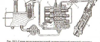
Position-force regulator
This mechanism combines devices for implementing both force and positional regulation. It is necessary to control the position of agricultural machines and devices from the operator’s seat. This regulator allows you to increase and decrease the additional load on the rear wheels of the tractor, change the amount of penetration of agricultural implements into the ground, and maintain this depth constant.
The use of the mechanism provides an increase in productivity and a reduction in diesel fuel consumption by approximately 10% compared to the use of GSV.