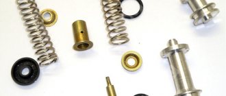
Adjusting the toe-in of the front wheels
Category - Front axle
The toe-in of the front wheels of the MTZ-80, MTZ-82 tractors, when adjusted at the factory, is set within 4-8 mm.
Periodically, every 240 hours of operation, as well as whenever the front wheel track changes, check and, if necessary, adjust the wheel alignment. Before checking alignment, be sure to check and, if necessary, adjust the clearances in the wheel bearings and steering rod joints.
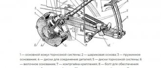
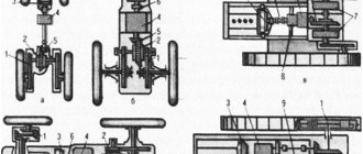
Scheme for adjusting the toe-in of the front wheels of the tractor
- 1, 9 — tractor wheels
- 2 - front axle
- 3, 5, 6, 8 — locknuts
- 4, 7 — right and left steering rod pipes
Adjust wheel alignment in the following order:
- Place the tractor on a horizontal platform with a hard surface.
- set the bipod to the middle position, for which press the dipstick 2 until it stops (Fig. *) and, turning the steering wheel, set it to the position where the dipstick is recessed as much as possible.
- check that the housings of the conical pairs (for tractors MTZ-82, MTZ-82L) or steering knuckles (for tractors MTZ-80, MTZ-80L) are extended to the same length “B” (Fig. above), respectively, from the front axle housing and front axle pipes.
- Adjust the left and right tie rods so that for both tie rods the distance “A” (fig. above) between the ball pins is the same. When changing the length of the tie rods, make sure that the bipod remains in the middle position (hold with the steering wheel). To adjust the length of the tie rods, loosen the lock nuts and, by rotating the left and right pipes, set the required length of the tie rods.
- Determine the wheel alignment by measuring the distance (dimension “D”) between the inner edges of the wheel rims in front (at the height of the wheel centers) and make chalk marks at the measurement points. Then drive the tractor forward so that the marks are at the same height at the rear, and measure the distance between the marked points (measurement “B”). The second measurement should be greater than the first, the difference between the second “B” and the first “D” measurements is equal to the wheel toe-in value and should be within 4-8 mm. If necessary, adjust the toe-in by changing the length of the steering rods. When adjusting the toe-in, lengthen or shorten the left and right rods by the same amount.
- again check the installation of the bipod in the middle position (according to probe 2, Fig. *) and the difference in dimensions “D” and “B”.
- Lock the tie rod tubes after final wheel alignment adjustment.
* see fig. "Power steering circuit and differential lock."
Interesting read:
tractor-mtz80-mtz82.ru
Toe adjustment
Correct installation ensures a stable position when driving straight, uniform wear of the front tires of the machine and comfortable handling. The front edges of the wheels are set at a slight angle inward to the axis of movement. For MTZ 80(82), the correct installation of the front wheels is especially important when using tractors for transport work on paved roads.
The alignment of the front wheels of the MTZ 80(82) tractor is checked every 240 working hours; if uneven tire wear is detected, immediate adjustments are made. A difference from the installation position of more than 15 mm is unacceptable. The reasons for the violation of convergence may be the appearance of backlash in the joints and deformation of the steering linkage parts, as well as as a result of repairs to the front axle or changes in the width of the front track.
Preparing the tractor
For successful adjustment, you need to check the compliance and make sure that:
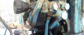
- tightening of nuts, pipes, pin and ball joints of steering rods and front axle
- tightening the hydraulic booster shaft bipod nuts
- fastening the nuts and bolts of the swing arms
- appropriate axial clearance of wheel bearings and tire pressure
- the distance between the steering knuckles B and the front axle pipes in MTZ 80 or the wheel reducers and the FDA housing in MTZ 82 on both sides must be the same
Convergence installation process
The position is checked in the following order:
- The tractor is rolled out onto a flat area with a hard surface with the wheels in the position corresponding to straight-line movement.
- Measure the distance between the edges of the rim-discs from the rear side at the level of the center of the axis of rotation of the wheels with the measuring bar in a horizontal position.
- The locations of the measurement points are marked with chalk.
- Roll the tractor forward about 1.5 meters so that the marks with the wheels turning 180˚ are in front of the axis of rotation and also make a second similar measurement in its center.
Measurements without rolling the wheels are not allowed, as the measurements will be incorrect due to the existing runout of the rims.
To take measurements, use a measuring telescopic bar or rod. The device can be made from two parts of even wooden planks or metal pipes that fit into one another with clamps that fix the length. A scale is applied to one of the parts of the measuring device. To check the toe-in of MTZ 80(82) tractors, it is enough to change the length of the bar from 1200 to 1800 mm, taking into account the limits for adjusting the width of the front track.
Incorrect adjustment of the wheel alignment angles of the vehicle can cause problems with its controllability, as well as premature wear of the tires. Normal elements ensure transport stability and the correct trajectory of movement. This article will discuss the installation of MTZ 80 wheel alignment, its sequence and basic principles of operation.
Adjusting the tractor track
Category - Front axle
The tractor track can vary from 1200 to 1800 mm. (1500-1900 mm for MTZ-82, MTZ-82L) along guide wheels and from 1400 to 2100 mm. on drive wheels, which allows you to work in all standard row spacings of row crops.
The track of the front wheels of the MTZ-80 and MTZ-80L tractors is adjusted at intervals of 100 mm. with symmetrical and 50 mm. with asymmetrical wheel arrangement. To set the required guide wheel track, perform the following operations:
- lift the front part of the tractor with a jack until the wheels lift off the ground.
- loosen the bolts, remove pins 24 securing the retractable knuckles in the front axle pipe (see Fig. “Front axle of the tractor”).
- first move one and then the other retractable cam (at the same time change the length of the steering rods by rotating the pipes 25 in the tips) by an amount corresponding to the track being installed, then secure the cams in the front axle pipe.
- when setting the track to 1400 mm. and more than 25 steering rod pipes must be replaced with extended ones (attached to the tractor spare parts).
- lower the tractor. Check and, if necessary, adjust wheel alignment.
The track of the front wheels of the MTZ-82, MTZ-82L tractor is infinitely adjustable by a screw mechanism located on the front axle arms (Fig. 113) in three intervals (Fig. 112): 1200-1500 mm, 1500-1600 mm, 1600-1800 mm. To change the track, lift the front part of the tractor (or the front wheels one by one), ensuring clearance between the wheels and the ground, and brake the rear wheels.
Adjusting the track of tractors MTZ-82 and MTZ-82L (Fig. 113)
- screw
- pad
- wedges
- Tread control cover (removed)
To install wheels on a track width of 1500-1600 instead of 1200-1500 (or vice versa), unscrew the nuts securing the wheel rim to the disk and turn the wheel so that the rim brackets pass through the slots into the disks. Depending on the required track width, set the appropriate relative position of the wheel rim relative to the disk as shown in Fig. 112.
To obtain a track within 1600-1800 mm. remove the wheels from the rims and swap them, that is, place the left wheel on the right side, the right wheel on the left (see Fig. 112). At the same time, make sure that the direction of rotation of the tire remains the same (along the arrow indicated on the sidewall).
Diagram of installation of the front wheels of the MTZ-82 and MTZ-82L tractors on different tracks (Fig. 112)
When changing the track by moving the rim on the disk and the wheels from one side to the other, change the position of the wings accordingly by changing the wing mounts. For this purpose, there are additional holes in the brackets and wing supports.
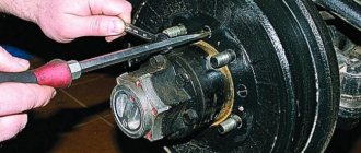
To change the track width using a screw mechanism (Fig. 113), do the following:
- loosen the bolts, move and remove the cover 4.
- release the wedges of the 3 sleeves by unscrewing the nuts enough to ensure free movement of the bodies of the conical pairs.
Rotating the adjusting screw using a wrench ensures that the final drive housings with wheels move in the front axle sleeves and obtain the required track at the specified intervals. Rotation of the adjusting screw should be accompanied by a change in the length of the steering rods. On the left and right bodies of the upper conical pairs there are marks with a digital designation of the most common gauge sizes: 1350, 1400, 1500, 1600, 1800 mm.
After changing the track, be sure to re-adjust the toe-in of the front wheels.
To change the rear wheel track, perform the following operations:
- lift the rear part of the tractor with a jack until the wheels lift off the ground; Unscrew the fastening bolts and remove cover 1 (see Fig. “Drive wheels”) of the worm.
- Unscrew the bolts 8 securing the liner to the hub of one of the wheels 2-4 turns and clean the axle shaft from dirt.
- Rotating worm 2, move the wheel until the required track is obtained, after which tighten the bolts securing the liner to capacity and install the worm cover in place.
- set the second wheel to the required position.
Up to 1600 mm. the track is obtained without rearranging the wheels.
To obtain a gauge over 1600 mm. rearrange the wheels (see figure below).
Rear wheel track adjustment diagram
- Size “A”: 1400-1600 for (15.5-38) R; 1250-1600 for 9-42
- Size “B”: 1800-2100 for (15.5-38) R; 1800-2100 for 9-42
Interesting read:
tractor-mtz80-mtz82.ru
Optional equipment
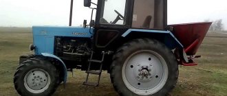
One of the main advantages of these models of row-crop equipment is the presence of an aggregate system of separate mounted installations equipped with a hydraulic lift. Such a system provides power, height and combined adjustment of working equipment and its position. The design of MTZ-921 tractors includes traction elements to which working tools and technical equipment for agricultural and municipal purposes are attached. For attachments, the NU-2 lifting device is used, which can withstand a weight of 1500-4000 kg, and for traction and clutch, the TCU-1B traction fork model is used. Thus, the technical equipment of the MTZ-921 allows the model to be equipped with the following types of attachments:
- plows and harrows used in the process of row-crop work;
- plow blades installed in front of the tractor and intended for clearing roads;
- road brushes, which indicates the use of these technical means in public utilities with
- for the purpose of cleaning the street space from dirt, debris, snow or leaves;
- loading equipment installed in front of the MTZ-921 tractor and intended for
- carrying out loading and unloading operations;
- screw-rotor cleaners designed to clear roads from dirt and snow by throwing or
- by loading it into a specialized container.
Thanks to the wide range of additional equipment that can be installed, the MTZ 921 models are indispensable in public utilities and agriculture, in the livestock sector and construction. Their main advantages are: high power, fuel efficiency, maneuverability, maximum operator comfort and ease of operation.
Wheel alignment of the MTZ 82 tractor and its adjustment :: MTZ-82 tractor
Wheel alignment of the MTZ 82 tractor and its adjustment
» Chassis and steering » Wheel alignment of the MTZ 82 tractor and its adjustment
For more stable movement of the tractor, easy control and maneuvering, and proper tire wear, there are certain requirements for the angles of inclination of the king pins and wheels in relation to the tractor frame.
Adjusting the camber of the front wheels of the MTZ 82 tractor consists of the correct position in the vertical plane and toe in the horizontal and, in addition, the inclination of the pins in the longitudinal and transverse planes.
The camber angle is determined by a vertical plane, which is parallel to the longitudinal axis of the tractor and the plane of the wheel α. Wheel camber creates forces during tractor movement, which force the wheels to press against the inner bearings of the hubs. If this force were absent, then the wheel, with a small axial clearance in the bearings, would be in an unstable position, pressing either against the outer or inner bearing. The movement of the wheel along its axis would cause the upper part of the tractor to swing, as a result of which the wheel bearings would wear out much faster, and would also cause instability in the stability of movement.
Camber and toe angles of the front wheels: α — camber angle; β is the angle of inclination of the king pin to the side; γ is the angle of inclination of the king pin forward; h—rolling shoulder.
Among other things, the inclined placement of the wheels reduces the effort required to maneuver the tractor. The camber angle of the MTZ 82 tractor is 3.5º.
The transverse inclination of the kingpin is determined by the angle β between the vertical plane parallel to the longitudinal axis of the tractor and the axis of the kingpin. The correct lateral inclination of the kingpin promotes stable straightness of the wheels. While turning the wheels, turning around the kingpins, the position of which is inclined relative to the vertical plane of the tractor, lifts its front part. As a result, the turned wheels will always tend to the middle position. The angle β for the MTZ 82 tractor is 7º.
The longitudinal inclination of the kingpin is determined by the angle γ between the plane perpendicular to the longitudinal plane of the tractor and the axis of the kingpin. If the lower part of the king pin is tilted forward, then the angle γ is called positive, and if it is tilted backward, it is called negative. Increasing the positive lean angle causes increased cornering resistance and increases the tendency of the wheels to return to the center position. When the negative angle increases, the opposite process occurs.
The toe-in of the wheels of the MTZ 82 tractor is determined by the difference in the distances between the side parts of the tires in front and behind, when viewed from above, at the height of the central part of the wheels (L1>L2), the presence of toe-in forces the wheels to roll inside the tractor, which promotes uniform wear of the tires and improves the stability of the tractor.
Adjusting the camber and toe of the MTZ 82 tractor
During operation of the tractor, wheel alignment may be disrupted due to wear or deformation of the steering linkage components, after dismantling the front axle or changing the track width of the front wheels.
Ruler rod for measuring toe-in of front wheels
Before checking the wheel alignment, you need to make sure there are no gaps in the steering. To do this, you need to check the tightness of the pipes and ball pins of the steering rods, nuts, bolts and nuts of the swing arms, as well as the nuts of the power steering shaft bipod. Check tire pressure and axial movement of bearings.
Place the tractor on a flat surface in a position similar to straight-line movement and, using a rod with a measuring ruler, measure the distance between the rear inner edges of the wheel rims at the height of their centers. The bar is placed in a horizontal position, and the points of contact with the rims are marked with chalk. Next, the tractor rolls forward until the wheels turn 180º (about 1.5 m) so that the marked marks on the rims appear at the same height and repeat the measurement. The distance between the marks on the rims at the rear (L1) should be 4 millimeters greater than at the front (L2). If the convergence is greater, then it is necessary to shorten the steering rods, and if less, lengthen them equally on both sides.
13.08.2018
tractor-mtz82.ru
How to install camber and toe on T-40 am
Ivan Storodov April 23, 2022 Rustam Abulkaramov April 23, 2022 Ivan Koptev Rustam Abulkaramov April 23, 2022 Rustam Abulkaramov Rustam Abulkaramov April 23, 2022 Anton Bolshakov April 23, 2019
Related Posts
Why at T 40 am. Power steering not working?
- Author: Azat Fakkarov
- July 08, 2020
- 3 comments
Hello everyone. T 40 am. It’s as if the power steering is not working. What is the reason, maybe someone has encountered it. Thank you.
Which is better for the T-40 AM mower, rotary or segmented?
- Author: Alexander Grenkov
- April 16, 2020
- 44 comments
Good afternoon, can you recommend a T-40 AM hay mower? Rotary or segmental? Thanks in advance.
Can the T-40 AM carry such a weapon?
- Author: Vladimir Potemkin
- February 28, 2020
- 54 comments
Brothers tractor drivers! Please tell me if the T 40 AM can have such a weapon
I installed a completely new power steering on the T-40AM tractor, and the steering wheel began to turn much harder.
- Author: Ilya Dits
- September 15, 2019
Tell me, please: I installed a completely new power steering on the T-40am tractor, and the steering wheel began to turn much harder. Tractor with KUHN, pump NSh-32, steering everything is injected. Could there be problems because of the pressure valve, which is sealed on the power steering, or because of something else? Thanks everyone.
Need reviews. Which tractor is better to buy for yourself: T-40 AM or MTZ 82?
- Author: Kostya Glavatskikh
- 09 August 2019
- 222 comments
Need feedback, please help. Which tractor is better to buy for yourself: T-40 AM or MTZ 82? Photo to attract attention. Thanks in advance for your opinions!
T-40am
- Author: Nikolay Drobyshev
- May 17, 2019
Why does the front axle jam in 5th and 6th gear on the T-40 AM tractor. The right side is pulling!
- Author: Oleg Vinokurov(admin)
- May 04, 2019
Hello, friends! Please tell me who may have had the problem that the front axle on the T 40 am tractor jammed. Previously, this happened when you were driving in 6th gear, but now it starts to jam in 5th! The right side is pulling! [id373578351|Ilgiz Yakupov]
What kind of oil should I put in the T-40 for the winter?
- Author: Yuri Tikhonov
- September 28 10:10
Good morning. Guys, what kind of oil do you use for the winter? T-40
T-40am. Why does the steering wheel turn to the left, but not to the right?
- Author: Danil Belikov
- 22 September 21:10
Guys, the problem is this: on the T40am the steering behaves strangely, initially everything was fine. Now the steering wheel turns to the left, but not to the right. I can’t understand anything. Thanks in advance for the advice.
Tractor T-40 am. Why did the pressure in the tractor hydraulic system disappear?
- Author: Oleg Vinokurov(admin)
- 19 September 13:10
Good afternoon. Friends, tell me. Tractor T-40 am. The pressure in the tractor hydraulic system has lost. Has anyone encountered this problem? We unscrewed the tube from the distributor, oil from the pump does not flow there. The drive was disassembled. The balls fell out. Who collected them back? How can we prevent this situation from happening again? .. Alexander.
MTZ 82 tractor wheels - front and rear :: MTZ-82 tractor
MTZ 82 tractor wheels - front and rear
» Chassis and steering » MTZ 82 tractor wheels - front and rear
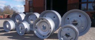
The MTZ 82 tractor wheel consists of a rim with a hard disk attached to it and a pneumatic tire mounted on the rim. The wheel rim acts as a base, thanks to which the tire, inflated with compressed air, transfers the load to the soil. The wheel is attached to the hub using a disc.
The wheel rim is made of steel sheet, rolled by rollers to form a special profile and then weld the joint around the circumference, which makes it non-dismountable.
Front and rear wheel disc
The front and rear wheel disks of the MTZ 82 tractor are welded to the rim. The front wheel discs are connected using bolts to brackets welded to the rim. This design allows for mutual replacement of the location of the rim and disk, and also allows for adjustment of the front wheel track. To enhance the strength of the rear wheel disks, a reinforcing ring is welded to the place where they are attached to the hub.
Rear drive wheel of the MTZ 82 tractor: 1 - screw cover; 2 - bolt; 3 - adjusting screw; 4 — hub liner; 5 — axis of the adjusting screw; 6 — hub; 7 - bolt; 8 — ballast weight; 9 — rim; 10 - tire; 11 - nut; 12 — ballast weight fastening bolt; 13 — hub bolt; 14 - spherical washer; 15 - key.
Rear wheel hub
The rear wheel hub is installed on the protruding end of the rear axle final drive axle shaft using a bushing, a key and four bolts. The liner is equipped with an adjusting screw that engages with a gear rack cut into the axle shaft. By turning the screw with a wrench, it is possible to move the hub together with the wheel relative to the axle shaft and continuously change the track width of the rear wheels.
The flanges of the front and rear wheel hubs have bolts on which the wheel rims are mounted. To prevent screwing of the nuts, deep conical chamfers are used on the nuts and in the holes of the disks.
Twin wheels
To improve the traction and grip properties of the tractor, when performing field work on soils with high humidity, it is possible to install dual wheels on the rear axle shaft using a spacer. When installing spacers, a bolt is mounted into the rear wheel hub, the length of which is 35 millimeters longer than usual. The inner wheel is mounted on an extended bolt and tightened with nuts. Next, a spacer is installed on these bolts, which is secured to the bolts with nuts. The outer wheel is installed on bolts mounted in the spacer flanges and tightened with nuts.
Installation of double wheels on MTZ 82: 1, 3 and 5 - nuts; 2 - bolt; 4 - extended bolt; 6 — spacer.
Wheel maintenance
It consists of monitoring the reliability of fastening connections and timely elimination of detected faults. When running in the tractor, it is necessary to check the tightness of the rear wheel hub bolts, the front wheel disc support bolt nuts and the rear and front wheel disc flare nuts every 240 hours of work.
The nuts are tightened evenly using the same force. Then make sure that the chamfers of the flare nuts fit snugly into the conical holes of the disk. Weak tightening can cause cracks in the holes and thread damage, which will inevitably lead to the disk and bolts becoming unusable. Unusable bolts must be promptly replaced with new ones. It is not recommended to carry out work on a tractor with an incomplete set of bolts on the disc, as this may damage the remaining bolts and break the rim or disc brackets.
13.08.2018
tractor-mtz82.ru
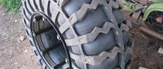
Tires for MTZ 82
Tires for tractors are selected based on operating conditions. Tractors from the Minsk Tractor Plant (MTZ) are universal and are used very widely: when clearing snow on the streets, plowing fields and harvesting, etc. Accordingly, there is no universal version of “rubber” for them. It all depends on how exactly the equipment will be used: on what soil, in what speed mode, etc. The model also plays a role - it is obvious that a heavy tractor needs larger and more durable tires than a compact minivan, and the pressure is MTZ 82 tires will be different than in the inner tubes of a forestry tractor type L82.2. Kits for the front and rear axles are selected separately.
Types of wheels
To choose and buy tires correctly at MTZ, you should understand the design of tractor tires. They are made of the chamber type, that is, they have an inner tube and tires. The chamber holds the air and takes on most of the load. The tire protects the tube from friction and consists of the following elements:
- Frame - made of cord, especially durable rubberized fabric, laid on top of each other in several layers. It is the characteristics of the cord that determine the strength of the tire and its load-carrying capacity.
- The inner layer of soft rubber is called a breaker and acts as a shock absorber for impacts received by the tread.
- The tread is the outer layer of durable rubber formed on the carcass and is responsible for the tire's grip on the ground. The adhesion parameters depend on the shape and depth of the pattern formed by the lugs and depressions.
- Sidewalls are used to protect the side walls of the frame. The beads secure the tire to the wheel rim and also increase the rigidity of the beads due to wire rings inside.
Adjusting the track of the front and rear wheels of the MTZ 82 tractor :: MTZ-82 tractor
Adjusting the track of the front and rear wheels of the MTZ 82 tractor
» Chassis and steering » Adjusting the track of the front and rear wheels of the MTZ 82 tractor
Rear wheel track adjustment
The track adjustment is carried out steplessly on narrow tires 9-42 in the range of 1350-1800, and on wide tires 15.5-38 in the range of 1400-2050 millimeters by moving the wheel hubs along the protruding ends of the rear axle axles using screw mechanisms, as well as by rearranging wheels together with hubs from side to side.
In order to change the track width of the rear wheels of the MTZ 82 tractor, perform the following steps:
1. lift the rear part of the tractor with a jack so that the wheels are raised above the surface; 2. remove the cover of the screw mechanism, unscrew the bolts securing the liner to the hub by 2-4 turns and remove dirt from the axle shaft; 3. Rotating the worm, move the hub together with the wheel along the axle shaft to the required track, then tighten the hub bolts until they stop and install the worm cover; 4. in order to set the track width to more than 1600 mm, install the wheel so that the convex side of the disks “looks” towards the rear axle axle sleeves. To maintain the correct direction of tire rotation, swap the left and right wheels.
Diagram of installation of the front wheels of the MTZ-82 tractor on different tracks: 1 - rim; 2 — disk; 3 - bolt; 4 - nut; 5 — bracket.
Adjusting the track of the front wheels of the MTZ 82 tractor
The track of the front wheels changes steplessly by moving the wheel gears relative to the front axle sleeves using screw mechanisms, as well as by changing the relative placement of the disk and wheel rim.
The track is adjusted in this sequence:
1. using a jack, lift the front part of the tractor, or the front wheels in turn, so that they do not touch the surface; 2. remove the covers of the adjusting screws, unscrew the nuts and release the wedges of the front axle sleeves so that the housings of the upper bevel pairs of wheel reducers can move freely; 3. Rotating the screws using a wrench, move the wheel gears with the ends of the sleeves until the numbers and marks indicating the required track width on the housings of the upper bevel pairs match. In order to maintain the alignment of the front wheels, it is necessary to simultaneously change the length of the steering rods; 4. tighten the nuts of the front axle sleeve wedges; 5. Check the wheel alignment after changing the front wheel track.
13.08.2018
tractor-mtz82.ru
Advantages and disadvantages
Effective design solutions in Belarus 921 are:
- reduced overall height and width, making it possible to operate the tractor in rooms with low and narrow doorways;
- low center of gravity, allowing the use of equipment in difficult terrain;
- the engine meets the environmental requirements of the EURO-2 standard;
- The hydraulic attachment mechanism is designed for installing various attachments.
Among the disadvantages of the Belarus tractor, the following can be noted:
- impossibility of aggregation when the total load on the axles exceeds the maximum permissible weight of the tractor;
- impossibility of switching on the synchronous drive at tractor speeds above 8 km/h;
- light weight of the tractor, compensated by excellent maneuverability.