Lubrication system on KamAZ
The KamAZ 740 engine lubrication system of Euro-2, -3 and -4 classes is a whole complex of equipment for storing and delivering oil to the elements of the power unit, cleaning and cooling the lubricant:
- Engine oil pan: a trough-shaped container, divided from the inside into two parts. An oil intake is provided in the deep part of the pan. To ensure that oil is delivered to the oil intake without interruption, the pan is equipped with a partition. The pan cools the oil due to contact with the walls and heat exchange between the walls and the environment. The pans of new engines are equipped with one drain hole, old ones - with two.
- Oil intake: this part is located in the deep part of the pan and is used to deliver oil to other components of the power unit. The oil intake is equipped with a coarse filter and a tube connected to the oil pump.
- Oil pump: equipped with a fine filter, provides an optimal level of pressure to deliver oil to the main line.
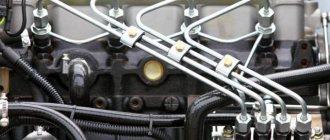
- Oil lines: through them, oil is delivered to the rubbing parts of the engine - the compressor, connecting rod bearings, etc.
- Oil cooler: this element of the system is responsible for cooling lubricants at air temperatures above 0 ° C. If the ambient temperature is below 0 °C, the oil cooler is switched off.
- Breather: Through ventilation, it removes the resulting fuel vapors and exhaust gases, preventing lubricant dilution.
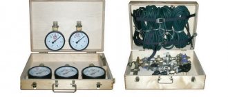
- Monitoring equipment and sensors: this is modern equipment that notifies the driver about the pressure level in the lubrication system, its emergency drop and clogging of the full-flow filter.
- Centrifugal filter: cleans the oil from foreign components. Under pressure, the rotor causes the oil to move; after cleaning, it flows into the radiator or, through the drain valve, into the oil pan.
Modern KamAZ 740 engines use the following principle of the lubrication system: oil is delivered to parts with the highest load under pressure, to others - by gravity or injection.
Properly selected oil of the required viscosity and high quality will extend the life of KamAZ engine components and stabilize its temperature during overloads.
_______________________________________________________________________________
Lubrication, air and exhaust systems of the Kamaz-740 diesel engine
Lubrication system Kamaz-740 The lubrication system Kamaz-740 is combined, with a “wet” sump. Pressurized oil is supplied to the crankshaft main and connecting rod bearings, camshaft bearings, rocker arm bushings, high-pressure fuel pump and compressor bearings. A pulsating oil supply is provided to the upper spherical supports of the pusher rods.
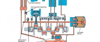
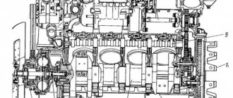
Rice. 1. Kamaz-740 engine lubrication system 1 - compressor; 2 — high pressure fuel pump; 3 — fluid coupling switch; 4 - fluid coupling; 5,12 - safety valves; 6 — lubrication system valve; 7 — oil pump; 8 — bypass valve of the centrifugal filter; 9 — centrifugal filter drain valve; 10 — oil radiator valve; 11 — centrifugal filter; 13 — warning lamp that the oil filter is clogged; 14 — oil purification filter bypass valve; 15 — oil purification filter; 16 — oil receiver; 17 — crankcase; 18 - main highway; A - to the radiator The lubrication system of the Kamaz-740 engine includes an oil pump, an oil crankcase, filters - full-flow and centrifugal, an air-oil radiator, oil channels in the block and cylinder heads, the front cover and the flywheel housing, external oil lines, an oil filler neck, valves to ensure normal operation of systems and control devices. The diagram of the Kamaz-740 lubrication system is shown in Fig. 1. From the crankcase 17 through the oil receiver 16, oil enters the discharge and radiator sections of the oil pump 7; from the injection section through a channel in the right wall of the block it is supplied to the oil purification filter 15, where it is cleaned by two filter elements, then enters the main line 18, from where it is directed through the channels in the block and cylinder heads to the crankshaft main bearings, rocker arm bushings and upper tips push rods. Oil is supplied to the connecting rod bearings of the Kamaz-740 crankshaft through holes inside the shaft from the nearest main journal. The oil removed from the cylinder walls by the oil scraper ring is discharged into the piston and lubricates the piston pin supports in the bosses and the connecting rod upper head bearing. Through the channels in the rear wall of the cylinder block and the Kamaz-740 flywheel housing, oil under pressure flows to the bearings: compressor 1, through the channels in the front wall of the block - to the bearings of the high-pressure fuel pump 2. Provision is made for oil to be taken from the main line for supply to switch 3 of fluid coupling 4, which is installed on the front end of the unit and controls the operation of the fluid coupling of the fan drive. From the radiator section of the Kamaz-740 oil pump, oil flows to centrifugal filter 11, then into the radiator and then drains into the crankcase. When tap 10 is closed, oil from the centrifugal filter is drained into the crankcase through drain valve 9, bypassing the radiator. The remaining engine parts and assemblies are lubricated by splash and oil mist. The Kamaz-740 oil pump (Fig. 2) is mounted on the lower plane of the cylinder block. The pressure section of the Kamaz-740 oil pump supplies oil to the main line of the engine, the radiator section supplies oil to the centrifugal filter and radiator. In the housings of sections 1 and 5, safety valves 11 and 18 are installed, adjusted to an opening pressure of 833.6...931.7 kPa (8.5...9.5 kgf/cm2) and designed to limit the maximum pressure at the outlet of the pump sections. Valve 14 of the lubrication system of the Kamaz-740 engine, triggered at a pressure of 392.4…441.31 kPa (4.0…4.5 kgf/cm2), is designed to limit the pressure in the main line of the engine.
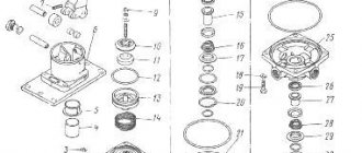
Rice. 2. Oil pump KamAZ-740 1 - radiator section housing; 2 — driving gear of the radiator section; 3 - spacer; 4 — driving gear of the discharge section; 5 — housing of the discharge section; 6 — driven gear of the pump drive; 7 - key; 8 — drive gear shaft; 9 — driven gear of the discharge section; 10 — driven gear of the radiator section; 11 — safety valve of the radiator section; 12, 15, 17 — valve springs; 13, 16 — valve plugs; 14 — lubrication system valve; 18 - safety valve of the discharge section The Kamaz-740 oil purification filter (Fig. 3), installed on the right side of the cylinder block, consists of a housing 19, caps 24 and two paper filter elements 23. A bypass valve 16 is installed in the Kamaz-740 filter housing indicator of filter element clogging. The warning light for filter element clogging is located on the instrument panel in the cockpit. The lamp is allowed to glow or blink when starting and warming up the engine. If the lamp is constantly lit on a warm engine, replace the filter elements. In the Kamaz-740 filter housing there are oil pressure sensors and alarms for an unacceptable decrease [less than 68.7 kPa (0.7 kgf/cm2)] of oil pressure in the main line. The bypass valve allows crude oil to pass into the main line, bypassing the filter element, at low oil temperatures or significant clogging of the filter elements with pressure drops across the elements of 245.8... 294.2 kPa (2.5... 3.0 kgf/cm2). Rice. 3. Oil filter KamAZ-740 1 – rod; 2 — retaining ring; 3, 7 — washers; 4 - sealing ring; 5 - cap spring; 6 — sealing cup; 8 – bypass valve spring; 9 — alarm screw; 10 — bypass valve plug; 11, 18, 20, 26 gaskets; 12 — adjusting washer; 13 — signaling device body; 14 — movable contact of the signaling device; 15 — signaling device contact spring; 16 — bypass valve; 17- plug; 19 — filter housing; 21 — housing bushing; 22 — sealing ring; 23 — filter element; 24 — cap; 25 - drain plug Kamaz-740 centrifugal oil filter (Fig. 4) - with an active-reactive rotor drive, installed on the front cover of the cylinder block on the right side of the engine. The rotor assembly with the cap is driven into rotation by a stream of oil flowing from a tangential slot in the rotor axis, as well as by reactive forces arising when the oil enters the tangential channels of the rotor. When the Kamaz-740 engine is running, oil from the radiator section of the pump is supplied under pressure to the filter, ensuring rotation of the rotor. Under the action of centrifugal forces, mechanical particles are thrown to the walls of the rotor cap and retained, and the purified oil enters the air-oil radiator through the hole in the rotor axis and tube 17 or through the drain valve in the filter housing, adjusted to a pressure of 49.0 ... 68.7 kPa (0.5... 0.7 kgf/cm2), into the engine crankcase. The bypass valve installed in the Kamaz-740 filter housing is adjusted to a pressure of 588.4...637.5 kPa (6.0...6.5 kgf/cm2). Fig.4. Centrifugal oil filter KAMAZ-740 1 - housing; 2 - rotor cap; 3-rotor; 4- filter cap; 5 — nut for fastening the rotor cap; 6 – thrust ball bearing; 7 – thrust washer; 8 — rotor mounting nut; 9 — nut for fastening the filter cap; 10 — upper rotor bushing; 11 — rotor axis; 12 — screen; 13 — lower rotor bushing; 14 — stopper finger; 15 — stopper plate; 16 — stopper spring; 17 — oil drain pipe In order not to disturb the balancing of the rotor when servicing the filter, there are marks on the rotor and the cap that must be aligned when assembling it. The Kamaz-740 steel stamped oil crankcase is secured to the lower plane of the cylinder block with bolts. A rubber-cork gasket is installed between the crankcase and the block to ensure a tight connection. There is a drain plug in the lower part of the Kamaz-740 crankcase. Air-oil radiator, tubular-plate, double-row, air-cooled, installed in front of the radiator of the Kamaz-740 cooling system. Air system and gas exhaust system of Kamaz-740 The air system of Kamaz-740 is designed to take air from the atmosphere, clean it from dust and distribute it among the cylinders. The diagram of the Kamaz-740 air system is shown in Fig. 5. Atmospheric air is sucked into the engine cylinders, passing through the air cleaner 25.
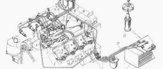
Rice. 5. Air system and gas exhaust system Kamaz-740 1 - gas breather pipe; 2 — breather; 3 — oil drain pipe of the breather; 4 — engine intake air duct; 5 — air cleaner; 6 — exhaust manifold; 7 — outlet pipe; 8 — muffler; I - air from the atmosphere; II - purified air; III - crankcase gases; 1V - exhaust gases Purified air is distributed by the intake manifolds throughout the engine cylinders and participates in combustion as part of the working mixture. Exhaust gases pass through the exhaust manifolds, exhaust pipes of the muffler and are released into the atmosphere through the muffler. Gases that have penetrated into the engine crankcase through the gaps between the cylinder mirror and the piston rings are removed into the atmosphere through the pipe and exhaust pipe due to excess pressure. In Fig. Figure 6 shows Kamaz-740 air systems used on various car models of the Kama Automobile Plant. Air is taken into the engine through the air intake. Rice. 6. Diagram of air intake systems for Kamaz vehicles a - Kamaz-5320 and 55102, b - Kamaz-53212, 5410 and 54112, c - Kamaz-55111, 1 - cap; 2 — air intake pipe; 3 — seal: 4 — air cleaner; 5 - bracket (arrows indicate places subject to tightness control when servicing the system) In the Kamaz-740 air system, between the air intake pipe and the air ducts attached to the engine, there is a seal - a corrugated rubber pipe, inside of which a pressure disk is inserted, which serves as a support for the spacer spring. The latter ensures the tightness of the connection between the seal and the air intake pipe during the transport position of the cabin. The air cleaner of the air system (Fig. 6, a) of Kamaz-5320 and Kamaz-55102 vehicles is attached to the left frame side member. On other vehicles (Fig. 6, b and c), the air cleaner is mounted on bracket 5. The Kamaz-740 air cleaner is dry type, two-stage. The first centrifugal stage is a monocyclone with collection of separated dust into a hopper, the second stage is a paper filter element. The Kamaz-740 air purifier (Fig. 7) consists of a housing 8, a filter element 5, a cover 1 attached to the housing with four latches. Rice. 7. Air purifier KamAZ-740 1 - cover; 2 — cover gasket; 3 - body; 4 — dust trap; 5 — filter element; 6 - filter element nut The tightness of the connection is ensured by gasket 2. In the internal cavity of the cover there is a partition with a slot and a plug, which forms a dust collection cavity (hopper). There is a dust separator 4 at the inlet pipe of the air cleaner. The filter element is secured in the housing with a self-locking nut 6.
Installation of Kamaz-740 air purifiers a) with cabs without a berth; b) with cabins with a berth; 1-bracket; 2-air purifier; 3-spring stop; 4-seal; 5- spacer spring; 6-pressure disc; 7-adapter; 8-pipe; 9-air intake hood; 10-cabin; 11 - connecting pipe of the intake manifold; 12-device “Winter-summer”; The sucked air enters the filter through the inlet pipe. The Kamaz-740 dust separator creates a rotational movement of the air flow in the annular gap between the housing and the filter element; due to the action of centrifugal forces, dust particles are thrown towards the wall of the housing and collected in the hopper through a gap in the partition. The pre-cleaned air then passes through the filter element, where it is finally cleaned. To clean the hopper from dust, remove the cover, remove the plug from the hole in the partition, remove dust and wipe the hopper. The cover should be installed so that the arrow on the bottom is directed upward when the filter is positioned horizontally (KAMAZ-55111, KamAZ-5410, KamAZ-54112 vehicles). Clean air from the Kamaz-740 air cleaner enters the engine intake manifolds. To increase the efficiency of cleaning the air entering the engine and increase the service life of the filter element, a pre-cleaner is installed in the air cleaner (Fig. 8). Rice. 8. Installation of pre-cleaner Kamaz-740 1 - tightening laces; 2 - pre-cleaner; 3 - filter element The Kamaz-740 pre-cleaner is a shell made of non-woven filter fabric, which is put on the filter element before installing it in the filter housing. The Kamaz-740 intake air ducts are fixed on the side surfaces of the cylinder heads on the camber side with bolts through sealing paronite gaskets and connected to the inlet channels of the cylinder heads. The Kamaz-740 inlet air ducts of the left and right halves of the block are connected to each other by a connecting pipe. The pipe is secured to the flanges of the air ducts with bolts. The connections between the pipe and the intake air ducts are sealed with rubber gaskets. The air system of the Kamaz-7403 engine differs from the Kamaz-740 engine in the installation of an air cleaner, the design of air ducts, intake manifolds and pipes. Clean air from the air cleaner is supplied through a tee to two centrifugal compressors and, under an excess pressure of 70 kPa (0.7 kgf/cm2) in maximum power mode, is supplied through the intake manifolds to the cylinders. The connection of the air supply tee to the compressors and Kamaz-740 compressors to the intake manifolds is ensured by rubber pipes and hoses, which are tightened with clamps. The Kamaz-740 air cleaner clogging indicator (Fig. 9) is installed on the instrument panel and is connected to the engine intake manifold with a rubber hose. Rice. 9. Air cleaner KamAZ-740 clogged indicator 1 - disk; 2 - signal drum When the maximum vacuum in the engine intake manifolds reaches 6.86 kPa (0.07 kgf/cm2), the indicator is triggered - the red section of the drum closes the indicator window and remains in this position after the engine is stopped. This indicates that the air purifier needs servicing. Kamaz-740 exhaust gas system The Kamaz-740 exhaust gas system (Fig. 10) is designed to release exhaust gases into the atmosphere.
Rice. 10. Kamaz-740 exhaust system 1 – connecting pipes; 2 – tension flanges; 3 – turbochargers; 4, 8 – exhaust pipes; 5 – muffler; 6 – muffler mounting brackets; 7 – frame spar The Kamaz-740 gas exhaust system consists of two exhaust manifolds 9, two exhaust pipes 7 and 8, a flexible metal hose 5, a muffler 1. Each exhaust manifold serves a row of cylinders and is attached to the cylinder block with three bolts. Kamaz-740 manifolds are connected to the cylinder heads by pipes. The detachable design of the manifold-pipe-head connection makes it possible to compensate for thermal deformations that occur during engine operation. The Kamaz-740 intake pipes are united by a tee and connected to the muffler by a flexible metal sleeve, which compensates for assembly errors and temperature deformations of system parts. A damper for the auxiliary engine brake system is installed in each downpipe. The Kamaz-740 exhaust noise muffler (Fig. 11) is active-reactive, non-separable design. An active muffler operates on the principle of converting sound energy into thermal energy, which is carried out by installing perforated partitions in the path of gases, in the holes of which the gas flow is crushed and the pulsation is damped. Rice. 11. Kamaz-740 noise muffler exhaust 1 - perforated pipe; 2 — thrust flange; 3 — tension flange; 4 - front wall; 5 — body; 6 — outlet pipe; 7 - rear wall The Kamaz-740 reactive muffler uses the principle of acoustic sound filtration. This muffler consists of a series of acoustic chambers connected in series. An exhaust pipe 2 (Fig. 12) is installed on the exhaust pipe of the muffler of the Kamaz-55111 dump truck, designed to heat the platform with exhaust gases in the cold season. Rice. 12. Exhaust system of Kamaz-55111 dump truck 1 - plug; 2 — muffler exhaust pipe; 3 — muffler; 4 — outlet pipe; 1-remove in winter; II - install in winter When operating a Kamaz-55111 dump truck in the cold season, to heat the platform, remove the plug from the vertical muffler pipe and install it between the tee pipe and the exhaust pipe. In the warm season, install a plug on the vertical pipe of the muffler, removing it from the tee pipe. Turbocharging of the Kamaz-740 engine The Kamaz-740 turbocharging system consists of two interchangeable turbochargers, compressors, intake and exhaust manifolds and pipes. The Kamaz-740 turbocharger is installed on exhaust manifolds, one for each row of cylinders. Gas joints between the mounting flanges of turbochargers and manifolds are sealed with gaskets made of heat-resistant steel. The exhaust gas exhaust pipe is attached to the Kamaz-740 turbocharger using tension flanges, and the tightness of the connections is ensured by an asbestos steel gasket. The turbocharger bearings are lubricated by the engine lubrication system. Turbocharger KamAZ-740 TKR 7 (Fig. 13) is a unit that combines a centripetal turbine and a centrifugal compressor. The turbine converts the energy of gases into the work of compressing air by a compressor. Rice. 13. Turbocharger KamAZ-740 (TKR 7) 1 - bearing; 2 — screen; 3-compressor housing; 4 — diffuser; 5, 19 — sealing ring; 6 - nut; 7 — oil deflector; 8 - compressor wheel; 9 — oil discharge screen; 10, 18 — covers; 11 — bearing housing; 12 — clamp; 13 - adapter; 14 — asbestos-steel gasket; 15 — turbine screen; 16 — turbine wheel; 17 - turbine housing The rotating part of the Kamaz-740 turbocompressor - the rotor - consists of a turbine wheel 16 (see Fig. 13) with a shaft, a compressor wheel 8 and an oil deflector 7, secured to the shaft with a nut 6. The rotor of the Kamaz-740 turbocharger rotates in bearing 1 , which is a floating non-rotating monobushing, is held from axial and radial movements by a retainer 12, which, together with the adapter 13, is an oil supply channel. In the bearing housing 11, steel covers 10 and 18 and an oil discharge screen 9 are installed, which, together with non-rotating elastic split sealing rings 5, prevents oil leakage from the cavity of the bearing housing. The Kamaz-740 turbine and compressor housings are attached to the bearing housing using bolts and strips. To reduce heat transfer from the turbine housing of the Kamaz-740 turbocharger to the bearing housing, a cast iron turbine screen 15 and an asbestos steel gasket 14 are installed between them. Diffuser 4 and screen 2 form a channel through which air, after being compressed in the wheel, is supplied to the internal cavity of the housing.
_______________________________________________________________________________
_______________________________________________________________________________
_______________________________________________________________________________
- Clutch KamAZ-5320 and its components
- Repair of PGU and Kamaz clutch master cylinder
- Gearbox gearbox KamAZ 141
- Gearbox gearbox KamAZ ZF 16
- Gearbox 152 Kamaz with divider
- Gearbox gearbox 154 Kamaz
- Gearbox Kamaz-4308
- Clutch of a Kamaz-4308 car
- Clutch and gearbox KamAZ-65115
- Disassembly and assembly of Kamaz-4310, 55111, 43118 gearboxes
_______________________________________________________________________________
- Cylinder block, head and valves Kamaz-740
- Fuel system of Kamaz-740 diesel engine
- Adjustments and repairs of fuel injection pump Kamaz-740
- Drive axles of the Kamaz-4310 vehicle
- Repair of Kamaz drive axle gearbox
- Rear axle KamAZ-4308
- Axles and suspensions of Kamaz-65115 dump trucks
- Installation of Kamaz cardan shafts and axles
- Repair of Kamaz vehicle transfer case
- Kamaz power steering - adjustments and repairs
- Repair of Kamaz steering gear parts
- Steering parts Kamaz-4308
- Parts of the brake system Kamaz-4308
- Brake system and brake drive Kamaz
- Repair of brake valves and Kamaz compressor
- Suspension Kamaz-4310, 55111, 43118 and their parts
- Frame and suspension of the Kamaz-4308 car
- Cabin details and platform KamAZ-65115
- Cabin components Kamaz-4308
- Platform mechanism of Kamaz vehicles
- Klintsy KS 65719-5K truck crane based on KamAZ-6522 chassis
- Truck crane KC-35719-7-02 based on Kamaz-43118 chassis
- Truck crane Galichanin KC-55713-1K based on KamAZ-65115 6x4
- Ivanovets KS-45717K-1/1R truck crane based on KamAZ-65115 chassis
- Ivanovets KS-3577-3/4 truck crane on KamAZ-43253 4x2 chassis
KamAZ engine fuel system
The KamAZ 740 engine is powered by a split-type fuel system. It includes the following elements:
- Fuel Tanks: Used to store fuel and prevent it from leaking and causing uncontrolled combustion. They are made of high-tech materials, equipped with a filler neck with a sealed cap and a filter mesh. The tank is also equipped with damper baffles that prevent fuel from splashing when the truck is moving.
- Fuel Pressure Pump: Also called low pressure fuel pump, it is used to transport fuel directly from the fuel tank to the injection pump.
- Filters: are represented by coarse and fine filters, which alternately clean the fuel before entering the injection pump.
- Injection pump: the high-pressure fuel pump delivers fuel from the tanks to the cylinders in measured portions at certain times.
- Injectors: inject fuel into the combustion chamber.
- Fuel Lines: Metal tubes that are used to transport fuel to the combustion chamber and drain excess fuel to the tank.
- Flare spark plugs: are part of an electric torch device that facilitates starting an internal combustion engine at subzero temperatures.
The fuel system of the KamAZ 740 engine is equipped with a manual pump for pumping diesel fuel when the engine is turned off.
Cooling system
KamAZ 740 engines use a closed liquid cooling system with forced circulation of coolant. This approach makes it possible to increase the boiling point of the liquid and prevent its evaporation.
The main task of this system is to create a high-quality thermal regime when the motor is turned on, and it consists of the following components:
- Radiator: its primary purpose is emergency cooling of liquid and its storage. The radiator is a structure of two tanks and a core. The upper tank is connected to the engine cooling cavity, the lower one is connected to the water pump, and it is also equipped with an outlet valve. The KamAZ engine cooling radiator is filled through an expansion tank, which at the same time acts as a compensator for the volume of heated liquid.
- Louvers: Installed on the radiator grille, they regulate the flow of air that passes through the cooling system. In winter, when warming up the internal combustion engine, the blinds are closed.
- Fan: used to control air flows that are directed to the radiator core - it works automatically using a fluid coupling, which transmits torque from the crankshaft to the KamAZ engine cooling fan. In addition, the fluid coupling can operate with the fan turned off or constantly running, when the coolant temperature is not taken into account.
- Centrifugal pump: used to force coolant to the cylinder block and other components of the internal combustion engine.
- Thermostat: a copper cylinder with copper powder, used to automatically control the temperature of the KamAZ engine and its heating after starting. The liquid heated by the cylinders is also sent here.
The cooling system provides the KamAZ 740 engine with an optimal operating temperature in any season, and therefore requires regular maintenance and maintenance.
The KamRemCenter company offers qualified service and repair of KamAZ engines.
You can also buy new and used engines from us with a quality guarantee and delivery throughout Russia. WE HAVE WHAT YOU NEED! +7
KamAZ lubrication map
31.05.2016
Hello, dear blog readers!
Today I would like to talk about lubricants for our Russian automotive equipment. In my opinion, this topic is long overdue and it’s time for us to discuss it.
Modern Russian cars have long ago reached the level of world technology in a number of technical solutions in the field of design. Modern engines require modern motor oils, transmission units require appropriate transmission fluids and oils. Bearings and various articulated joints require modern greases. And the point is not that the principles of operation of units and mechanisms have changed, but that science and technology have not stood still. The efficiency of modern lubricants simply allows these units to be operated more efficiently, while simultaneously saving on the amount of lubricant and the metal consumption of unit parts. Yes, the safety margin of modern mechanisms is significantly less than that of their predecessors from the past. The need for massive pistons, connecting rods, and crankshafts has long ceased - after all, modern structural materials make it possible to ensure strength with a much smaller mass of parts. And the endurance of bearings has increased not due to bulkiness and mass, but due to more effective lubricants.
However, such obvious principles are not always and not always translated into practice synchronously. In life, we can simultaneously observe phenomena from different stages of history. For example, the newest space rocket Soyuz 2.1a at the Vostochny cosmodrome was transported before launch using the good old diesel locomotive TGM-6 (well, or its variety), which did the same job 40 years ago. Looking at this diesel locomotive, you get the impression that time has stopped completely. But if the design and purpose of diesel locomotives of this class have not really changed, just as the requirements for diesel lubricants have not changed, then modern motor vehicles have evolved significantly under the influence of global trends.
Let's look at the map of the use of greases in a KamAZ vehicle using an example presented by the Russian company ARGO.
The diagram clearly shows the main components that are lubricated with greases. Let's look at these components and lubricants for them.
For lubrication of rolling bearings and their varieties, blue automotive grease “Elit X EP2” is offered. This is a high-temperature lithium complex grease for universal automotive use, which is excellent for lubricating wheel hub bearings, significantly surpassing the good old Litol-24 in terms of properties.
As a type of roller bearings, the car contains needle bearings, which are included in the design of the crosspieces of the driveshafts of the transmission and steering shaft. These bearings are ideally lubricated with “Elit X EP2”, which in terms of performance properties significantly exceeds traditional grease No. 158, “overlapping” both it and Litol-24, and also acts as a universal automotive lubricant for all lubrication units.
Another lubricant recommended by ARGO is Elit M EP2 lubricant. This is a specialized product for components subject to high specific pressures and shock loads. In a truck, these are various pin-type joints and splined joints of cardan shafts. Molybdenum disulfide in the lubricant is effective as a solid lubricant additive, which perfectly protects pins, bushings, pins, ball joints and moving splines from wear under conditions of boundary friction.
Recently, trucks and buses began to be equipped with automatic centralized lubrication systems (CLS) for chassis components. The most common systems are from Lincoln, but systems from other manufacturers are also found. What is required to apply these systems? The main condition for using a lubricant in a grease lubrication system is pumpability, especially in winter temperatures. Typically, lubricants for automotive CV joints are made from semi-synthetic base oils and a mixed lithium-calcium thickener with an NLGI consistency of 00 to 000. ARGO offers specialized ElitCa EP000 lubricant. In terms of performance properties and price characteristics, this product is a worthy replacement, for example, for such imported lubricants as Mobil Chessis Grease LBZ, Shell Retinax CSZ, Total Multis ZS000 and other similar products.
Finally, such a symbol of the car as a spring is also, oddly enough, lubricated. It is lubricated, however, only during repairs involving the replacement of sheets, but lubrication is necessary. The lubricant must contain solid lubricant additives, but at the same time be inexpensive. Traditional “graphite” has long outlived its usefulness. In terms of temperature properties, it, of course, does not stand up to any criticism - already at an ambient temperature of +30⁰С and heating from the interleaf friction of a working spring, the graphite lubricant melts and flows out, leaving behind a thin layer of graphite, and on the outer surface a thick layer of adhering road dust. ARGO company offers modern lithium complex grease “TermoFit” with dispersed graphite, which can withstand temperatures up to 150-160⁰C and has excellent adhesion to metal surfaces. This lubricant is not squeezed out of the working area and does not melt, protecting the spring throughout its entire service life. Successful bench tests of ARGO TermoFit lubricant were carried out in the spring production at the Chusovsky Metallurgical Plant, whose products have long been famous for their quality.
So, we looked at modern greases for the KamAZ vehicle, which are designed to increase the operating efficiency of this vehicle and “squeeze” the maximum service life out of it. Modern lubricants allow this, and the ARGO company produces such lubricants. A compromise between quality and the Russian pricing system is ensured.
Friends, the choice is yours!
Send your interesting questions, and I will voice them on my blog: [email protected]
See you again!