Adjustable brakes with automatic levers
To maintain the required pressure of the compressed air supplied from the compressor, as well as to cool and release condensate in the brake system, a water separator and a pressure regulator or a moisture-oil separator, made in conjunction with a pressure regulator, are used.
Adjust the compressed air pressure in the pneumatic drive with screw 2 of the pressure regulator ( see Fig. Pressure regulator
and
a moisture-oil separator with a pressure regulator
). When the screw is screwed in, the amount of adjustable pressure increases, and when turned out, it decreases.
To inflate tires, the pressure regulator has an air bleed valve, closed with cap 1 ( see Fig. Pressure regulator
and
a moisture-oil separator with a pressure regulator
). When bleeding air with a tire inflation hose from the tool kit, connect it instead of the cap, screwing the wing nut all the way, and reduce the compressed air pressure in the pneumatic drive, because when the compressor is idling, there is no air bleed. To reduce pressure, open the condensate drain valve on any receiver or operate the brake valve several times. Monitor the presence of condensate in the receivers daily; if it appears, check the functionality of the pressure regulator or moisture-oil separator. The compressed air pressure in the pneumatic drive must be nominal.
Open the condensate drain taps by moving the pusher to the side ( see figure
). Do not pull the stem down or push it up. After draining the condensate, bring the compressed air pressure in the pneumatic drive to nominal.
Control of vehicle brake systems
carried out by a two-section valve driven by a pedal.
Adjust the position of the brake pedal relative to the cabin floor according to the diagram for installing the pedal on the brake valve
. By adjusting the installation and adjusting bolts, it is necessary to ensure that the pedal platform is positioned at an angle of 35±2O and the free play of the pedal is 10-15 mm. Secure the installation bolt with a lock nut, cover the adjusting bolt with UG7 sealant before adjustment.
car brake mechanisms
provides for the possibility of emergency release of the brakes when the control valve handle for the parking and spare brake systems is in a horizontal position, regardless of the degree of filling of the receivers with air.
Thus, it is possible to start driving after the parking brake
. It should be remembered that if there is no air in the receivers (pressure gauge readings), the service brake system does not operate and braking must be carried out using a manual brake valve. In addition, if there is no compressed air in the pneumatic system, the car can be released by supplying compressed air from an external source to the control valve installed at the output of the pressure regulator or in the receiver of the second circuit, or by the screws of the emergency brake release mechanism, which are built into the cylinders of spring energy accumulators.
Anti-lock braking system (abs) brakes
Cars can be equipped with a 4-channel anti-lock braking system ( ABS
) brakes type 4S/4M (4 sensors / 4 modulators) from Wabco or Knorr Bremze (Germany).
The main purpose of the system is to automatically maintain optimal braking of the vehicle without blocking (skidding) the wheels, regardless of what road braking occurs on - slippery or dry.
Thanks to this, cars acquire a number of advantages:
increasing active safety by ensuring stability and controllability during braking and increasing the braking efficiency of the vehicle, especially on wet and slippery roads;
extending tire life;
the possibility of increasing the average safe speed.
ABS
consists of wheel speed sensors, brake pressure modulators, auxiliary brake release solenoid valve, electronic control unit, relay, fuse box, connecting cables, diagnostic lamp and diagnostic key.
Inductive-type angular velocity sensors installed in the wheels of the front axle and rear axle consist of a gear rotor pressed onto the hub, and a sensor installed in the steering knuckle of the front axle ( see Fig. Installing an ABS sensor in the wheel of the front drive axle) or on the bracket of the rear axle axle (see Fig. Installing an ABS sensor in the rear axle wheel
).
When the wheel rotates, a variable EMF is induced in the sensor winding, creating an alternating voltage, the frequency of which is proportional to the speed of rotation of the wheel. The received signal is transmitted via cables to the control unit. For normal operation of the sensor, the gap between the rotor and the sensor should not exceed 1.3 mm.
The electronic control unit, together with a protective casing designed to protect the unit from moisture and mechanical damage, is mounted on the front panel of the cab. The block is used to process signals coming from angular velocity sensors, issue control signals to modulators, the auxiliary brake release solenoid valve relay, and diagnostic lamps, as well as for diagnosing system elements.
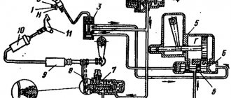
Pneumatic drive Kamaz
Pneumatic brake drive. The brake pneumatic drive has a source of compressed air - compressor 1. Compressor, pressure regulator 2, fuse 3 against freezing of condensate in compressed air and a condensation receiver
11 - supply part of the drive, from which purified compressed air under a given pressure is supplied to the remaining parts of the pneumatic drive and to other consumers of compressed air. The drive is divided into autonomous circuits separated by safety valves. Each circuit operates independently of the others.
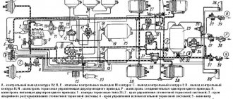
| Rice. 1 |
Fig.1. Pneumatic drive of the brake mechanisms of the KamAZ-5320 car
Circuit I of the drive of the front axle service brake mechanisms consists of a part of a triple safety valve 5, a receiver 14 with a volume of 20 liters with a condensate drain valve and a switch for the warning lamp for pressure drop in the receiver, a part of a two-pointer pressure gauge 20, a lower section of a two-section brake valve 16, and valve C of the control terminal , pressure limiting valve 18, two brake chambers 19, front axle brake mechanisms, pipelines and hoses between these devices.
In addition, the circuit includes a pipeline connecting the lower section of the brake valve 16 with the valve 26 for controlling the brake systems of a trailer with a two-wire drive.
Circuit II of the rear bogie service brake mechanism drive consists of a part of a triple safety valve, two receivers 12 with a total volume of 40 liters with condensate drain valves 15 and a switch for the warning lamp for pressure drop in the receiver, a part of a two-pointer pressure gauge 20, the upper section of a two-section brake valve 16, valve D control output, automatic brake force regulator 25 with an elastic element, four brake chambers 21, brake mechanisms. The circuit also includes a pipeline connecting the upper section of the brake valve 16 with the valve 26 for controlling the trailer brake systems.
Circuit III of the drive mechanisms of the spare and parking brakes, as well as the combined drive of the brake systems of the trailer (semi-trailer) consists of a part of the double safety valve 4, two receivers 13 with a total volume of 40 liters with a condensate drain valve and a pressure drop warning lamp switch in the receiver, two valves E and B control terminals, parking brake control valve 9, accelerator valve 24, part of a two-line bypass valve 23, four spring energy accumulators 21, parking brake warning lamp switch 22, valve 26 for controlling trailer brake systems with a two-wire drive, single safety valve 27, valve 29 control of trailer brake systems with a single-wire drive, three disconnect valves 28, three connecting heads (one head 32 type A for single-wire drive of trailer brake systems and two heads 31 type “Palm” for two-wire drive of trailer brake systems), pneumoelectric switch 30 of the brake signal, pipelines and hoses between these devices.
Circuit IV of the drive of the auxiliary brake mechanisms and other consumers consists of a part of the double safety valve 4, a pneumatic valve 8, two cylinders 7 for driving the dampers, a pneumatic cylinder 6 for driving the engine stop lever, a pneumatic electric switch 17 for the trailer solenoid valve, pipelines and hoses between these devices. Circuit IV does not have its own receiver or pressure drop indicator lamp. From circuit IV of the drive of the auxiliary brake mechanisms, compressed air is supplied to additional consumers via a pneumatic signal, a pneumatic clutch booster, drives of transmission units, etc.
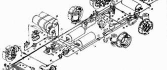
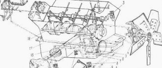
| Rice. 2 |
Kamaz-53212 pneumatic drive diagram
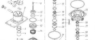
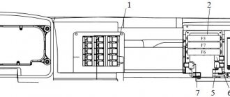
Moisture-oil separator
| Rice. 3 |
When describing the components and operating principle, the pneumatic drive of the KamAZ-5320 vehicle is taken as the basis. However, you should be aware that the brake actuators of other cars have their own distinctive features. To improve moisture separation in the supply part of the brake drive of the KamAZ-53212 vehicle in the compressor - pressure regulator section, a moisture separator is additionally installed on the first cross member of the frame in the zone of intense airflow. The KamAZ-5511 dump truck does not have trailer brake system control equipment, disconnect valves, or connecting heads.
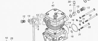
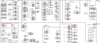
| Rice. 4 |
In addition, for KamAZ-5410, -5511 and 54112 vehicles, the block of protective valves consists of a triple protective valve, through which circuits I and II are filled with compressed air, and a single protective valve, through which circuit III is filled, and circuit IV is filled from circuit I or II.
autoruk.ru
Maintenance of the KamAZ brake system
During daily maintenance of the Kamaz brake system, it is necessary to:
- conduct an external inspection of the brake system;
- check for faults using an electronic device and eliminate them;
- drain condensate from receivers;
- Check the operation of the brake system in all positions.
Recommendations for subsequent maintenance are presented on the official Kamaz website.
Maintenance and performance testing of the pneumatic drive
Checking this system consists of measuring, checking and adjusting the air pressure parameters when leaving the device. The check is usually carried out for each valve individually. Before checking, you need to make sure that when you press the brake, there is no excessive release of air.
Check scheme:
- completely fill the system with air to the maximum pressure value;
- press the brake pedal fully, the pressure should not fall below 49.5 kPa;
- The drive handle must be in the front standard position; the pressure level must be checked.
What is needed to diagnose a pneumatic drive
In order to diagnose a pneumatic drive with your own hands, you need to use a special set of instruments.
The device is intended for:
- carrying out diagnostics of hoses to control pressure in the apparatus;
- replacing the pressure gauge during testing.
- Based on the test results, you must check the control table.
DIY brake system repair
Let's consider car breakdowns in which you can independently repair the brake chamber:
- increased free play of the brake pedal;
- the pedal is hard to press;
- the engine problem light flashes on the dashboard;
- the brake is not fully applied;
- ABS generates errors;
- the machine is not balanced when driving;
- strong vibration is felt when braking;
- brakes overheat quickly;
- discs wear out too quickly;
- The wheels do not brake evenly.
Detailed instructions for troubleshooting these problems yourself are presented on the official Kamaz website.
How to change
Before starting the procedure, it is recommended to release the parking brake and secure the rear wheels with shoes on both sides. After this, loosen the tension on the mounting bolts and nuts, jack up the tire treads and install the support stand.
In order to change the freewheels, you need to completely unscrew the wheel mounting mechanisms and remove all the bolts from the disk. Then you need to pull out the brake hose and use a screwdriver to bend the edges of the lock washers that secure the guide bolts from unscrewing. A screwdriver should be inserted between the disc and the brake bar on the side of the piston part of the caliper, press on the bar (this will help relieve the pressure of the pistons) and move the ratchet away from the disc. You can then lift the protective cover and remove the ratchet.
After these steps, you need to loosen the fastening nut and move the caliper housing along with the fixing brackets.
Before installing a new part, it is necessary to press the caliper piston inward until it stops using a pry bar. After this, it is recommended to check the brake fluid level in the system; if necessary, top up to the required level. You should also conduct an external inspection of the thickness of the disc and brake hose for damage and defects. If cracks are found, the elements must be replaced with new ones.
After this, you can install new ratchets. The mechanism is assembled by performing all steps in reverse order.
Adjustment of KAMAZ Euro-1,2,3 or 4 brakes is possible, full or partial. It is always necessary to check that the bearings on the wheel hubs are tightened correctly. It is necessary that the brake drums are not warm or hot. The parking brake needs to be released.
Full adjustment of KAMAZ brakes is carried out only when their disassembly and repairs have been completed, or in a situation where the alignment of the friction linings is disturbed.
Extending brake life with boring
In order to extend the service life of brake pads, they need to be rebored. This method is often used for Kamaz vehicles of the 65115 series. For this, a professional machine with an abrasive tip is used. A hole is made in the old brake pad and the tip is attached there. Then the car drives with such a block for some time. This method is quite simple, anyone can use it at home.
Air system of KAMAZ 5511 | KAMAZ
KAMAZ brake system
Pneumatic braking system
How to remove the main brake valve on a Kamaz 5511 car
Air leak from the brake valve KAMAZ ZIL PAZ MAZ KRAZ GAZ
Brake systems KamAZ
Why KamAZ slowly puts on the handbrake
KAMAZ handbrake brake valve
We install the KAMAZ accelerator on Foton 1093
Adjusting Kamaz brakes
I'm assembling a Kamaz for myself. Front brakes. (way out)
Also see:
- KAMAZ through puddles video
- About long KAMAZ trucks
- KAMAZ tachometer connection diagram
- KAMAZ cars video for boys
- KAMAZ does not maintain temperature
- KAMAZ new video
- Clutch housing KAMAZ 4308
- Poor braking KAMAZ
- How many tons can a KAMAZ dump truck hold?
- Tire pressure KAMAZ 5320
- Side windshields KAMAZ
- KAMAZ 65115 does not turn the starter
- KAMAZ trucks of the world video
- Driving KAMAZ vehicles
- Tightening torque of KAMAZ 5320 heads
Home » New » Air system of KAMAZ 5511 kamaz136.ru
To increase the reliability and reliability of the brake system, carry out a forced inspection and sorting of the brake devices once every two years, regardless of their technical condition.
The following are subject to forced rejection: pressure regulator; brake force regulators; brake chambers type 20/20; brake chamber type 24 (membrane); double safety valve; 4-circuit safety valve; manual brake valve; two-section brake valve; pressure limit valve; accelerator valve; trailer brake control valve (one- and two-wire drive); pneumatic valve.
Faulty devices that were forcibly removed or detected during a control check must be repaired using repair kits and checked for operability and compliance with specifications.
The procedure for assembling and testing the devices is set out in special instructions. Their repairs are carried out by persons who have undergone the necessary training.
Carry out a full adjustment of the brake mechanism after replacing the brake linings in the following order (* Before adjusting, check the tightness of the wheel hub bearings. The brake drums must be cold.):
- turn off the parking brake system;
- loosen the nuts securing the pad axles and bring the eccentrics closer together, turning the axles with the marks facing each other. The marks are placed on the outer ends of the axles;
- supply compressed air to the brake chamber at a pressure of 49... 68.8 kPa (0.5... 0.7 kgf/cm2) (press the brake pedal if there is air in the system or use compressed air from the installation). If there is no compressed air, remove the brake chamber rod pin and, pressing the adjusting lever towards the stroke of the brake chamber rod when braking, press the shoes against the brake drum. By turning the eccentrics in one direction or the other, center the pads relative to the drum, ensuring they fit snugly against the drum. Check the fit of the pads to the drum with a feeler gauge through the windows in the brake shield located at a distance of 20... 30 mm from the outer ends of the linings.
The 0.1 mm thick feeler gauge should not extend across the entire width of the pad;
- without stopping the supply of compressed air to the brake chamber, and in the absence of compressed air, without releasing the adjustment lever and holding the axes of the pads at rotation speed, securely tighten the axle nuts;
- stop supplying compressed air, and if there is no compressed air, release the adjusting lever and attach the brake chamber rod;
- Turn the worm axes of the adjusting lever so that the stroke of the brake chamber rod is 20... 30 mm.
Make sure that when turning the air supply on and off, the brake chamber rods move quickly, without jamming;
- check the rotation of the reels. They should rotate freely and evenly without touching the pads. After the indicated adjustment, there may be the following gaps between the brake drum and the pads: at the expansion knuckle 0.4 mm, at the axles of the pads 0.2 mm.
When installing the brake force regulator after replacing the intermediate and rear axles, pay attention to the fact that regulator 2 (see Fig. 304) and rod 4 connecting the regulator lever to the elastic element are installed vertically, elastic element 5 must be in a horizontal position ( neutral). The length of lever 3 must correspond to the value indicated in the table. 45.
Having established the required length of the lever, tighten the bolt securing the lever to the regulator. After installation, check the brake force regulator output pressure. To do this, fill the pneumatic system with compressed air to a control pressure of 637.5 kPa (6.5 kgf/cm2). With the pedal fully depressed, the pressure in the control terminal valve E (see Fig. 287) should be 215.8... 245.2 kPa (2.2... 2.5 kgf/cm2) (for an empty car). If the pressure in outlet valve E differs from that specified, then bring it into line by changing the length of the vertical rod 4 (see Fig. 304), moving it in the rubber coupling. Check the stability of the pressure generated by the brake force regulator by pressing the brake pedal repeatedly, then tighten the clamp on the connecting coupling.
By raising the tip of the elastic element by the amount of static deflection of the suspension indicated in Table 45, make sure that the pressure in the brake chambers of the rear bogie is equal to the control pressure, i.e. 588.4 kPa (6 kgf/cm2); if this does not happen, adjust the lengths of lever 3 and rod 4. Remember that rod 4 must enter the regulator coupling to a depth of at least 45 mm. Finally secure all connections.
When removing a brake chamber with a spring energy accumulator:
- set the hand brake valve to the “parking brake” position;
- unscrew the bolt for mechanical release of the spring energy accumulator until it stops, making sure that the brake chamber rod is retracted;
- disconnect the conductive pipelines, loosen the brake chamber, disconnect the rod fork from the adjusting lever;
- remove the brake chamber.