The fuel system of the car Ural 4320 Yamz 236 is not a diagram
BRIEF DESCRIPTION OF THE DEVICE AND OPERATION OF THE COMPONENT PARTS OF THE CAR, THEIR ADJUSTMENT AND MAINTENANCE
The car is equipped with an engine from the Yaroslavl Motor Plant (YaMZ). A description of the engine design, as well as instructions for operation and maintenance are given in the YaMZ engine operating instructions supplied with the vehicle.
Engine power supply system YaMZ-236NE2-3 for Ural-5557-40 vehicles
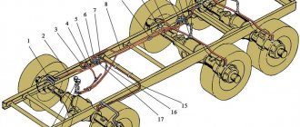
Engine fuel supply system. Fuel from the fuel tank 12 (Fig. 21) is sucked in by the fuel priming pump 6 and through coarse 8 and fine 19 filters it is supplied to the high pressure fuel pump (HPF) 17. The pump supplies fuel through tubes to the injectors, which inject fuel into the engine cylinders in accordance with with the order of their work. Excess fuel, and along with it the air that has entered the system, is discharged through the fine filter nozzle valve through fuel lines 1 and 5 into the fuel tank. Fuel that has leaked through the precision parts of the injectors through fuel lines 15 and 13 is also discharged into the fuel tank. The amount of fuel in the fuel tank is measured by an electrical level sensor installed in the tank and controlled by a gauge on the instrument panel.
Rice. 21. Diagram of the power supply system: 1,5,13,15,20—fuel drain lines; 2,4,7,10,18 - fuel supply lines; 3 — pre-heater fuel tank; 6 — low pressure fuel priming pump; 8 — coarse fuel filter; 9 — manual fuel priming pump; 11—fuel intake; 12 — fuel tank; 14 - tee; 16 — nozzle; 17 — high pressure fuel pump; 19 — fine fuel filter; a - fuel supply; b - fuel drain
SPARE PARTS AND ASSEMBLY PARTS
SPECIAL EQUIPMENT BASED ON URAL, MAZ, KAMAZ ____________________
Spare parts for Ural, Kraz, MAZ, Kamaz trucks. Engine parts YaMZ-236, YaMZ-238
Working systems of the car engine Ural-4320, Ural-5557
Power supply system (fuel system) of the Ural-4320, 5557 (YaMZ-236) engine
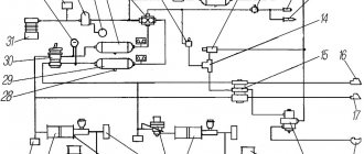
Fuel from the main fuel tank 1 (Fig. 1) is sucked in by the fuel priming pump 8 and through the coarse 22 and fine 13 filters it is supplied to the high-pressure fuel pump (HPF) 10.
Rice. 1. Diagram of the fuel system of the YaMZ-236NE2 engine of the Ural-4320, 5557
1-main fuel tank; 2,6,14,15,17,19,23 - fuel drain lines; 3-hose for draining fuel; 4-fuel drain valve; 5-tank additional fuel; 7-manual fuel priming pump; 8-low pressure fuel priming pump; 9-nozzle; 10-high pressure fuel pump; 11,12,21,24 - low pressure fuel lines; 13-fine fuel filter; 16-fuel tank pre-heater; 18-high pressure fuel lines; 20-speed controller; 22-coarse fuel filter; 25-fuel intake; a-fuel supply; b-fuel drain
The pump supplies fuel through tubes to the injectors, which inject fuel into the cylinders of the Ural-4320, 5557 engine in accordance with their operating order.
Excess fuel, and along with it the air that has entered the system, is discharged through the fine filter nozzle valve through fuel lines 15 and 17 into the fuel tank.
The fuel that has leaked through the precision parts of the injectors through pipelines 6 and 23 is also discharged into the fuel tank.
The amount of fuel in the main fuel tank is measured by an electrical level sensor installed in the tank and monitored by a gauge on the instrument panel.
Fuel supply control drive of the YaMZ-236NE2 engine of the Ural-4320, 5557 vehicle
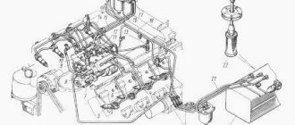
The fuel supply control drive of the Ural-4320, 5557 engine is mechanical and consists of a pedal, rods, levers, as well as a mechanism for manual fuel supply and engine stop.
When the pedal is in a free position, the control lever should rest against the bolt for limiting the minimum rotation speed on the injection pump regulator; this is ensured by adjusting the length of rod 2 (Fig. 2).
Rice. 2. Fuel supply control drive of the YaMZ-236 HE2 engine of the Ural-4320, 5557
1-fuel control shaft lever; 2-thrust; 3-fuel control lever; 4-cable strand clamp; 5-lever manual drive; 6-rod manual control; 7-traction handle; 8-pedal; 9-seal; 10-bolt adjustment; I-pedal position when the engine is running at minimum idle speed; II - pedal position when the engine is running at maximum speed and maximum power; a, b-gaps
Electrical diagram
p, blockquote 6,0,0,0,0 —>
| 1 | Front lamp |
| 2 | Side turn signal repeater |
| 3 | Low beam headlight |
| 4 | Connection panel |
| 5 | Horn relay |
| 6 | Torch candle EFU |
| 7 | High pitch electric signal |
| 8 | Fuse |
| 9 | Pre-heater motor |
| 10 | Coolant temperature gauge sensor |
| 11 | Low tone electrical signal |
| 12 | Spark plug for pre-heater |
| 13 | High voltage source |
| 14 | Pre-heater motor switch |
| 15 | Heater Plug Switch |
| 16 | Generator |
| 17 | Voltage regulator |
| 18 | Electromagnetic valve EFU |
| 19 | Condenser filter |
| 20 | Flare relay |
| 21 | Engine compartment lamp |
| 22 | Voltage Regulator Trip Relay |
| 23 | Additional resistor with electrothermal relay |
| 24 | Signal switch |
| 25 | Emergency oil pressure drop sensor |
| 26 | Oil pressure sensor |
| 27 | Oil filter contamination sensor |
| 28 | Emergency coolant overheat sensor |
| 29 | Pre-heater solenoid valve |
| 30 | Solenoid valve, fan clutch |
| 31 | Battery Switch Interlock Relay |
| 32 | Fan Clutch Relay |
| 33 | Fuel heater, preheater |
| 34 | Pre-heater solenoid valve switch |
| 35 | Fuel heating switch |
| 36 | Fan Clutch Switch |
| 37 | Thermo relay |
| 38 | Starter |
| 39 | Lower fuse box |
| 40 | Upper fuse box |
| 41 | Cab heater switch. |
| 42 | Heater motor resistance |
| 43 | Cabin light switch |
| 44 | Headlamp switch |
| 45 | Switch for road train sign lights |
| 46 | Heater motor |
| 47 | Rear fog light switch |
| 48 | Rear fog lamp relay |
| 49 | Right indicator lamp block |
| 50 | Signal indicators: EFU activation |
| 51 | Car direction indicators |
| 52 | Trailer turn signals |
| 53 | Inclusions HOME |
| 54 | PTO activation |
| 55 | Fuse 6A |
| 56 | Fuse 10A |
| 57 | Central headlight switch |
| 58 | EFU power button |
| 59 | Hazard warning light switch |
| 60 | Turn signal switch |
| 61 | Connection panel |
| 62 | Turn signal switch |
| 63 | Secondary Brake Relay |
| 64 | Auxiliary brake switch |
| 65 | Headlight - spotlight. |
| 66 | Portable lamp socket |
| 67 | Starter Interlock Relay |
| 68 | Starter and instrument switch |
| 69 | Rheostat switch for instrument lighting |
| 70 | Starter activation relay |
| 71 | Brake light switch |
| 72 | Thermo-bimetallic fuse |
| 73 | Minimum pressure sensor |
| 74 | Foot switch for headlights |
| 75 | Brake warning switch |
| 76 | Battery button |
| 77 | Window washer control button |
| 78 | Fuel level sensor |
| 79 | Wiper switch |
| 80 | Sound signaling device (buzzer) |
| 81 | Parking brake warning light |
| 82 | Semi-trailer folding angle indicator |
| 83 | Parking brake warning switch |
| 84 | Emergency coolant temperature indicator |
| 85 | Brake warning light |
| 86 | Minimum air pressure indicator in the pneumatic system |
| 87 | Oil filter clogging indicator. |
| 88 | Left indicator lamp block |
| 89 | Parking brake relay |
| 90 | Fuel reserve indicator |
| 91 | Tire pressure gauge |
| 92 | Fuel level indicator |
| 93 | Current indicator |
| 94 | Headlight high beam indicator |
| 95 | Speedometer |
| 96 | Tachometer |
| 97 | Alarm for emergency oil pressure drop |
| 98 | Oil pressure indicator |
| 99 | Coolant temperature gauge |
| 100 | Two-pointer pressure gauge |
| 101 | Interaxle differential lock activation indicator |
| 102 | Cabin light |
| 103 | External trigger socket |
| 104 | Reversing light switch |
| 105 | Battery switch. |
| 106 | PTO activation sensor |
| 107 | Switch on sensor HOME |
| 108 | Road train sign lantern |
| 109 | Rechargeable batteries |
| 110 | Windshield washer motor |
| 111 | Wiper motor |
| 112 | Rear fog lamp |
| 113 | Back lamp |
| 114 | Body signal switch |
| 115 | Reversing light |
| 116 | License plate light |
| 117 | Trailer socket |
| 118 | Cross-axle differential lock activation sensor |
| 119 | Underbody light |
Fuse box
It is located in the instrument panel, behind the protective cover. On the cover of each block the current strength for which the fuses located under it is designed is indicated.
p, blockquote 12,0,0,0,0 —>
- fog light chain
- headlight lamp circuit
- circuit of portable and engine compartment lamps, power circuit of control lamp units
- circuit of the cabin lamp, road train sign lights and brake light lamps
- heater motor and reversing light circuit
- power supply circuit for devices and buzzer
p, blockquote 13,0,0,0,0 —>
- left side light
- right side marker and instrument lighting
- low beam left headlight
- low beam right headlight
- left high beam headlight
- high beam right headlight
The remaining individual fuses are located under the hood (see diagram). For example, the heater power circuit is protected from short circuits by a 30 A bimetallic fuse 291.3722.
Description of modernized models
In later models, the fuse box itself is located in the same place, but made in a different form.
In some modernized Ural models, the fuse and relay box may be located in the panel on the right side, on the passenger side, behind a protective cover on which the current diagram will be printed.
Every time you check the high pressure pump you need to:
- Make sure the discharge valves are intact.
- Check the pressure in the pump supply cavity. If necessary, adjust the tightening of the bypass valve.
- Check and, if necessary, adjust the start of fuel supply by sections of the high pressure pump.
- Monitor and regulate the beginning of the rack ejection when the control lever is in full contact with the maximum speed bolt.
- Adjust the displacement of the rotary bushings relative to the gear sector within 105-107 mm3 per cycle (105-107 cm3 per 1000 plunger strokes).
- Using the regulator bracket, check that the fuel supply is turned off.
If faulty spare parts for the engine are found, we recommend replacing them immediately. You can purchase spare parts for the power supply system of Ural vehicles on our website.
YaMZ engine cooling system
The YaMZ engine cooling system (Fig. 63) is liquid, closed type, with forced circulation of coolant, and is also a heat source for heating the cabin and blowing warm air onto the windshields. A preheater is connected to the cooling system.
The cooling system includes: radiator I with fan casing 24, fan 9, expansion tank 3, radiator shutter 15, hoses and pipelines, water pump and thermostats.
Rice. 63. Engine cooling system: 1 — water radiator; 2 - hose; 3 - expansion tank; 4 — curtain drive cable; 5 — guide tube; 6 - chain; 7 — thermostat box; 8 — connecting hose; 9 - fan; 10 — upper pipe; 11 — curtain drum beam; 12 - seal; 13 — upper cross member; 14 — guide rod; 15 — curtain with drum assembly; 16; 18 — hoses of inlet and outlet pipes; 17 — oil cooler; 19 — emphasis; 20 — curtain fabric; 21 — steam outlet tube; 22 - bracket; 23 - nut; 24 — fan casing; 25 — lower pipe hose; 26 — distribution pipe; 27 - thrust; 28 — hose
The engine coolant temperature is regulated by automatic thermostats 7 and manually by shutter 15 by changing the amount of air passing through radiator 1.
The shutter control drive is brought into the cabin and is carried out using a cable 4 and a chain 6. When the chain is extended to the fullest extent, the radiator is closed with a cloth 20. The shutter can be fixed in various positions by installing a chain link in the slot of the guide tube 5-. When the drum is lowered, cable 4 of the curtain drive must be tensioned and secured.
The radiator is a four-row, tubular-belt type, consisting of upper and lower tanks connected by a frame (the radiator of the KrAZ-260 car has a filler neck, hermetically sealed with a plug).
The expansion tank is designed to prevent the release of coolant from the radiator and improve the thermal conditions of the engine. Tank 3 is connected to the water radiator by hose 2, and to the water distribution pipe by hose 28.
The expansion tank shaft plug has inlet (air) and outlet (steam) valves. A steam-heating tube 21 is attached to the filler neck of the tank, which connects the cooling system to the atmosphere during the operation of one or more valves of the expansion tank plug.
The radiator shutter is installed in front of the water radiator and is designed to ensure normal engine thermal conditions even at low temperatures.
The curtain 15 consists of a drum with a fabric 20 wound on it, the lower end of which is fixedly fixed to the frame through the plate. There is a spring installed inside the drum. Springs are installed on both sides of the drum, which cover the guide rods and move along them when the curtain is raised and lowered.
The water pump is a vane, centrifugal type. To prevent liquid from entering the cavity with lubricant, install a cuff 8 (Fig. 64) made of oil- and petrol-resistant rubber, which is pressed with clips against the shaft, and with a spring against the textolite thrust ring 6.
The fan is designed to create an intense air flow between the radiator tubes, which cools the liquid that flows into the lower reservoir. An axial-type fan with a six-blade stamped-riveted impeller, together with the drive, is installed and attached to the front end of the distribution cover.
The fan is driven from the distribution gear, with which the fan gear is meshed.
Thermostats are designed to maintain a constant temperature of the coolant in the cooling system while the engine is running. The system has two thermostats type TS 107-06 with solid filler, one for each row of cylinders.
List of possible cooling system malfunctions
| Increased consumption (leakage) of coolant Reduced fluid temperature in the cooling system, slow engine warm-up Increased temperature of the liquid in the cooling system* | Fluid leakage at the junction of hoses with pipes and radiator tubes Fluid leakage through the drain valves Fluid leakage from the drain hole on the water pump body Violation of the tightness of the expansion tank plug Violation of the tightness of the walls of the expansion tank Malfunction of thermostats (valves are constantly open) The radiator curtain does not close Damage to the curtain fabric The radiator curtain is closed Thermostat valve sticking in closed ohm position Insufficient tension or breakage of the water pump drive belt Contamination of the external surfaces of the radiator Contamination of the internal surfaces of the cooling system or deposition of scale or corrosion products on them Insufficient amount of fluid in the cooling system Ineffective fan operation (bent blades or their breakage) Presence of gases in the engine water jacket due to contamination cylinder head gaskets (a sign of water being released through the steam pipe when the radiator cap is closed) | Tighten the hose clamps, and if the hoses are damaged, replace them. Tighten the faucets or replace them. Replace the thrust ring and cuff of the water pump impeller. Replace the plug gasket or replace the plug. Apply patches. Replace thermostats (see faults in this “List” below in the text). Replace the blade. Open the shutter. Replace the thermostat. Adjust the belt tension. or replace it Blow out the radiator with compressed air or flush it Rinse the system with clean water. If scale deposits occur, flush the system with a special solution. Add liquid to the cooling system to the required level. Straighten the fan blades or replace the fan. Replace damaged cylinder head gasket |
| The radiator shutter does not close | Damage or wear to the parts of the shutter control drive; Broken curtain drum spring; Bent guide rods (along which the darning moves) | Replace damaged or worn parts Replace the spring Straighten the guide rods |
*Before looking for the cause of the malfunction, you must make sure that there is a sufficient amount of coolant in the system.
www.avtotatcenter.ru
Relay block
The main relays are mounted on the front panel under the hood of the Ural.
There may be: horn relay, fan relay, starter relay, turn switches, parking brake relay, etc.
p, blockquote 21,0,0,0,0 —> p, blockquote 22,0,0,0,1 —>
That's all. And if you want to help supplement the material, write in the comments.
Source
Subsequent adjustment should be performed according to the following algorithm:
- Bring the governor control lever into contact with the minimum idle speed bolt. At 450-500 rpm, use the rocker screw to set the rack's power reserve, which is 0.5-11 mm after the feed is completely turned off.
- Bring the control lever to full contact with the maximum speed bolt, using this bolt to set the start of the rack ejection at a pump camshaft speed of 1100 per minute.
- Bring the governor control lever all the way to the maximum speed bolt. At 1030 rpm of the camshaft, position the rack so that it is in a position different from the extreme extended position by 13 ± 0.2 mm; To make such an adjustment, you need to rotate the nominal feed adjusting bolt, which is located on the regulator lever.
- Bring the governor control lever all the way to the maximum speed bolt. At 1030 + 10 camshaft revolutions per minute, supply fuel to each pump section within the range of 113-115 mm3/cycle (113-115 cm3 per 1000 plunger strokes or 116-118 cm3/min).
- Find out what the feed rate is at 80±10 camshaft revolutions per minute. It should fit within the range of 220-240 mm3/cycle (220-240 cm3 per 1000 plunger strokes). You can adjust these indicators using a screw, but only in the direction of increasing them. After adjustment, the rocker screw must be secured by hammering, while the protrusion of the rocker bracket, which limits its movement, should not come into contact with the screw securing the regulator cover.
- In order to adjust the start flow, you need to use the nominal flow adjustment bolt, which is located on the regulator lever, with the control lever resting on the maximum mode bolt and the number of revolutions of the cam shaft of the pump is 1030+10 per minute, again set the flow rate to the pump sections in the range 113-115 mm3/cycle
- Turn the control lever all the way to the maximum speed limitation bolt, using this bolt to set the start of the rack ejection at a pump camshaft speed of 1070 per minute.
- In the same position of the control lever, specify the number of revolutions of the pump camshaft, which should correspond to complete shutdown of the supply to the pump sections. It should start at 1120-1150 camshaft revolutions per minute.
- Close the regulator with the inspection hatch valve, and use the fuel supply limiter screw to set the flow rate of the pump sections at the number of camshaft revolutions per minute within the limits of 105 mm3/cycle (105 cm3 per 1000 plunger strokes). Then you need to secure the limiter screw with a nut. In this case, the lever should rest against the maximum speed bolt.
- Turn the control lever until it comes into full contact with the minimum idle speed bolt. Then we monitor and, if necessary, adjust the number of revolutions of the full automatic shutdown of the fuel supply (the number of camshaft revolutions should be within 250 per minute).
- Using the regulator bracket, we check that the supply is turned off. By turning the bracket down 45°, the fuel supply from all sections of the pump should stop.
- Secure the automatic injection advance clutch by tightening the nut of its fastening with a torque of 10-12 kgm. The tightening of the coupling nut must be checked whenever the high-pressure pump is removed from the engine.
When the clamping screw of a particular gear sector is loosened, the feed rate of the section decreases when the sleeve is turned to the left, and increases when turned to the right. After adjustment, you need to tighten all the tightening screws tightly.
The number of revolutions of complete shutdown of the feed can be adjusted by changing the location of the adjusting screw of the double-arm lever. Afterwards, you need to set the maximum speed limit bolt again to start the ejection of the rack (the number of cam shaft revolutions is 1070 per minute) and check the number of revolutions of complete shutdown.
By screwing in the screw of the double-arm lever and restoring the start of ejection of the rack, the number of revolutions is reduced to completely turn off the feed, and when unscrewed, it is increased.