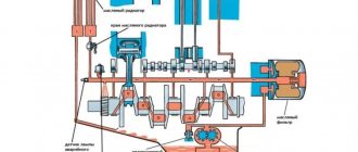
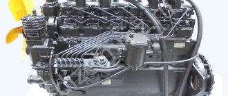
The D-240 engine of the MTZ-80 tractor uses a combined single-circuit lubrication system. Pump 2 (Fig. 1) sucks oil through oil intake 1 and pumps it into full-flow active-reactive (nozzleless) centrifuge 4. Then the oil through radiator 5 or bypassing it enters the crankcase line to the crankshaft main bearings and camshaft bearings. It is fed from the main bearings through drillings in the cheeks to the connecting rods. From the camshaft journal, oil flows in a pulsating flow into the internal cavity of the rocker arm axis, and through the holes in it to the rocker arm bushings. Through the channels in the rocker arms, oil flows to the spherical surfaces of the pusher rods.
Fig.1. Interaction of lubrication system devices D-240 1 – oil intake; 2 – pump; 3 – safety valve; 4 – centifuge; 5 – radiator; 6 – pressure gauge indicator; 7 – drain valve; 8 – radiator thermostat valve; K and Sh – main and connecting rod bearings; P – camshaft supports; PN and PSh – fuel pump drive gears and intermediate: VK – rocker arm bushings
Cylinder liners, pistons, pushers, camshaft cams, gear teeth and other parts of the D-240 engine of the MTZ-80 tractor are lubricated with oil flowing from the bearing clearances.
The oil pump (Fig. below) is a single-stage, gear type, installed on the cover of the first main bearing of the crankshaft and driven by the diesel crankshaft. The main parts of the pump: body 2, cover 5, drive gear 6 and drive gear 9, mounted on the shaft, and driven gear 4, located on pin 3.
When gears 9 and 4 rotate, a vacuum is created in the suction zone, due to which oil flows through the oil intake into the pump. Getting between the gear teeth, the oil is pumped into the line, and from it is supplied to the rubbing parts.
The depth of the borings for the gears in the housing, the width of the gears and their location are carried out with great precision. To seal the internal cavity of the oil pump, the mating planes of the housing and cover are ground. To create bearing alignment, the cover is connected to the housing using two control pins, the holes for which are machined together. Therefore, moving the cover from one pump to another is unacceptable. The pump flow is 36 l/min at a rotation speed of 2320 rpm and the pressure developed by the pump is 0.70…0.75 MPa (7.0…7.5 kgf/cm2).
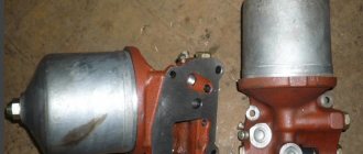
The oil filter (Fig. below) is designed to clean the oil circulating in the lubrication system. The diesel engine is equipped with a centrifugal filter with a nozzleless hydraulic drive.
An axis 15 is screwed into the centrifuge body 79, on which a rotor rotates, consisting of a frame 8, an inner cup 77, a bottom cover 12 and a top cover 13. The cover 12 is attached to the frame 8 with a nut and sealed with a rubber ring 14. Washer 2 and nut 4 installed on the upper threaded end of the axis 15, limit the axial movement of the rotor. The rotor is closed on top with a cap 7, which is secured with a nut 3 and washer 2. An oil drain pipe runs inside the axle.
From the oil pump, oil flows through a channel in the cylinder block, and then through an annular channel and holes in the rotor axis into the nozzle 10, which is secured to the axis with a pin. Through the slots in the nozzle, the oil is supplied in a tangential direction, acquires a rotational movement, and through the holes in the rotor frame enters the inner cup 77. The reflective shoulder of the rotor cover directs the oil upward. Under the influence of centrifugal forces, products of combustion and decomposition of oil and wear of parts are deposited on the inner walls of the rotor. The purified oil is thrown out at high speed through a tangential hole in the upper part into the internal groove of the rotor housing in the area of the radial outlet holes (7) of the rotor axis. This creates a reactive force that rotates the rotor. Then the oil flows through the holes in the rotor axis and the tube (9) into the main oil line.
Reducing (unregulated) valve
17 is used to bypass cold oil into the main line, bypassing the oil cooler. The valve spring force is less than the radiator resistance to the flow of cold oil, so if it is cold, the valve opens and oil flows into the line.
Oil radiator
designed to cool oil, the temperature of which can increase significantly during prolonged operation of a diesel engine at full load, especially at high ambient temperatures. Passing through numerous radiator tubes, the oil is cooled by the counter flow of air by 10-15°C and enters the diesel engine.
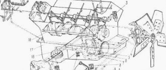
Accessories and components of the oil cooler of the D-240/243 engine of the MTZ-80 tractor
- 0 – 70-1405100 Oil pipe assembly
- 1 – 70-1405089 Fitting
- 2 – A40/50-4616339 Washer
- 3 – 70-1405120 Oil line
- 4 – XS-21-P29 Clamp
- 5 – 70-1405013 Hose
- 6 – 70-3407146 Plank
- 7 – 70-3506027 Bushing
- 8 – 70-3407144 Plank
- 9 – Bolt М8-6gх35.88.35.019 GOST 7796-70
- 10 – Washer 8N GOST 6402-70
- 11 – 70-1405109 Oil line
- 12 – Bolt М8-6gх45.88.35.019 GOST 7796-70
- 13 – Washer 8 GOST 11371-78
- 14 – Nut M8.6N.019 GOST 5915-70
- 15 – 70-1405117 Oil line
- 16 – 70-1405011 Tube
- 17 – 70-1405112 Clamp
- 18 – 70-1405230 Filter
- 19 – 70U-1405010 Radiator
- 20 – 70-1405110 Oil line
- 21 – 40-4607038-A Washer
- 22 – 40-4607032 Bolt
- 23 – 70-1405120 Oil line
Engine lubrication system D 240 - centrifuge, oil pump and maintenance
» Engine D-240 » Engine lubrication system D 240 – centrifuge, oil pump and maintenance
The D-240 engine has a combined lubrication system. Based on the operating conditions of the parts, oil flows to the rubbing surfaces (crankshaft crankpins and main journals, camshaft bearing journals, fuel pump gear bushings and intermediate gear) under pressure, but in a pulsating flow (valve mechanism) or by splashing. The engine lubrication system includes: a full-flow centrifugal oil filter (centrifuge), an oil pump with an oil receiver and an oil cooler. The lubrication system also includes connecting fittings, oil lines, safety valves, control devices and others. Some diesel components (starter, pump, fuel pump) have their own autonomous lubrication circuit. To lubricate the engine of the MTZ-82 tractor, motor oil is used: in winter - grade M8G2, in summer - M10G2. The oil must be changed every 480 hours of engine operation.
Lubrication system diagram: 1 - oil cooler; 2 - main oil line; 3 — oil pressure indicator; 4 - mesh; 5 - centrifuge; 6 - oil pump; 7 - pressure reducing valve; 8 - drain valve; 9 - safety valve; 10 — thrust rings; 11 - pipe; 12 — oil receiver; 13 - oil cooler.
Oil pump D-240
Single-stage, gear type, mounted on the first crankshaft main bearing cap and rotated from the engine crankshaft. The pump consists of a cover, a housing, drive and drive gears mounted on the shaft, as well as a driven gear located on the pin.
During the rotation of the gears, a vacuum is formed in the suction area, which facilitates the flow of oil into the oil intake of the pump. Getting into the gear teeth, the oil is supplied to the main line, and from there it goes to the rubbing units.
The depth of the borings for the gears in the housing, their width and placement are carried out with high precision. To create a tightness in the internal cavity of the oil pump, the mating planes of the cover and housing are carefully ground. It is not allowed to move the cover from one pump to another. The oil supply by the pump is 36 liters per minute at a speed of 2320 rpm and the generated pressure is 0.70-0.75 MPa (7.0-7.5 kgf/cm²).
Oil pump: 1 - oil intake; 2 - pump housing; 3 — driven gear pin; 4 — driven gear; 5 — housing cover; 6 — pump drive gear; 7 - pin; 8 — pump shaft; 9 - drive gear; 10 - pipe.
Oil filter
The D-240 engine centrifuge is designed to clean circulating oil in the lubrication system. A centrifugal filter equipped with a nozzleless hydraulic drive is installed on the engine.
The filter housing has an axis on which the rotor rotates. The cover is attached to the frame with a nut and sealed with a rubber ring. The rotor is held from axial movement by a washer and nut located at the upper end of the threaded axle. The rotor is closed from above with a cap secured with a nut and washer. An oil drain tube is located in the internal cavity of the axle. Under the influence of centrifugal forces, small particles, wear products of parts and oil decomposition remain on the inner walls of the rotor. The purified oil is thrown at high speed through a tangential hole into the internal bore of the rotor housing in the area of the inlet holes of the rotor axis. As a result, a reactive force is generated that rotates the rotor. Next, the oil is fed through the holes in the rotor axis and the tube into the main oil line.
The safety valve controls the pressure in front of the rotor to 0.65-0.70 MPa (6.5-7.0 kgf/cm²). If the oil pressure at the rotor inlet exceeds this value, it is drained through the valve into the sump.
The drain valve pressure is adjusted to a value of 0.20-0.30 MPa (2-3 kgf/cm²) and maintains the required pressure in the main oil line.
Centrifuge (oil filter): 1 — filter housing; 2 - tubes; 3 — rotor axis; 4 — rotor cover; 5 - glass; 6 — nozzles; 7 — rotor housing; 8 — rotor cup; 9 — thrust ring; 10 - special nut; 11 — washer; 12 - nut; 13 — filter cap; 14 - nut; 15 — cap gasket; 16 - sealing ring; 17 - safety valve; 18 — fitting for connecting a pressure gauge; 19 — oil line to the radiator; 20 - pressure reducing valve; 21 - drain valve; 22 - plug; 23 - adjusting plug.
A pressure reducing valve (unregulated) is necessary to transfer cold oil into the main line, bypassing the oil cooler.
The oil cooler is used to cool the engine oil, the temperature of which may increase during prolonged operation of the engine at maximum load, especially at high ambient temperatures. Passing through a large number of copper radiator tubes, the oil is cooled by the air flow from the fan by 10-15º C and supplied to the engine.
Maintenance of the D-240 engine lubrication system
Before each engine start, it is necessary to check the oil level in the crankcase. Only engine oil recommended by the manufacturer should be used in the engine. To fill the oil, use a special container equipped with a filter element. It is recommended to fill the oil no higher than the top mark. It is prohibited to start a diesel engine when the oil level is below the control mark on the dipstick. An increased oil level in the engine will lead to a significant splash of oil onto the cylinder mirrors, deterioration in the performance of the piston group and intense diesel smoke. If the oil content is low, the lubrication of parts deteriorates.
It is recommended to change the oil after every 480 hours of engine operation, as over time it loses its lubricating properties. Oil drains from the crankcase when the engine is warm. Before adding oil, you must clean the centrifuge rotor.
Maintenance of the D-240 engine lubrication system also involves regularly monitoring the oil pressure. The oil pressure at the nominal crankshaft speed should be 0.2-0.3 MPa (2.0-3.0 kgf/cm²), at minimum speed - not less than 0.8 MPa (0.8 kgf/cm²). Increased or decreased pressure indicates a malfunction in the lubrication system. A sharp drop in pressure can occur due to oil leakage from the oil lines, incorrect operation of the pressure gauge, safety or drain valve, and damage to the oil pump.
The centrifuge rotor must be cleaned every 480 hours of operation. To do this, you need to disassemble the oil filter and use a scraper to clean the rotor from any deposits that have formed. Before installing the rotor, lubricate the rubber sealing ring with oil.
04.10.2020
Operating principle of the lubricant complex
The operating principle is simple and effective at the same time - the pump sucks oil from the oil sump and pumps it into a centrifuge, from where it enters the crankcase line to the camshaft and crankshaft bearings and continues its path to the connecting rod bearings, moving from the camshaft journal to the rocker arm axis, and then and their bushings, after which, through special channels, it fills the spherical surfaces in the pusher rods.
The built-in safety valve is responsible for regulating the pressure, which at the inlet to the filter should not exceed 0.7 MPa. Due to the thermostat valve, cold oil bypasses the radiator and enters the main line, which speeds up the process of warming up not only the oil, but also the engine. The drain valve limits the operating pressure in the main line. General control of the oil pressure in the system is carried out using a pressure gauge.
Lubrication system of the MTZ-82 (MTZ-80) tractor
The engine of the MTZ-82 (MTZ-80) tractor uses a combined lubrication system: one part of the parts is lubricated under pressure, the other by splashing oil. The engine cylinder block has a longitudinal oil channel, from which oil is supplied through transverse channels to each main bearing and to all camshaft bearing journals. The crankshaft and camshaft bearings, the intermediate gear bushing and the fuel pump drive gear, as well as the valve mechanism, are lubricated under pressure from the gear oil pump. Liners, pistons, piston pins, camshaft cams, and the pump drive are splash lubricated.
Rice. 20. Centrifugal oil filter: 1 - rotor axis; 2 — centrifugal filter housing; 3 - nozzles; 4 — locking screw; 5 - tube; 5 — rotor housing; 7 — inner glass; 8 — rotor housing cover; 9 — stacked rotor; 10 — special nut; 11 — sealing ring; 12 — thrust washer; 13 — nut; 14 — centrifugal filter cap; 15 - ring; 16 — cap nut; 17 — washer; 18 — safety valve; 19 — drain valve: 20 — radiator valve (reducing); 21 - screw; 22 — tangential holes; 23 - radial holes. General lubrication instructions Depending on the ambient temperature, use oils of different viscosities according to this manual. The physical and chemical properties of the oils used must correspond to those indicated in the table “Oils and lubricants used for Belarus tractors.” The oil level when filling the engine crankcase should be checked with an oil dipstick. In a fueled, idle engine, the oil level should be at the height of the top “P” (full) mark on the oil dipstick. After pouring oil into the crankcase, it is recommended to run the engine for 2-3 minutes to fill the system with oil. Then stop the engine, let the oil drain and check the oil level again; if necessary, add oil to about 0. It is not allowed to operate the engine with the oil level in the crankcase below the “O” mark on the oil measuring rod. Change the oil in the crankcase every 240 (for oils M8V and M10V) or 480 (for oils M8G and M10G) hours engine operation, for which: 1. Drain all oil from the engine crankcase immediately after stopping the engine.2. Clean the centrifugal filter rotor following the instructions below.3. Fill the crankcase with clean oil.4. After changing and washing the filter, check all external connections of the lubrication system with the engine running and, if a leak is detected, repair it. It is not allowed to extend the oil change period. During engine operation at the nominal speed, the oil pressure should be within 2-3 kgf/cm2. If the engine is started when it is not warmed up, the oil pressure may be higher - up to 6 kgf/cm2. At a minimum idle speed, it is allowed to reduce the oil pressure to 0.5 kgf/cm2 on a warm engine. If the oil pressure at the nominal speed is below 1 kgf/cm2, the engine must be stopped to determine and eliminate the causes of the drop in oil pressure. If the oil pressure is above or below the specified limits, first inspect the drain and safety valves of the centrifugal filter. If there are nicks on the surface of the valve, clean them and wash the seat and valve. If after this the oil pressure in the lubrication system remains low, increase the tightening of the drain valve spring 19 (Fig. 20). A decrease in engine oil pressure can also be due to an increase in clearances in the main and connecting rod bearings. Cleaning the centrifugal oil filter Clean the rotor of the centrifugal oil filter every 120 (when using M8V and M10V oils) or 240 hours of operation (when using M8G and M10G oils). When maintaining the centrifuge, the rotor assembly is not removed from the axis. Complete disassembly of the rotor is carried out only if it is necessary to replace parts. Clean the rotor in the following sequence: 1. Remove the cap 14 (Fig. 20) by unscrewing the cap nut 16.2. Place a screwdriver (wrench, small diameter rod, etc.) between the bottom of the rotor and the bowl of the centrifuge body 2 and stop the rotor from turning. Using a wrench 3 = 36 mm, unscrewing nut 10 securing the rotor shell, compress the rotor shell 9.3. Remove the layer of deposits from the inner walls of the rotor bowl using a wooden scraper.4. If necessary, clean the nozzle holes in the rotor housing.5. Reassemble the assembly in the reverse order. Before installing the rotor cup 9, lubricate the sealing ring 11 on the bottom of the rotor housing with diesel oil or grease. When installing the cup, make sure that the sealing ring does not fall out of the groove in the rotor housing and does not cut it off. Screw the cup fastening nut 10 with light force until the cup is completely seated on the rotor body. After assembling the rotor, check its rotation by hand. In this case, the rotor should rotate easily, without jerking, jamming or beating. Check the condition of the cap seal and install the centrifugal filter cap. Check the operation of the centrifugal filter as follows: after stopping the engine for 30-60 seconds, a slight noise from the rotation of the rotor should be heard under the centrifuge cap. If there is no noise, disassemble the rotor in the order indicated above, while paying attention to ensure that there are no nicks on the mounting surfaces of the centrifuge body and cap, which can lead to axis misalignment and jamming of the rotor. If no visible defects are found, it is necessary to completely disassemble the rotor, for which: 1. Unscrew nut 13, remove washer 12.2. Lift the rotor on the axle and use a wrench S=27 mm to remove the axle and rotor assembly from the centrifuge body.3. Unscrew three screws 21 and remove the axle assembly with the nozzle from the rotor housing.4. Clean and blow out the slotted holes in nozzle 3, check that the nozzle is securely locked. Reassemble the centrifuge in the reverse order. If the measures taken do not ensure normal operation of the centrifuge, remove it from the engine, check whether the valves are stuck and that they are adjusted correctly. Approximately adjust the centrifuge valves can be considered correct if the recess of the adjusting plugs of the safety and drain valves from the end of the body is 15-20 mm. Flushing the engine breather Wash the breather gasket with diesel fuel every 960 hours of engine operation. Untimely flushing can lead to contamination of the packing, which causes increased pressure in the crankcase and oil leakage through the seals in the engine. Sources used:
- https://studwood.ru/1648676/tehnika/sistema_smazki_dvigatelya
- https://tractor-mtz82.ru/dvigatel_d-240/sistema_smazki_dvigatelya_d_240_-_centrifuga_maslyanyj_nasos_i_obsluzhivanie.html
- https://traktor-mtz82.ru/dvigatel-traktora-mtz-82-80/23-sistema-smazki…