Types of Brake Valves
Trucks, including KamAZ, operate on a braking system that uses a pneumatic drive.
According to the type of design, there are two types of brake valves:
The second type of crane is usually installed on KamAZ trucks, since they are heavy-duty.
The two-section crane can also be of several types for different car models:
- Each brake section is controlled separately;
- unified control of all sections.
The design and operating principle of these types of brake valves are the same.
Typically, KAMAZ vehicles from version 5320 are equipped with a Wabco 100-3514008 brake valve.
KAMAZ brake system // Purpose
The service braking system is designed to reduce the speed of the vehicle or stop it completely. The brake mechanisms of the service brake system are installed on all six wheels of the vehicle. The drive of the service brake system is a dual-circuit pneumatic system; it operates separately the brake mechanisms of the front axle and the rear bogie of the vehicle. The drive is controlled by a foot pedal, mechanically connected to the brake valve. The executive bodies of the service brake system drive are the brake chambers [1, 2].
The spare brake system is designed to smoothly reduce the speed or stop a moving vehicle in the event of a complete or partial failure of the working system [1, 2].
The parking brake system ensures braking of a stationary vehicle on a horizontal section, as well as on a slope and in the absence of a driver.
The parking brake system on KamAZ vehicles is designed as a single unit with the spare one, and to activate it, the hand valve handle should be set to the extreme (upper) fixed position [1, 2].
The emergency brake release drive provides the possibility of resuming the movement of a vehicle (road train) when it is automatically braked due to a leak of compressed air, an alarm system and control devices that allow monitoring the operation of the pneumatic drive.
Thus, in KamAZ vehicles, the brake mechanisms of the rear bogie are common to the working, spare and parking brake systems, and the latter two also have a common pneumatic drive.
The brake auxiliary system of a vehicle serves to reduce the load and temperature of the brake mechanisms of the service brake system. The auxiliary braking system on KamAZ vehicles is an engine retarder, when activated, the engine exhaust pipes are blocked and the fuel supply is turned off [1, 2].
The emergency brake release system is designed to release spring energy accumulators when they are automatically activated and the vehicle stops due to a compressed air leak in the drive [1, 2].
The drive of the emergency brake release system is duplicated: in addition to the pneumatic drive, there are emergency release screws in each of the four spring energy accumulators, which allows the latter to be released mechanically.
The alarm and control system consists of two parts [1, 2]:
a) light and acoustic signaling about the operation of brake systems and their drives.
At various points of the pneumatic drive, pneumatic-electric sensors are built in, which, when any braking system, except for the auxiliary one, closes the circuits of the electric brake light lamps.
Pressure drop sensors are installed in the drive receivers and, if there is insufficient pressure in the latter, they close the circuits of the signal lamps located on the vehicle's instrument panel, as well as the sound signal (buzzer) circuit.
b) control valves, with the help of which the technical condition of the pneumatic brake drive is diagnosed, as well as (if necessary) the selection of compressed air.
ts-kamaz.narod.ru
Main brake valve KAMAZ EURO
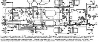
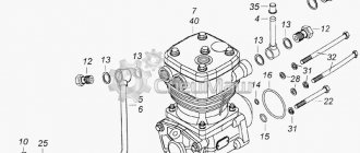
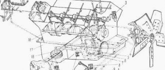
On modern trucks produced by the KamAZ company, the Euro standard State Customs Committee is installed. The structure of the main brake valve is shown in the figure below.
Construction of the KamAZ main brake valve
1 — top cover of the valve body; 2; 19 — screws securing the structure; 3;18 - washers for fastening on a spring basis; 4 — pushing device; 5 — GTK bushing; 6 — body base of the control lever; 7 — screw for adjusting the gas turbine engine; 8 — control lever; 9 — fastening nut; 10 — spring plate; 11 - device for maintaining balance; 12 — ring for seal; 13 — GTK piston; eleven; 16; 24; 28 — spring fastenings; 15 — hull base of the upper part of the GTK; 17;29 - support base; 20;32 — base rings; 21 - large diameter piston; 22 — atmospheric valve GTK; 23 - small diameter piston; 25 — body of the lower base; 26;30 - ring parts; 27 — body base of the valve of the lower part of the GTK; 31 — exhaust window of the GTK.
Design and principle of operation
The device includes the following elements:
- inlet and outlet type valve;
- spring mechanism and compressor;
- rubber bushing;
- air pressure regulator;
- piston part and diaphragm.
The operating principle of the brake valve of a KamAZ semi-trailer:
- Pressing the brake pedal causes the rod to move to the right, which closes the valve.
- At this time, the valve opens, activating the brake chamber and receiver. The pressure in the brake system will depend on the degree of pressure on the pedal.
- With constant force on the brake pedal, the pressure on the piston increases.
- The force is transmitted through the mechanism of handles and rods to the crane lever, passing through the pusher element and the rubber bushing.
- The movable intake valve seat moves downward along with the piston part.
- The inlet window closes, the exhaust valve window opens.
- Passing through the outlet and the open valve window, the air flow is directed to the valve cavity.
- The pressure in the upper cavity begins to increase. When the pressure level increases, the air flow moves to the area above the piston, activating the operation of the entire mechanism.
The two-section brake valve (see Fig. 300) is used to control the actuators of the dual-circuit drive of the service brake system of the KamAZ .
The brake valve is controlled by a pedal directly connected to the brake valve.
Rice. 300. KamAZ brake valve with pedal drive: 1 - pedal; 2 — adjusting bolt; 3 — protective cover; 4 — roller axis; 5 - roller; 6 — pusher; 7 - base plate; 8 - nut; 9 - plate; 10, 16, 19, 27 - sealing rings; 11 — hairpin; 12 — follower piston spring; 13, 24 - valve springs; 14, 20 — valve spring plates; 15 — small piston; 17 — valve of the lower section; 18 - small piston pusher; 21 - atmospheric valve; 22 - thrust ring; 23 — atmospheric valve body; 25 - lower body; 26 — small piston spring; 28 - large piston; 29 — valve of the upper section; 30 - follower piston; 31 - elastic element; 32 — upper body; A - hole; B - cavity above the large piston; I, II - input from the receiver; III, IV - output to the brake chambers of the rear and front wheels, respectively
The brake valve has two independent sections arranged in series. Inputs I and II of the valve are connected to the receivers of two separate drive circuits of the service brake system. From terminals III and IV, compressed air flows to the brake chambers. When you press the brake pedal, the force is transmitted through the pusher 6, plate 9 and elastic element 31 to the follower piston 30. Moving down, the follower piston 30 first closes the outlet hole of the valve 29 of the upper section of the brake valve, and then lifts the valve 29 from the seat in the upper housing 32, opening the passage of compressed air through input II and output III and further to the actuators of one of the circuits. The pressure at terminal III increases until the force pressed on pedal 1 is balanced by the force created by this pressure on piston 30. This is how the tracking action is carried out in the upper section of the brake valve. Simultaneously with the increase in pressure at port III, compressed air through hole A enters cavity B above the large piston 28 of the lower section of the brake valve. Moving down, the large piston 28 closes the outlet of the valve 17 and lifts it from the seat in the lower housing. Compressed air through input I enters output IV and then into the actuators of the first circuit of the service brake system.
Simultaneously with the increase in pressure at terminal IV, the pressure under the pistons 15 and 28 increases, as a result of which the force acting on the piston 28 from above is balanced. As a result, a pressure corresponding to the force on the brake valve lever is also established at terminal IV. This is how the tracking action is carried out in the lower section of the brake valve.
If the upper section of the brake valve fails, the lower section will be controlled mechanically through the pin 11 and the pusher 18 of the small piston 15, maintaining full functionality. In this case, the tracking action is carried out by balancing the force applied to pedal 1 with air pressure on the small piston 15. If the lower section of the brake valve fails, the upper section works as usual.
Causes of breakdowns
Malfunctions and causes of breakdowns:
- The receivers are not filled with compressed air, which is why the pressure regulator is not activated. The cause of the breakdown may be a damaged hose or pipeline, loose tightening of the pipeline connection, poor tightening of the housing mechanisms, or a violation of the tightness of the receiver.
- When the receivers are full, the pressure level regulator is activated. The cause of the breakdown is a leak of compressed air flow from the compressor part into the main line to the safety valve block.
- The mechanism is not filled with compressed air. The malfunction may be caused by incorrect adjustment of the regulator or clogged pipelines.
- The faucet is leaking air. This may be caused by a malfunction of the energy storage unit.
- Increased blood pressure. The cause of the breakdown is a faulty two-pointer pressure gauge or faulty adjustment of the mechanism responsible for air pressure.
- The brake valve hisses. The malfunction may be due to damaged electrical equipment or a defective crane handbrake.
- Loss of tightness of O-rings. This means that there is an air leak in the system or the pusher mechanism has become stuck.
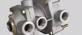
Air distributor KamAZ
With a single-wire drive, the connecting line is connected to terminal I. The supplied compressed air bends the edges of cuff 1 of piston 2 and passes into the trailer cylinder through terminal IV. The trailer chambers with outlet III are connected to the atmosphere through an open exhaust valve 5, a hollow valve sleeve 6 and atmospheric outlet II.
When the pressure in the line drops (braking), the pressure in terminal I also decreases, and piston 2, overcoming the resistance of spring 9, moves downward under the influence of pressure in terminal IV. Rod 3 and piston 4 move with it. In this case, the outlet valve 5 closes, and the inlet valve 7 opens, and compressed air from the trailer cylinder through terminal IV flows to terminal III and then to the trailer chambers. The tracking action is carried out by piston 4.
If the pressure in the connecting line increases (deceleration occurs), the process occurs in the reverse order. Pistons 2 and 4 move upward, inlet valve 7 closes, then exhaust valve 5 opens, connecting port III (brake chambers) to atmospheric port II.
In the case of a two-wire drive, the supply line is connected to terminal I, and the control (brake) line is connected to terminal V. The compressed air supplied through the supply line through cuff 1 of piston 2 enters the trailer cylinder through terminal IV.
When braking, compressed air supplied to terminal V acts on piston 11 and moves it down. Compressed air from the trailer cylinder enters the brake chambers connected to terminal III. The tracking action is carried out in this case by piston II.
The air distributor has a built-in equalizing valve 10. With a single-line drive, when the air pressure supplied to terminal I does not exceed 5.2 kgf/cm2, valve 10 does not work. In the case of a two-wire drive, when compressed air with a nominal pressure of 7 kgf/cm2 is supplied to terminal I, valve 10 opens and the pressure above and below piston 2 is equalized.
In the event of an emergency drop in pressure in the supply line, valve 10 initially remains open, and the pressure in the trailer cylinder also decreases. If the pressure in the line drops below 5.3 kgf/cm2, then valve 10 closes, and the pressure in the sight cylinder and above piston 2 does not change. With a further decrease in pressure in the line, the air distributor brakes the trailer in the same way as with a single-line drive.
Rice. 127. KamAZ air distributor:
I - output to the connecting or supply line; II - release into the atmosphere; III - output to the brake chambers; IV - output to the air balloon; V - output to the brake control line;
1 - cuff; 2 - piston; 3 - rod; 4 - internal piston; 5 — exhaust valve; 6 — valve sleeve; 7 — inlet valve; 8 - spring; 9 — balancing spring; 10 - equalizing valve; 11 - outer piston.
How to check the brake valve
Procedure for checking the brake system drive valve:
- Check the serviceability of the lamps and buzzer. To do this, you need to press the button located in the control lamp block; it should light up. The buzzer functions properly if at least 1 lamp lights up. Start the power unit and fill the pneumatic drive with air. In operating condition, filling the system takes no more than 8 minutes.
- Inspect the pneumatic system drive for leaks. It is necessary to turn off the compressor and lower the brake pedal. Within half an hour, the pressure level should drop to at least 0.5 kgf/cm². With consumers turned on, the pressure should reach this value within 15 minutes.
- Check the serviceability of the safety valves. A pressure gauge should be connected to the control valve. Then it is necessary to bleed the air flow from the front axle cylinder using a condensate drain valve. The level of pressure drop should be shown by only one arrow; the indicators in the cylinders of the rear cart and the parking brake system should not change.
- Check the serviceability of the pneumatic drive. The pressure gauge readings must correspond to the pressure level in the brake chambers of the rear cart and front axle.
Brake system. Part 1
Section 6. BRAKE SYSTEM.
KamAZ vehicles and road trains are equipped with four autonomous braking systems: service, spare, parking and auxiliary. Although these systems share common elements, they operate independently and provide high braking performance in all operating conditions. In addition, the vehicle is equipped with an emergency brake release drive, which makes it possible to resume movement of the KamAZ 4308 vehicle in the absence of compressed air in the brake system, an alarm system and control devices that allow monitoring the operation of the pneumatic drive.
The working brake system is designed to reduce the speed of the KamAZ 4308 vehicle or stop it completely. The brake mechanisms of the service brake system are installed on all four wheels of the Kamaz 4308 vehicle. The drive of the service brake system is a pneumatic dual-circuit system, it separately operates the brake mechanisms of the front axle and rear axle of the vehicle. The service brakes are controlled by a two-section brake valve with a suspended pedal mounted on the front panel of the cab;
The actuators of the service brake system drive are the brake chambers.
The parking brake system provides braking for a stationary KamAZ 4308 vehicle, including on a slope and in the absence of the driver, as well as for braking a moving KamAZ 4308 vehicle. The parking brake system is controlled by a hand crane that actuates the spring energy accumulators of the brake chambers installed on the rear axle of the vehicle .
The spare brake system is used to smoothly reduce the speed or stop a moving Kamaz 4308 vehicle in the event of partial failure of the service brake system. The function of the spare brake system is performed by the circuits of the service brake system.
The brake auxiliary system of the Kamaz 4308 vehicle serves to reduce the load and temperature of the brake mechanisms of the service brake system. The auxiliary braking system on KamAZ vehicles is an engine retarder, which, when activated, closes the engine exhaust pipe.
The alarm and control system consists of two parts:
— light and sound signaling about the operation of brake systems and their drives. The pneumatic drive receivers are equipped with pressure drop switches, which, if there is insufficient pressure in the receivers, close the signaling circuits located on the instrument panel, as well as the sound signal (buzzer) circuit. In addition, there is a brake signal switch, except for the auxiliary one, which closes the brake signal circuit when any of the following is triggered:
— control valves, which are used to diagnose the technical condition of the brake pneumatic drive, as well as, if necessary, take compressed air from the pneumatic system.
To emergency release the car in case of emergency movement, you need to screw the wing nut on the emergency brake release valve 29 (Fig. 6-2) all the way, then start the engine and set the valve handle 10 to the “Released” position. In this case, air from compressor 12 enters the energy accumulators through the two-line valve 17, bypassing the entire volume of the brake system, and after 20-30 s they will release the brakes (the “P” warning lamp in the indicator block will go out) and you can start moving. Braking in the absence of air in the working brake chambers must be done using valve 10. After the energy accumulators are released, air will begin to flow into the pneumatic drive of the brake system.
If the compressor or engine malfunctions, the KamAZ 4308 vehicle can be released using a mechanical brake release device. To do this, unscrew the screws of the emergency brake release mechanisms of the brake chambers with spring energy accumulators until they stop. In addition, the Kamaz 4308 vehicle can be released by connecting an external source of compressed air (garage compressed air network, car wheel, etc.), having a pressure of 600-785 kPa (6.0-.0 kgf/cm2), to tap 29 emergency release.
The auxiliary brake system mechanism (Fig. 6-1) is installed between the flange of the inlet pipe and the metal hoses. The mechanism consists of a spherical body 1 and a damper 3 mounted on a shaft 4. A rotary lever 2 connected to the pneumatic cylinder rod is also attached to the damper shaft. The lever and the associated flap have two fixed braking positions.
When the auxiliary brake system is turned off, the damper is installed along the flow of exhaust gases, and when turned on, it is installed across the flow, preventing their exit, thereby ensuring the occurrence of back pressure in the exhaust system.
At the same time, the fuel supply is stopped. The engine starts to operate in braking mode.
Rice. 6-1 Mechanism of the auxiliary brake system: 1 - damper shaft; 2 - body; 3 - damper; 4 - bushing; 5 - cover; 6 — rotary lever; 7 - rivet.
When you press button 1 (Fig. 1-4) of the auxiliary brake system control valve, compressed air from the consumer receiver enters pneumatic cylinder 6 (Fig. 6-4). The pneumatic cylinder rod connected to lever 6 (Fig. 6-1) of the flap of the auxiliary brake system mechanism will turn the flap and it will block the exhaust pipe of the muffler.
Rice. 6-4. Drive of the auxiliary brake system mechanism: 1 - air supply fitting from the four-circuit safety valve; 2 — auxiliary brake system control valve; 3 - connecting pipeline; 6 — pneumatic cylinder for controlling the auxiliary brake system mechanism; 8 — auxiliary brake system mechanism.
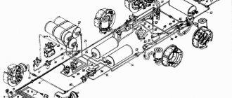
Drive of brake mechanisms.
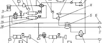
The schematic diagram of the drive is shown in Fig. 6-2 and 6-3. The source of compressed air in the drive is compressor 12. The compressor, cooler 11 and adsorbent dryer 13 constitute the supply part of the drive, from which purified compressed air under a given pressure is supplied in the required quantity to the remaining parts of the pneumatic brake drive and to other consumers of compressed air. The pneumatic brake drive is divided into autonomous circuits, separated from each other by a four-circuit safety valve. Each circuit operates independently of other circuits, including when faults occur.
Rice. 6-2. Diagram of the pneumatic drive of the brake systems of a single KAMA3-4308 car: 1 - type 24 brake chambers; 2 - pressure gauge; 3 — auxiliary brake system control valve; 5 — pneumatic cylinder for the flap drive of the auxiliary brake system mechanism; 6 — brake signal switch; 7 — two-section brake valve; 8, 9 — pressure drop sensors; 10 — parking brake system control valve; 11 — cooler; 12 - compressor; 13 - desiccant; 16 — four-circuit safety valve; 17 — two-line bypass valve; 18 — automatic brake force regulator; 19 — accelerator valve; 20 — receiver circuit II; 21 — receiver of circuit I; 22 — brake chamber 20/20 with a spring energy accumulator; 23 — parking brake warning lamp sensor; 27 — modulators of the anti-lock braking system; 28 — ABS speed sensor; 29 — emergency brake release valve; 30 - regeneration receiver. A - air intake valve for inflating tires. B, C, D, E - valves of control terminals. I - to the compressed air consumer.
Circuit I of the drive of the working brake mechanisms of the front axle (Fig. 6-2 and 6-3) consists of part of a four-circuit safety valve 16; receiver 21 with a capacity of 20 liters with a condensate drain valve and a pressure drop sensor 8 installed in the lower section of the brake valve 7, part of a two-pointer pressure gauge 2; lower section of two-section brake valve 7; control valve (C); two brake chambers 1; brake mechanisms of the front axle of the car, pipelines and hoses between these devices, two modulators 27 and two sensors 28.
Rice. 6-3. Diagram of the pneumatic drive of the brake systems of the KAMA3-4308 tractor: 1 - type 24 brake chambers; 2 - pressure gauge; 3 — auxiliary brake system control valve; 5 — pneumatic cylinder for driving the flaps of the auxiliary brake system mechanism; 6 — brake signal switch; 7 — two-section brake valve; 8, 9 — pressure drop sensors; 10 — parking brake system control valve; 11 — cooler; 12 - compressor; 13 - desiccant; 14 — receiver of circuit III, 16 — four-circuit protective valve; 17 — two-line bypass valve; 18 — automatic brake force regulator; 19 — accelerator valve; 20 — receiver circuit II; 21 — receiver of circuit I; 22 — brake chamber 20/20 with a spring energy accumulator; 23 — parking brake warning lamp sensor; 24 — trailer brake control valve; 25, 26 — automatic connection heads (supply and control); 27 — modulators of the anti-lock braking system; 28 — ABS speed sensor; 29 — emergency brake release valve; 30 - regeneration receiver. A - air intake valve for inflating tires. B, C, D, E - valves of control terminals. I - to the compressed air consumer;
Circuit II of the drive of the working brake mechanisms of the rear axle consists of a part of the four-circuit safety valve 16 (Fig. 6-2 and 6-3); receiver 20 with a capacity of 20 liters with condensate drain valves and a pressure drop sensor 9 installed in the upper section of the brake valve 7; parts of two-pointer pressure gauge 2; upper section of two-section brake valve 7; control output valve (D), automatic brake force regulator 18 with an elastic element; two brake chambers 22; rear axle brake mechanisms; pipelines and hoses between these devices, two modulators 27 and two sensors 28.
Circuit III of the drive of the parking brake system mechanisms (Fig. 6-2) consists of part of a four-circuit safety valve 16, a receiver 14 with a capacity of 20 liters (only for a tractor) with a condensate drain valve and a pressure drop sensor in the receiver, two valves 7 control output (B and E) a manual brake valve 10, an accelerator valve 19, a part of a two-line bypass valve 17, two spring energy accumulators 22, a parking brake warning lamp sensor 23 and hoses between these devices. It should be noted that the pneumoelectric sensor 23 in the circuit is installed in such a way that it ensures that the “brake light” lamps turn on when the car is braking.
Circuit IV of the drive of the auxiliary brake system and other consumers (Fig. 6-2 and 6-3) consists of a four-circuit safety valve section 16; pneumatic crane 3; cylinder 5 of the gas-dynamic brake mechanism damper drive; tubes and hoses between these devices; highways of additional consumers.
From circuit IV, compressed air is supplied to additional consumers: to the pneumatic signal, clutch pneumatic booster, control of transmission units, etc.
To monitor the operation of the pneumatic brake drive and timely signal about its condition and emerging malfunctions in the cockpit, there are five warning lights on the instrument panel, a two-pointer pressure gauge indicating the compressed air pressure in the receivers of two circuits (I and II) of the pneumatic drive of the service brake system, and a buzzer , signaling an emergency drop in compressed air pressure in the receivers of any brake circuit.
Pneumatic brake drive devices
The compressor (Fig. 6-4) is piston type, single-cylinder, single-stage compression. Capacity 380 l/min at a back pressure of 0.7 mPa (7 kgf/cm2) and engine speed 2200 min-1. The compressor is mounted on the front end of the engine flywheel housing.
Aluminum piston with floating pin. The axial movement of the pin is secured in the piston bosses by thrust rings. Air from the engine manifold enters the compressor cylinder through the reed inlet valve. The air compressed by the piston is forced into the pneumatic system through a plate discharge valve located in the cylinder head.
The head is cooled by liquid supplied from the engine cooling system.
The adsorbent dryer (Fig. 6-5) with a built-in pressure regulator from Wabko Westingaus (Germany) is designed to separate condensate from compressed air and automatically remove it from the supply part of the drive.
Rice. 6-4. Compressor: 1 — connecting rod; 2 — piston pin; 3 - oil scraper ring; 4 - compression ring; 5 — compressor cylinder body; 6 — cylinder spacer; 7 — cylinder head; 8 - coupling bolt; 9 - nut; 10 - gaskets; 11 - piston; 12, 13 — sealing rings; 14 — plain bearings; 15 — rear crankcase cover; 16 - crankshaft; 17 — crankcase; 18 — drive gear; 19 — gear nut; I - input; II - output to the pneumatic system.
Drying of the compressed air supplied by the compressor is carried out using adsorption drying of cold regeneration, when the air compressed by the compressor is blown through granules (adsorbent), which is able to absorb water vapor contained in the air.
Rice. 6-5. Air dryer 432 410…O
During the filling phase of the system, the compressed air pumped by the compressor enters chamber A through inlet 1. Here, condensate formed as a result of a decrease in temperature flows through channel C into the outlet (e).
The air through the fine filter (g) and the annular chamber (h) built into the cartridge tends to the top of the granulate cartridge (b). When passing through the granulate (a), moisture is removed from the air and deposited in its surface layer (a). The dried air through the check valve (c), input 21 and connected brake devices enters the brake system receivers. At the same time, the dried air enters the regeneration receiver through the throttle opening and inlet 22.
Air enters through opening (i) into chamber D and the cut-off pressure acts on the membrane (m). After overcoming the spring force, the inlet port (n) opens, and then the piston (d), under the influence of pressure, opens the outlet port (e).
Now the air pumped by the compressor flows into the atmosphere through chamber A, port C and outlet 3. At the same time, piston (d) takes on the function of a safety valve. When excess pressure occurs, piston (d) automatically opens outlet (e).
If the pressure in the device drops due to air flow below the cut-in pressure, the inlet (n) is closed and the pressure in chamber B is reduced by releasing air through the regulator. The outlet (e) closes and the drying process begins again.
Air bleed valve for tire inflation. When screwing on the hose fitting for inflating tires, the valve is recessed, allowing access to compressed air into the hose and blocking the flow of compressed air into the brake system.
The four-circuit safety valve (Fig. 6-6) is designed to divide the compressed air coming from the compressor into four circuits; to automatically shut down one of the circuits if its seal is broken and preserve compressed air in sealed circuits; to preserve compressed air in all circuits in the event of a leak in the supply line; to power additional circuits from two main circuits (until the pressure in them drops to a given level). The four-circuit safety valve is attached to the side member of the vehicle frame.
Compressed air entering the four-circuit protective valve from the supply line, upon reaching the specified opening pressure set by the force of the springs 3, opens the valves 7, acting on the membrane 5, lifts it, and enters through the terminals into the two main circuits.
After opening the check valves, compressed air enters the valves 7, opens them and passes through the outlet into the additional circuit.
If the tightness of one of the main circuits is broken, the pressure in this circuit, as well as at the inlet to the valve, drops to a predetermined value. As a result, the valve of the serviceable circuit and the check valve of the additional circuit are closed, preventing a decrease in pressure in these circuits. Thus, in healthy circuits a pressure will be maintained corresponding to the opening pressure of the valve of the faulty circuit, while an excess amount of compressed air will escape through the faulty circuit.
If the auxiliary circuit fails, the pressure drops in the two main circuits and at the valve inlet. This happens until valve 6 of the additional circuit closes.
With the further supply of compressed air to the safety valve 6 in the main circuits, the pressure will be maintained at the level of the opening pressure of the valve of the additional circuit.
Rice. 6-6. Four-circuit protective valve: 1 — protective cap; 2 — spring plate; 3, 8, 10 — springs; 4 — spring guide; 5 - membrane; 6 — pusher; 7, 9 — valves; 11, 12 — screws; 13 — traffic jam; 14 — body; 15 - cover.
Rice. 6-7. Condensate drain valve: 1 - rod; 2 - spring; 3 - body; 4 — support ring; 5 — washer; 6 - valve.
The condensate drain valve (Fig. 6-7) is designed for forced draining of condensate from the receiver of the pneumatic brake drive, as well as for releasing compressed air from it if necessary. The condensate drain valve is screwed into the threaded boss on the bottom of the receiver body. The connection between the tap and the receiver boss is sealed with a gasket.
Receivers are designed to accumulate compressed air produced by a compressor and to power pneumatic brake drive devices, as well as to power other pneumatic components and systems of the vehicle.
The receivers are secured with clamps to the frame brackets.
The two-section brake valve (Fig. 6-8) is used to control the actuators of the dual-circuit drive of the vehicle's service brake system.
The valve is controlled by a pedal directly connected to the brake valve.
Rice. 6-8. Brake valve driven by a pedal: 1 - pedal; 2 — adjusting bolt; 3 — protective cover; 4 — roller axis; 5 - roller; 6 — pusher; 7 - base plate; 8 - nut; 9 - plate; 10, 16, 19, 27 - sealing rings; 11 — hairpin; 12 — follower piston spring; 13, 24 — valve springs; 14, 20 — valve spring plates; 15 — small piston; 17 — valve of the lower section; 18 — small piston pusher; 21 - atmospheric valve; 22 - thrust ring; 23 — atmospheric valve body; 25 — lower body; 26 — small piston spring; 28 - large piston; 29 — valve of the upper section; 30 — follower piston; 31 - elastic element; 32 — upper body; A - hole; B - cavity above the large piston; I, II - input from the receiver; III, IV - output to the brake chambers of the rear and front wheels, respectively.
The crane has two independent sections located in series. Inputs I and II of the valve are connected to the receivers of two separate drive circuits of the service brake system. From terminals III and IV, compressed air flows to the brake chambers. When you press the brake pedal, the force is transmitted through the pusher 6, plate 9 and elastic element 31 to the follower piston 30. Moving down, the follower piston 30 first closes the outlet hole of the valve 29 of the upper section of the brake valve, and then lifts the valve 29 from the seat in the upper housing 32, opening the passage of compressed air through input II and output III and further to the actuators of one of the circuits. The pressure at terminal III increases until the force pressed on pedal 1 is balanced by the force created by this pressure on piston 30. This is how the tracking action is carried out in the upper section of the brake valve. Simultaneously with the increase in pressure at port III, compressed air through hole A enters cavity B above the large piston 28 of the lower section of the brake valve. Moving down, the large piston 28 closes the outlet of the valve 17 and lifts it from the seat in the lower housing. Compressed air through input I enters output IV and then into the actuators of the first circuit of the service brake system.
Simultaneously with the increase in pressure at terminal IV, the pressure under the pistons 15 and 28 increases, as a result of which the force acting on the piston 28 from above is balanced. As a result, a pressure corresponding to the force on the brake valve lever is also established at terminal IV. This is how the tracking action is carried out in the lower section of the brake valve.
If the upper section of the brake valve fails, the lower section will be controlled mechanically through the pin 11 and the pusher 18 of the small piston 15, maintaining full functionality. In this case, the tracking action is carried out by balancing the force applied to pedal 1 with air pressure on the small piston 15. If the lower section of the brake valve fails, the upper section works as usual.
The parking brake system control valve (Fig. 6-9) is designed to control the spring energy accumulators of the drive of the parking and spare brake systems.
When the vehicle is moving, the valve handle 14 is in a horizontal position, and compressed air from the drive receiver of the parking and spare brake systems is supplied through input I. Under the action of spring 6, rod 16 is in the lowest position, valve 22 is pressed against the outlet seat 21 of the rod by the force of spring 2 16. Compressed air through the holes in the piston 23 enters the cavity L, and through the inlet seat of the valve 22, which is made at the bottom of the piston 23, into the cavity B, then through the vertical channel in the housing 3 the air passes to the terminal Ш and further to the spring energy accumulators of the drive .
When the position of the handle 14 changes, the guide cap 15 rotates together with the cover 13. Sliding along the screw surfaces of the ring 9, the cap 15 rises up and carries the rod 16 with it. The seat 21 comes off the valve 22, and the valve, under the action of the spring 2, rises until it stops in the seat piston 23. As a result, the passage of compressed air through input I to output III stops; through the open outlet seat 21 on the rod 16, compressed air through the valve 22 leaves port III into the atmospheric port II until the air pressure force in cavity A under the piston 23 overcomes the forces of the balancing spring 5 and the air pressure above the piston in cavity B. Overcoming the force of the spring 5, the piston 23 together with the valve 22 rises up until the valve comes into contact with the outlet seat 21 of the rod 16, after which the release of air stops. In this way, a tracking action is carried out.
Rice. 6-9. Parking brake system control valve: 1.10 - thrust rings; 2 — valve spring; 3 - body; 4, 24 — sealing rings; 5 - balancing spring; 6 — rod spring; 7 — balancing spring plate; 8 — rod guide; 9 — figured ring; 11 - pin; 12 — cap spring; 13 - cover; 14 — valve handle; 15 — guide cap; 16 — rod; 17 — roller axis; 18 — clamp; 19 — roller; 20 - stopper; 21 — valve outlet seat on the stem; 22 - valve; 23 — follower piston; I - input from the receiver; II - atmospheric output; III - output of the control line of the accelerator valve
The valve stopper 20 has a profile that ensures that the handle automatically returns to the lower position when it is released. Only in the uppermost position does the lock 18 of the handle 14 fit into a special cutout of the stopper 20 and fixes the handle. In this case, the air from port III completely escapes into the atmospheric port II, since the piston 23 rests against the plate 7 of the spring 5 and the valve 22 does not reach the outlet seat 21 of the rod.
To release the spring energy accumulators, the crane handle must be pulled out in the radial direction, while the latch 18 comes out of the stopper groove, and the handle 14 freely returns to the lower position.
A pneumatic valve (Fig. 6-10) with push-button control is designed to supply and shut off compressed air. Two such cranes are installed on the KamAZ vehicle. One controls the emergency braking system for spring energy accumulators, the second controls the pneumatic cylinder of the auxiliary brake system.
Rice. 6-10. Pneumatic valve: 1, 11, 12 - thrust rings; 2 - body; 3 - filter; 4-plate spring rod; 5, 10, 14 — sealing rings; 6 — bushing; 7 — protective cover; 8 — button; 9 — pusher; 13 — pusher spring; 15 — valve: 16 — valve spring; 17 — valve guide. I - from the supply line; II - into the atmosphere; III - to the control line.
The design of a pneumatic valve is shown in Fig. 6-10. A filter 3 is installed in the atmospheric outlet II of the pneumatic valve, which prevents dirt and dust from entering the valve. Compressed air enters the pneumatic valve through outlet I. When you press button 8, pusher 9 moves down and with its outlet seat presses on valve 15, disconnecting outlet III from atmospheric outlet II. Then the pusher 9 presses the valve 15 from the inlet seat of the housing, thereby opening the passage of compressed air from outlet I to outlet III and further into the line to the pneumatic actuator.
When button 8 is released, pusher 9 returns to the upper position under the action of spring 13. In this case, valve 15 closes the hole in housing 2, stopping further flow of compressed air into terminal III, and the pusher seat 9 comes off valve 15, thereby connecting terminal III with atmospheric terminal II. Compressed air from port III through hole A in pusher 9 and port II escapes into the atmosphere.
How to adjust
The brake valve is adjusted as follows:
- Close the tap.
- Connect a pressure gauge to the connection head.
- Increase the pressure in the receiver to 7.3 kgf/cm².
- Check the pressure gauge readings, which should match the pressure in the receiver.
- If the device shows a low pressure level, check the position of the spring mechanism. It should be pressed against the stop.
- Set the emergency brake system lever to the “On” position.
- Turn the plate clockwise. 1 revolution increases the pressure level by 2 kgf/cm². It is necessary to make the number of revolutions that will make up for the difference in the readings of the pressure gauge and the receiver.
- Set the parking brake to the “Off” position.
- Check the pressure gauge readings.
- Adjust the brake valve drive from the service brake system.
- Lower the brake pedal and adjust the length of the pull rod.
- Lock the fork with the fastening nut so that the lever is in contact with the stop part of the tap.
- Lower the adjusting bolt.
- Adjust the position of the handle so that its upper part touches your finger.
- Adjust the lever stroke by rotating the adjusting bolt.
How to replace
Procedure for replacing a tap:
- Release the air flow from the pneumatic drive receivers located on the rear and front axles.
- Remove the union mounting screws that connect the ends of the pneumatic lines.
- Unpin and remove the connecting pin from the rear fork of the traction mechanism with the crane lever.
- Unscrew the nuts of the mounting bolts that connect the upper housing plate to the bracket.
- Remove damaged or worn crane mechanism.
- Install the new part onto the side member bracket, which is located on the left side.
- Secure the mechanism using fasteners.
- Connect the tap to the rear link fork handle. The connection and distribution diagram is in the KamAZ user manual.
- Install and pin the pin.
- Connect the tips of the pneumatic pipelines to the tees and transition elements.
- Tighten the mounting nuts.
- Start the engine.
- Fill the pneumatic drive of the brake systems with air.
- Check the tightness of all pipelines and the main brake valve.
- Check the pressure level in the receiver part of the mechanism.
Description of KamAZ brakes
The brake system consists of four sections - main, parking, auxiliary and spare. They have a similar structure, but they work separately. Therefore, if one system is completely malfunctioning, the multi-ton loaded vehicle will be stopped by the remaining three units. Their controls are located in a convenient location for the driver, so that he can use each of the blocks in any situation.
Departments of the brake system Kamaz-5320
Basic
Designed to control a car while driving. It has a pneumatic drive that controls the front and rear wheels separately. The main parts of the KamAZ brake system are the drum and pads. Because of these elements, the entire unit most often fails, since they experience the greatest loads and wear out.
Spare
It is used to change speed and stop when a malfunction occurs in the main brake unit. It is combined with the parking brake by some common mechanisms. It includes:
Pneumatic brake drive of the KamAZ-5320 vehicle
- 4 springs;
- 2 air cylinders;
- safety valve;
- pressure meter;
- brake valve;
- pipelines;
- hoses.
The spare system is activated by a parking lever, which is moved to an intermediate position (between horizontal and vertical).
Auxiliary
This braking system works from the energy of the car rolling down an inclined plane, and the engine is used to stop it. The braking process is started by pressing the button next to the steering column. After this, the compressed air begins to move from the safety valve to the brake cylinders. The path to exhaust gases is blocked, and the engine at this time acts as a compressor. Pressure is directed to the pads and drum, which results in braking.
Kamaz brake accelerator valve
Parking block
This system holds the vehicle in place during short stops or long periods of parking.
The KamAZ design includes an emergency brake release mechanism. It compresses those springs that are used when using the parking or spare unit. There is a button on the panel for activation. If necessary, you can use a mechanical method of releasing the brakes by unscrewing the special screws of the energy storage springs.
Brake valve repair
Repair of the KamAZ crane brake mechanism is carried out as follows:
- It is necessary to unpin and dismantle the pin of the traction device.
- Then unscrew the 4 mounting bolts from the bracket.
- It is necessary to unscrew the air lines that lead to the tap. Using a punch, mark the location of the air channels relative to the highways.
- After this, unscrew the 4 bolts from the base plate body using a 12mm wrench.
- Then dismantle the upper part of the faucet body along with the handle and separate the plate.
- Finally, remove the upper piston mechanism.
If the problem is that the faucet hisses, then it is necessary to restore the seal of the piston part. To do this, you need to replace the damping device, which dampens sudden shocks from the handle.
To replace the damper, you need to maintain the previous position of the screw and adjust the gap between the screw and the pushing part of the piston.
If the breakdown was caused by a malfunction of the valve, you need to unscrew the mounting screws, disconnect the housing and pull out the small piston, swinging the large one.
To restore the tightness, it is necessary to isolate the upper and lower sections of the sealing rings, bleed out the air, and replace the damaged parts with new ones.
Types of repair kits
There are several sets of repair tools for removing malfunctions in the brake valve:
- Small set. It only includes the sealing items and a special protective cover for the control lever.
- Average set. In addition to the contents of the previous set, it is equipped with bushings and fasteners.
- Large set. This option contains a complete set of necessary elements for self-repair of the brake valve.
6.1.6. Two-section brake valve. Device
Two-section brake valve (Fig. 101). Designed to control the mechanisms of the service brakes of a vehicle and drive the brake control valves of a semi-trailer in the presence of a separate drive to the brakes of the front and rear axles. The crane has two independent sections, located in series, powered by separate circuits and controlling: the lower one - the front axle brakes, the upper one - the rear axle brakes and the semi-trailer brakes. The faucet valves are flat, single, rubber. Terminals I and II of the upper and lower sections are connected to the air cylinders of the rear and front circuits, respectively, and terminals III and IV are connected to the brake chambers of the rear and front axles. In the initial position (the brake pedal is released), the brake valve communicates with the atmosphere to the brake chambers through valve 21. In this case, the piston 30 of the upper section, under the action of the spring 12, occupies the uppermost position, the valve outlet window is open, and terminal III is connected to the atmosphere. The upper valve 29, under the action of the spring 13, is pressed against the seat of the upper housing, and terminal II is disconnected from terminal III. The large 25 and small 15 piston under the action of the spring 26 are in the uppermost position, the outlet window of the lower valve 17 is open, terminal IV is connected to the atmosphere. The lower valve 17 is pressed against the seat of the lower housing by a spring 24 and terminal I is disconnected from terminal IV. When you press the brake pedal, lever 1 rotates on its axis 4, roller 5 presses on pusher 6, which, through plate 9, displaces damper 31 and moves piston 30 down. The piston, moving down, compresses spring 12, closes the outlet window, disconnecting terminal III from the atmosphere, and opens valve 29 from the seat. The compressed air supplied to terminal I is supplied through the open valve to terminal III and then to the brake chambers of the rear axle until the force of pressing the lever is balanced by the air pressure on the piston 30 (following action). At the same time, compressed air through the hole in outlet III is supplied to the above-piston space of the large piston 28. The piston 28, which has a large surface, moves downward with a small pressure in the above-piston space and moves the small piston 15, compressing the spring 26. The small piston 15 closes the outlet window, disconnecting conclusions IV from the atmosphere, and tears off valve 17 from the seat. Compressed air supplied to terminal II through the open valve is supplied to terminal IV and then to the brake chambers of the front axle. The compressed air located in the space under the pistons 15 and 28 balances the force acting on the piston 28 from above in such a way that a pressure is established in cavity IV corresponding to the force of pressing the lever (following action). The dimensions of the pistons and spring 26 are selected so that the pressure in terminals III and IV, depending on the force on the lever, is almost the same; at intermediate lever positions, the lower section is controlled pneumatically. When the lever is in the extreme position or in case of damage to the contour of the upper section, the piston 30, moving downwards, with the pin 11 acts on the rod 18 of the small piston 15, moving it. The small piston, in turn, closes the outlet window and opens valve 17. When the force is removed from the lever, the upper piston moves upward under the action of spring 12, valve 29 is pressed against the seat, and the piston, continuing to move, opens the outlet window and communicates terminal III with the atmosphere . The pressure in the above-piston space of the large piston 28 drops, pistons 28 and 15 move upward due to the pressure difference and the action of spring 26, valve 17 is pressed against the seat, the outlet window opens, and terminal IV communicates with the atmosphere. When there is a mechanical effect on the small piston 15, the lower section is braked when the force is removed from the rod 18.
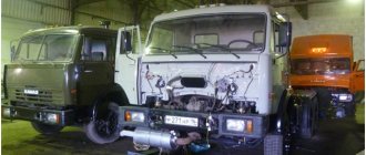
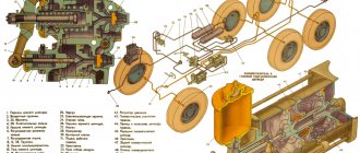
The design of the brake system of KamAZ vehicles
The principle of operation of the brake system is as follows. After pressing the brake pedal, all the pressure goes to the booster. It affects the operation of the main cylinder of the brake system. The cylinder consists of pistons, which are affected by excess fluid produced. This process ensures the movement of the pads to the brake discs and the passage of energy into the drive.
Control of the main and auxiliary mechanisms transmits a signal to the parking unit. This stops the vehicle. After stopping is completed, the return mechanism circuit comes into operation, thus the brake pedal ceases to be active. The main cylinder pistons also return to their standard position.
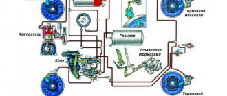
The figure below shows a description of the design of the KamAZ brake system.
Diagram of the KamAZ brake system
Have you ever encountered a brake valve failure in a KamAZ truck?
Source
Brake system
SECTION 6. BRAKE SYSTEM The vehicle is equipped with service, parking, spare and auxiliary brake systems. Although these braking systems have common elements, they operate independently of each other and provide the necessary braking performance in all operating conditions. In addition, the car is equipped with an alarm and control devices that allow you to monitor the operation of the pneumatic drive. The vehicle is also equipped with brake devices for connecting the trailer brake system with both a single-line pneumatic drive and a two-line drive.
The braking system of cars is shown in Fig. 6-1, 6-2, 6-3.
Rice. 6-1. Diagram of the pneumatic brake drive of KAMAZ-4350 and -43501 vehicles: 1 - front brake chambers; 2 (A, C, D, E) - control terminals; 3 — regeneration receiver; 4 — auxiliary brake system control valve; 5 — two-pointer pressure gauge; 6 - compressor; 7 — pneumatic cylinder for driving the engine stop lever; 8 - heat exchanger; 9 — adsorbent dryer with pressure regulator; 10 — tire inflation valve; 11 — two-line bypass valve; 12 - 4-circuit safety valve; 13 — parking brake system control valve; 15 — two-section brake valve; 17 — pneumatic cylinders for driving the flaps of the auxiliary brake system mechanism; 18 — receiver of circuit I; 19 — receiver circuit II; 20 — pressure regulator; 21 — receiver of circuit III; 22 — receiver circuit IV; 23 — condensate drain valve; 24 — rear brake chambers with spring energy accumulators; 25, 26 — accelerator valve; 28 — control valve for trailer brake systems with a two-wire drive; 29 — control valve for trailer brake systems with a single-wire drive; 30 — moisture separator; 32 — emergency brake release valve; 33 — brake signal switch; 34, 35, 36, 37 - pressure drop sensor in circuits I, II, III and IV, respectively; 38 — sensor (parking brake warning lamp); 39 — brake force regulator; 40 — automatic connecting head (R — to the supply line of the two-wire drive, N — to the control line of the two-wire drive); 41 - connection head type A.
Rice. 6-2. Diagram of the pneumatic brake drive of KAMAZ-5350, -53501, -53504 vehicles: 1 - front brake chambers; 2 (A, C, D, E) - control terminals; 3 — regeneration receiver; 4 — auxiliary brake system control valve; 5 — two-pointer pressure gauge; 6 - compressor; 7 — pneumatic cylinder for driving the engine stop lever; 8 - heat exchanger; 9 — adsorbent dryer with pressure regulator; 10 — tire inflation valve; 11 — two-line bypass valve; 12 - 4-circuit safety valve; 13 — parking brake system control valve; 15 — two-section brake valve; 17 — pneumatic cylinders for driving the flaps of the auxiliary brake system mechanism; 18 — receiver of circuit I; 19 — circuit receiver I; 20 — pressure regulator; 21 — receiver of circuit III; 22 — receiver circuit IV; 23 — condensate drain valve; 24 — rear brake chambers with spring energy accumulators; 25, 26 — accelerator valve; 28 — control valve for trailer brake systems with a two-wire drive; 29 — control valve for trailer brake systems with a single-wire drive; 30 — moisture separator; 32 — emergency brake release valve; 33 — brake signal switch; 34, 35, 36, 37 - pressure drop sensor in circuits I, II, III and IV, respectively; 38 — sensor (parking brake warning lamp); 39 — brake force regulator; 40 — automatic connecting head (R — to the supply line of the two-wire drive, N — to the control line of the two-wire drive); 41 - connection head type A.
The service braking system is designed to reduce the speed of the vehicle or stop it completely. It allows you to safely and quickly stop a moving vehicle. The brake mechanisms of the service brake system are installed on all wheels of the vehicle. The drive of the service brake system is pneumatic, dual-circuit, separate for the brake mechanisms of the front axle and the rear bogie of the vehicle. It is controlled by a two-section brake valve located on the front panel of the cab.
The parking brake system provides braking for a stationary vehicle, including on a slope and in the absence of the driver. It is allowed to use it to stop a moving vehicle only in emergency cases, when the service brake system fails, as well as for braking in difficult road conditions, when there is ice, and to “stretch” the road train. The spare brake system is designed to smoothly reduce the speed or stop a moving vehicle in the event of complete or partial failure of the service brake system.
Rice. 6-3. Diagram of the pneumatic brake drive of the KAMAZ-6350, -63501, -6450 vehicle: 1 - front brake chambers; 2 (A, C, D, E) - control terminals; 3 — regeneration receiver; 4 — auxiliary brake system control valve; 5 — two-pointer pressure gauge; 6 - compressor; 7 — pneumatic cylinder for driving the engine stop lever; 8 - heat exchanger; 9 — adsorbent dryer with pressure regulator; 10 — tire inflation valve; 11 — two-line bypass valve; 12 - 4-circuit safety valve; 13 — parking brake system control valve; 15 — two-section brake valve; 17 — pneumatic cylinders for driving the flaps of the auxiliary brake system mechanism; 18 — receiver of circuit I; 19 — receiver circuit II; 20 — pressure regulator; 21 — receiver of circuit III; 22 — receiver circuit IV; 23 — condensate drain valve; 24 — rear brake chambers with spring energy accumulators; 25, 26, 27 — accelerator valve; 28 — control valve for trailer brake systems with a two-wire drive; 29 — control valve for trailer brake systems with a single-wire drive; 30 — moisture separator; 32 — emergency brake release valve; 33 — brake signal switch; 34, 35,36, 37 - pressure drop sensor in circuits I, II, III and IV, respectively; 38 — sensor (parking brake warning lamp); 39 — brake force regulator; 40 — automatic connecting head (R — to the supply line of the two-wire drive, N — to the control line of the two-wire drive); 41 - connection head type A.
For cars of all models, the role of a spare brake system is performed by circuits I and II of the service brake systems. The two-section brake valve has two independently operating sections, with the help of which the vehicle is braked. The intensity of braking by an intact circuit depends on the degree of pressing on the brake valve pedal.
The vehicle's auxiliary braking system serves to reduce the load on the brake mechanisms of the service brake system. The auxiliary braking system is a gas-dynamic braking mechanism in the exhaust system, when activated, the engine exhaust pipes are blocked, the fuel supply is turned off and provides increased engine braking efficiency.
The alarm and control system consists of two parts: light and sound signaling about the operation of brake systems and their drives. The drive receivers are equipped with pressure drop switches, which, if there is insufficient pressure in the receivers, close the signaling circuits located on the instrument panel panel, as well as the sound signal (buzzer) circuit. There is also a brake light switch that closes the brake light circuit when the service brake system is applied. The system also contains control valves, which are used to diagnose the technical condition of the brake pneumatic drive, and also, if necessary, remove compressed air from the pneumatic system.
Technical characteristics of brake systems
| Brakes | Drum type with two inner shoes and S-knuckle expansion device |
| Drum diameter, mm | 400 |
| Width of pads, mm | 140 |
| Adjustment lever length, mm | See fig. 6-36 and 6-37 |
| Brake chambers — front axle: - rear trolley | Type 24, membrane Type 24/20 or 24/24, membrane with spring energy accumulators |
| Compressor | Piston type, single-cylinder, liquid-cooled head and forced lubrication |
| Cylinder diameter and piston stroke, mm | 92×46 |
| Productivity at back pressure 700 kPa (7 kgf/cm2) and crankshaft speed 2200 min-1, l/min | 380 |
| Drive unit | Gear, through the gears of the drive units; gear ratio 0.94 |
| Backpressure in the exhaust system with the valves of the auxiliary brake system mechanism closed, kPa (kgf/cm2), max | 250 (2,5) |
Pneumatic drive of brake systems
The pneumatic drive consists of four autonomous circuits, separated from one another by a four-circuit safety valve. Each circuit operates independently of other circuits, including when faults occur.
Circuit I of the drive of the working brake mechanisms of the front axle consists of a part of a four-circuit safety valve 12; receiver 18 (in Fig. 6-3 - two receivers 18) with a condensate drain valve and a pressure drop sensor 34 installed in the lower section of the brake valve 15, part of a two-pointer pressure gauge 5; lower section of a two-section brake valve 15; control valve A; two brake chambers 1; accelerator valve 27 (Fig. 6-3); brake mechanisms of the front axle of the car, pipelines and hoses between these devices.
In addition, the circuit includes air supply pipes from the lower section of the brake valve 15 to the trailer brake system control valve 28 (Fig. 6-1, 6-2 and 6-3).
Circuit II of the drive of the working brake mechanisms of the rear axle (rear bogie) consists of part of a four-circuit safety valve 12; 19 receivers with condensate drain valves and a pressure drop sensor 35 installed in the upper section of the brake valve; parts of a two-pointer pressure gauge 5; the upper section of the two-section brake valve 15; brake force regulator 39; accelerator valve 26; control valves C and E; brake chambers 24; brake mechanisms of the rear axle (rear bogie); pipelines and hoses between these devices. The circuit also includes tubes from the upper section of the brake valve 15 to the trailer brake system control valve 28 (Fig. 6-1, 6-2 and 6-3).
Circuit III of the drive mechanisms of the parking brake system consists of a part of a four-circuit safety valve 12; receiver 21 with control valve D; pressure drop sensor 36 in the circuit; parts of a two-line bypass valve 11; accelerator valve 26 with sensor (parking brake warning lamp) 38; parking brake system control valve 13; control valve D; hoses between these devices; valve 28 for controlling the trailer brake systems and two automatic heads 40N and 40R for the two-wire drive of the trailer brake systems. Three-wire brake circuits also include a single-wire trailer brake control valve 29 and a Type A connection head 41P.
Circuit IV of the drive of the auxiliary brake system and other consumers consists of a section of a four-circuit safety valve 12; receiver 22 with condensate drain valve 23 and pressure drop sensor 37 in the receiver; auxiliary brake system control valve 4 (item 2, Fig. 6-8); pneumatic cylinder 7 for driving the engine stop lever; pneumatic cylinders 17 for driving the flaps of the auxiliary brake system mechanism; hoses between these devices; highways of additional consumers.
From circuit IV, compressed air is supplied to additional consumers: to the clutch pneumatic booster, control of transmission units, etc.
To monitor the operation of the pneumatic brake drive and timely signal about its condition and emerging malfunctions in the cockpit, there are five warning lights on the instrument panel, a two-pointer pressure gauge indicating the compressed air pressure in the receivers of two circuits (I and II) of the pneumatic drive of the service brake system, and a buzzer , signaling an emergency drop in compressed air pressure in the receivers of any brake circuit.
The brake pneumatic drives of the tractor and trailer connect three lines: the line of the single-wire drive, the supply and control brake lines of the two-wire drive. The coupling heads are mounted on the rear cross member of the frame.
The operation of the pneumatic drive of brake systems is as follows. Compressed air from compressor 6 through heat exchanger 8, dryer 9 (or moisture separator 30) is supplied to a 4-circuit safety valve and a two-line bypass valve 11, which distribute the air to receivers 18, 19, 21 and 22 independent circuits 1, IV, III, respectively , II and emergency release circuit.
Working brake system. When the brake system is filled, air from receivers 18 and 19 enters the corresponding sections of the brake valve 15. When you press the brake pedal, air from the lower section of the brake valve enters the brake chambers 1, which activate the brake mechanisms of the front axle wheels. From the upper section of the valve, air is supplied as a control to the accelerator valve 25, opens it, and compressed air from the receivers 19 is supplied to the brake chambers 24, which actuate the brake mechanisms of the wheels of the intermediate and rear axles. At the same time, from both sections of the brake valve, air flows through separate lines to valve 28 for controlling the brake systems of a trailer with a two-wire drive. Valve 28 opens to allow air to flow to valve 29 for single line trailer brake control.
When the pedal is released, compressed air from the front brake chambers, as well as from the control lines of the trailer brake control valve with a two-line drive, is released into the environment through a two-section brake valve, as well as from the rear brake chambers through an accelerator valve. The car and trailer are released.
Parking brake system. To brake a car or road train while parked, the handle of valve 13 for controlling the parking brake system must be set to a vertical fixed position. In this case, the air through the atmospheric outlet of the valve from the control line of the accelerating valve 26 and connecting pipelines escapes into the environment. Through the atmospheric outlet of the accelerator valve, air is released from the cylinders of the spring energy accumulators of the brake chambers 24. The springs, unclenching, actuate the brake mechanisms of the rear and intermediate axles. At the same time, the drop in pressure in the connecting line causes the trailer brake control valves with two-wire 28 and single-wire 29 drives to operate and to supply command pressure to the connecting heads.
To turn off the parking brake system, the valve handle 13 must be set to a horizontal position. In this case, air from the brake valve 13 enters the control line of the accelerator valve 26, which is activated and passes compressed air from the receiver into the spring energy accumulators. In this case, the power springs are compressed and the car is released.
When the pressure in the pneumatic drive in the drive circuit of the parking brake system drops, the spring energy accumulators are activated and the vehicle is braked.
The brake system provides for emergency release of the car immediately after starting the engine, regardless of the degree of filling of the air receivers. To do this, tighten the wing nut on the emergency brake release valve until it stops. The two-line bypass valve 11 ensures the supply of air from the supply part of the drive to the tap 13, the accelerator valve 26 and to the energy accumulators in the absence of air in the receiver 21.
This way, you can start driving after the parking brake warning light goes off.
It should be remembered that if there is no air in the receivers of circuits I and II (pressure gauge readings), the service brake system does not operate and braking must be carried out using brake valve 13.
In case of urgent need, it is possible to start moving in 1-2 seconds. after starting the engine and when the warning light is on, taking precautions.
On vehicles, it is possible to install spring energy accumulators for quick emergency brake release, which are activated when a hammer hits the brake release key inserted into the guide tubes.
Brake mechanisms (Fig. 6-4) are installed on all wheels of the car, the main unit of the brake mechanism is mounted on a caliper rigidly connected to the axle flange or steering knuckle.
On the axis 1, fixed in the caliper, there are two brake pads 4 with friction linings 9 riveted to them, made along a crescent profile in accordance with the nature of their wear. The brake drum is located on the wheel mounting bolts and is secured against axial movement by two screws.
When braking, the pads are moved apart by an S-shaped fist and pressed against the inner surface of the drum. Between the expanding fist 7 and the pads 4, rollers 8 are installed, which reduce friction and improve braking efficiency. When the brakes are released, the pads are returned to their original position by the tension spring.
Rice. 6-4. Brake mechanism: 1 - axle; 2 — caliper; 3 — shield; 4 - block; 5 — bracket; 6 — roller axis; 7 — expansion fist; 8 - roller; 9 — pad lining; 10 - adjustment lever
Since 2007, cast brake pads No. 53229-3501090-40(41) (Fig. 6-5) have been introduced in the brake mechanisms of KAMAZ vehicles instead of stamp-welded ones 53205-3501090-40(41). This change is carried out in order to increase the rigidity, reliability, and durability of the brake mechanism.
Rice. 6-5. Brake pads: a — stamped-welded pad 53205-3501090-40(41); b — cast block 53229-3501090-40(41).
The expanding fist 7 rotates in the bracket 5, which is bolted to the caliper. The brake chamber is also installed on the same bracket.
An adjusting lever 10 of the worm type is attached to the splined end of the expansion cam shaft, connected to the brake chamber rod by a fork and a pin. The brake mechanism shield 3, bolted to the caliper, protects the brake mechanism from dirt.
The adjusting lever (Fig. 6-6) is designed to compensate for the stroke of the brake chamber rod, which increases due to wear of the friction linings.
Rice. 6-6. Adjustment lever: 1 - cover; 2 - rivet; 3 - worm gear; 4 - plug; 5 - worm; 6 — body; 7 - bushing; 8 — clamp bolt; 9 - spring; 10 - ball; 11 - worm axis; 12-oiler.
The adjusting lever has a steel body 6 with a bushing 7. The body contains a worm gear 3 and a worm 5 with an axis 11 pressed into it. To fix the worm axis there is a locking device, the ball 10 of which fits into the holes on the worm axis 11 under the action of the lock 8. Gear 3 is kept from falling out by covers 1 welded to the lever body 6. When the axis is turned (by the square end), the worm turns gear 3, and with it the expansion fist, as a result of which the pads move apart and the gap between the pads and the brake drum decreases.
When braking, the adjustment lever is turned by the brake chamber rod.
The auxiliary brake system mechanisms (Fig. 6-7, 6-8) are installed between the flanges of the inlet pipes and metal hoses. Each mechanism consists of a housing 2 and a damper 3 mounted on shaft 1. A rotary lever connected to the pneumatic cylinder rod is also attached to the damper shaft. The lever and the associated flap have two fixed braking positions.
Rice. 6-7 Mechanism of the auxiliary brake system: 1 - damper shaft; 2 — auxiliary brake housing; 3 — auxiliary brake flap; 4 - bushing; 5 - cover; 7 - rivet.
When the auxiliary brake system is turned off, the damper is installed along the flow of exhaust gases, and when turned on, it is installed across the flow, preventing their exit, thereby ensuring the occurrence of back pressure in the exhaust system. At the same time, the fuel supply is stopped. The engine starts to operate in braking mode.
When you press the auxiliary brake system control valve, compressed air from the consumer receiver enters the pneumatic cylinder. The pneumatic cylinder rod connected to the engine stop lever will move and the fuel supply will stop. The pneumatic cylinder rods connected to the damper levers of the auxiliary brake system mechanisms will turn the dampers and they will block the exhaust pipes of the muffler.
Rice. 6-8. Drive of auxiliary brake system mechanisms: 1 - air supply fitting from the four-circuit safety valve; 2 — auxiliary brake system control valve; 3 - connecting pipeline; 4 — pneumatic cylinder 30×25mm for turning off the fuel supply; 5 — engine stop lever; 6 — 30×65mm pneumatic cylinders for controlling the mechanisms of the auxiliary brake system; 7 — mechanisms of the auxiliary brake system; 8 - tube.
Two features of the KAMAZ clutch master cylinder
- A check valve is installed in all master cylinders, both clutch and brake. In order for the valve to close when pressed and create an axis of fluid pressure. When you release the pedal, the valve opens and allows the fluid to return back to the expansion tank. The role of the valve is performed by a membrane installed between the cuff and the piston. The piston has holes. Through which the fluid returns.
On the Kamaz clutch master cylinder, the role of the valve is played by the rod. There is a hole in the piston. When you press the pedal, the rod closes the hole. The rod at its base has a rubber sealing ring. Thanks to which the liquid is held under pressure. When releasing the pedal. The hole in the piston opens. The liquid from the PSU returns to the expansion tank.
The principle of operation of KamAZ brakes
After pressing the brake pedal, pressure is transmitted to the booster, and it acts on the main cylinder. The pistons included in its design receive excess fluid in the wheel cylinders, which, in turn, provoke the movement of the pads to the discs. This occurs when flow simultaneously passes into the drive.
Controlling the brakes by pressing the brake pedal creates fluid pressure, which initiates the stopping process. Once completed, the return spring is engaged and the pedal becomes inactive. The piston of the main cylinder also takes the reverse position. The main parts of the springs lag behind the drums due to the operation of the brake pads.
Brake system for KamAZ 5320
The main cylinder carries brake fluid from the wheels. The brake system pressure decreases. Due to the use of devices in the design to improve safety, the productivity of KamAZ brakes increases.
KAMAZ clutch master cylinder design
It is a cylinder body into which a spring is inserted. The spring rests against the cuff and piston. Next comes the rod with an o-ring. The piston limiter is a retaining ring installed inside the cylinder.
Disassembling the cylinder
The cylinder can be disassembled from both sides.
- The retaining ring is removed from inside the cylinder. The spring will push the cuff and piston out. This disassembly method is very inconvenient; it is difficult to get the locking ring. But if you don’t want to remove the cylinder completely to replace the cuff, you can use it. If the cylinder stops working due to wear. Of course you will have to suffer.
- If the cylinder is removed. The easiest way is to unscrew the bottom plug. To which the tube is screwed. The cylinder is clamped in a vice and the plug is unscrewed. the spring and the cuff with the piston come out.
The cylinder is disassembled to replace the cuff. But this does not always lead to the desired result. In addition to the fact that the cuff becomes unusable. The piston and cylinder walls wear out. Uneven output is formed. Ovality. Or large grooves. The cuff no longer fits tightly to the walls of the cylinder. Therefore, after installing a new cuff, the cylinder remains faulty. When disassembling the cylinder, it is necessary to check the condition of the piston and cylinder walls. If wear is visible to the eye and to the touch, it is better to replace the cylinder with a new one.
Crane disassembly and assembly
In order to disassemble the faucet, it must be clamped in a vice so that it is fixed, but I simply disassembled it on the table. We take pliers, remove the thrust ring, pull out the atmospheric outlet valve and the lower section valve with rubber bands and a spring from the valve body. We unscrew the bolts on the body and disassemble it into two halves. pull out the small piston with the spring.
We disassemble the upper section using pliers, remove the retaining ring, and pull out the valve with the cage. After disassembling the faucet, we wash all the parts from dirt and wipe them dry. We inspect the surfaces of the faucet body for cracks and cavities. The broken housing must be replaced with a new one. We remove all the rubber cuffs, which we will replace with new ones. Before assembling the brake valve, all parts must be lubricated with a thin layer of lubricant brand Ciatim-221 GOST 9433-80. When assembling, pay attention to the condition of the new cuffs; they should not have risks or cuts.
crimp the retaining ring