KamAZ turbochargers
Description and features:
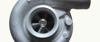
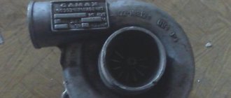
One of the ways to increase the power of a diesel engine is a turbine charging system, its main element is a turbocharger.
It is installed on the discharge manifold and is driven by the energy of exhaust gases. The use of a turbine on KamAZ gives an increase in engine power of about 25%. These trucks use two-row V-shaped power units. Therefore, 2 compressors are installed - each on its own unit. The modern market offers a fairly wide selection of turbochargers for KamAZ vehicles, but this does not mean that you can simply purchase any unit that is suitable for the price - it all depends on the brand of the engine and, very importantly, on its Euro environmental standard.
Currently, on various modifications of KamAZ you can find engines of four environmental classes - from Euro 0 (only on older models) to Euro 3.
Euro 0 class consists of two engines:
— KamAZ 740.10; — KamAZ 7403.
On sale you can find turbochargers only for various modifications of the KamAZ 7403 engine - these are the well-proven TKR7N-1. But the Euro 0 class is gradually being replaced, so the time is very close when such turbochargers simply will not exist.
Euro 1 class includes two popular engines:
— KamAZ 740.11; — KamAZ 740.13.
A large number of turbochargers are available for these engines, including various modifications of TKR7 and K27, as well as foreign units from CZ Strakonice (Czech Republic) and Schwitzer (Germany).
Euro 2 class is one of the most common; four engines correspond to this class:
— KamAZ 740.31-240; — KamAZ 740.30-260; — KamAZ 740.50-360; — KamAZ 740.51-320.
These engines are equipped with the turbochargers already mentioned above in Euro 2 modifications.
The Euro 3 class is by far the highest class of KamAZ engines and includes five units:
— KamAZ 740.60-360; — KamAZ 740.61-320; — KamAZ 740.62-280; — KamAZ 740.63-400; — KamAZ 740.37-400.
Manufacturers of fuel dispensers
OJSC "KAMAZ"
for KamAZ engines TKR7 turbochargers of various modifications (from Euro 0 to Euro 2). These units are available at an affordable price.
NPO "Turbotechnika"
Domestic enterprise (city of Protvino, Moscow region), specializing in the production of turbochargers. Manufactures the most popular TKR-7 units of various modifications.
"TURBO ENGINEERING"
The domestic manufacturer of turbochargers offers popular K-27TI units of modifications from Euro 1 to Euro 3.
OJSC "Borisov Plant of Aggregates" (BZA).
A Belarusian enterprise that, among other things, offers turbochargers similar to TKR7.
CZ Strakonice.
A Czech plant from the city of Strakonice, offering popular turbochargers in our country - analogues of K-27 units. Despite their high quality, they are somewhat more expensive than domestic turbochargers.
Borg Warner Turbosystems.
A German concern offering high-quality turbochargers under the Schwitzer brand.
Why is it better to buy from us:
| We provide a guarantee on all units sold. Our managers will help you decide on the modification you need. |
| No 100% prepayment. Payment after inspection of the goods. |
| Affordable prices and high quality products. Discounts for regular customers. |
| Fast delivery of purchases to the desired city. Delivery to select cities is free. |
To buy you need:
| Call (8552) 78-35-00 and you should clarify: - car model and year of manufacture - unit model, Euro environmental class, power. |
| Send details by email |
| The sale is formalized by signing a purchase and sale agreement. Prepayment is required. |
| Delivery is carried out by transport carriers or by our forces. Before payment, you will be able to inspect and check the unit at the delivery point. After inspection, you make payment and receive the goods. |
Request an offer
_______________________________________________________________________________
Turbocharger of Kamaz-740 engines and its components
Models of turbochargers used on Kamaz vehicle engines In the supercharging systems of Kamaz-740 diesel engines, single-stage turbochargers are used, consisting of a centrifugal compressor and a radial centrifugal turbine. Since the operation of the engine and turbocharger of a Kamaz vehicle is coordinated, it is possible to install a certain type of turbocharger only on the engine for which it is intended. For Kamaz engines 740.31-240, 740.30-260, 740.35-400, 740.37-400, 740.38-360, 740.51-320, 740.50-360, 740.60-360, 740.61-320, 740.62-280 , 740.63-400, 740.65-240 two TKR 7S-6 turbochargers are installed. Two TKR 7S-9 or K27-115 turbochargers are installed on Kamaz 740.11-240, 740.13-260, 740.14-300 engines. Description of the Kamaz-740 gas turbine supercharging and charge air cooling system All Kamaz vehicles, except for versions with engines of models 7403.10, 740.11-240, 740.13-260, 740.14-300, use a charge air cooling system (CAC). The Kamaz-740 gas turbine supercharging and charge air cooling system provides, by using part of the energy of the exhaust gases, the supply of pre-compressed and cooled air to the engine cylinders. This allows you to increase the charge density of the air entering the cylinders and burn a larger amount of fuel in the same working volume, i.e. increase engine liter power.
Rice. 1 — Diagram of the Kamaz-740 gas turbine pressurization and charge air cooling system 1 — charge air cooling heat exchanger: 2 — radiator of the cooling system; 3 - fan; 4 - engine; 5.6-turbocompressors The gas turbine supercharging and charge air cooling system (Fig. 1) of the Kamaz-740 engine consists of two interchangeable turbochargers (TKR) 5 and 6, exhaust and intake manifolds and pipes, a charge air cooling heat exchanger 1 type “air-to-air” ", inlet and outlet pipelines. The air into the centrifugal compressor of the Kamaz-740 turbocharger comes from the air cleaner, is compressed and supplied under pressure to the ONV heat exchanger, and then the cooled air enters the engine. Kamaz-740 turbochargers are installed on the exhaust pipes, one for each row of cylinders. Exhaust manifolds and pipes are made of high-strength cast iron. The gas joints between the mounting flanges of the turbocharger turbine, exhaust pipes and manifolds are sealed with gaskets made of heat-resistant steel. The gas joint between the exhaust manifold and the cylinder head is sealed with a gasket made of asbestos steel sheet edged with a heat-resistant steel tape. Gaskets are disposable parts and must be replaced when the system is overhauled. The exhaust manifolds of the Kamaz-740 turbocharger are bolted to the cylinder heads. To compensate for angular movements that occur during heating, special spherical washers are installed under the heads of the exhaust manifold mounting bolts. The intake manifolds and turbocharger pipes of the KamAZ-740 are made of cast aluminum alloy and are connected to each other using bolts. The joints between the collectors and pipes are sealed with paronite gaskets. The gas turbine charging and charge air cooling system of the Kamaz-740 engine must be sealed. Due to the leakage of the system, exhaust gases or air leak, resulting in a decrease in the performance of the Kamaz-740 turbocharger, which leads to a decrease in engine power. In addition, if the intake tract is not sealed, between the air filter and the turbocharger, abrasive material (sand, dirt) gets into the compressor housing and the engine, which leads to “dust” wear of the compressor wheel blades and parts of the cylinder-piston group and, ultimately, to premature engine failure.
Rice. 2 — Diagram of the Kamaz-740 gas turbine supercharging system (without charge air cooling) 1 — turbochargers; 2 — left exhaust pipe; 3 — left inlet pipe; 4 — left exhaust manifold; 5 — left intake manifold; 6 — connecting pipe; 7 — right intake manifold; 8 — right exhaust manifold; 9 — right exhaust pipe; 10 — right inlet pipe. The bearings of Kamaz-740 turbochargers are lubricated from the engine lubrication system through fluoroplastic tubes with a metal braid. Oil is drained from turbochargers through steel bellows tubes into the engine crankcase. In Fig. Figure 2 shows a gas turbine supercharging system without charge air cooling. The principle of operation of such a system is the same as that presented above, except that the compressed air supplied to the engine cylinders is not cooled. Design of turbochargers used on Kamaz engines
Rice. 3 — Turbocharger TKR 7N-1 1 — bearing; 2 — screen; 3 - compressor housing; 4 — diffuser; 5 - sealing ring; 6 - nut; 7 — oil deflector; 8 — compressor wheel; 9 — oil discharge screen; 10 - cover; 11 — bearing housing; 12 — clamp; 13 — adapter; 14 - gasket; 15 — turbine screen; 16 — turbine wheel with shaft; 17 — turbine housing; 18 - sealing ring. The design of the TKR 7N-1 turbocompressor (Fig. 3) uses an isobaric single-pass turbine housing made of high-strength cast iron and a bronze oscillating-type mono-bushing as a bearing. The rotor of the Kamaz-740 turbocharger consists of a turbine wheel with shaft 16, a compressor wheel 8 and an oil deflector 7, secured to the shaft with a nut 6. The rotor rotates in bearing 1, which is held from axial and radial movements by a clamp 12, which, together with adapter 13, is also an oil supply channel . The compressor rotor and wheel are dynamically balanced with high precision on special balancing machines. In the bearing housing 11, steel covers 10 and an oil discharge screen 9 are installed, which, together with elastic split rings 5, prevents oil from leaking from the cavity of the bearing housing. To reduce heat transfer from the turbine housing to the bearing housing, a cast iron screen 15 and an edged asbestos gasket 14 are installed between them. The compressor housing and the Kamaz-740 turbine housing are attached to the bearing housing using bolts and strips. The M6 compressor housing fastening bolts must be tightened with a torque of 4.9...7.8 Nm (0.5...0.8 kg/cm), and the M8 turbine housing fastening bolts must be tightened with a torque of 23.5...29.4 Nm (2.4... 3.0 kg/cm). The design of the TKR 7S-6 (TKR7S-9) turbocompressor (Figure 4) uses a two-pass turbine housing 7 made of high-strength cast iron. The Kamaz-740 turbocharger rotor consists of a turbine wheel 9 with a shaft 10, a compressor wheel 1, an oil deflector 16 and a bushing 15, secured to the shaft with a nut 19. The rotor rotates in bearings 5, which are floating rotating bushings. Axial movements are limited by thrust bearing 4 installed between bearing housing 3 and cover 2. The bearings are made of bronze.
Rice. 4 — Turbocompressor TKR 7S-6 1 — compressor housing; 2 - cover; 3 — bearing housing; 4 — thrust bearing; 5 - bearing; 6 — retaining ring; 7 — turbine housing; 8 — sealing ring; 9 — turbine wheel; 10 — rotor shaft; 11 — turbine screen; 12, 17 — strips; 13, 18 — bolts; 14 — oil discharge screen; 15 — bushing; 16 — oil deflector; 19 - nut; 20 — compressor wheel; 22 — diffuser; 24 — adapter; 25 — gasket, 21, 23 — sealing ring (rubber). The bearing housing of the Kamaz-740 turbocharger, in order to reduce heat transfer from the turbine to the compressor, is made of a cast iron housing and an aluminum alloy cover. To reduce heat transfer between the turbine housing and the bearing housing, a turbine screen 11 made of heat-resistant steel is installed. An oil discharge screen 14 is installed in the bearing housing, which, together with elastic sealing rings 8, prevents oil leakage from the housing cavity. To eliminate air leaks, a rubber O-ring 21 is installed in the connection “compressor housing - bearing housing”. The turbine and compressor housings are attached to the bearing housing using bolts 13, 18 and strips 12, 17. The tightening torques for the bolts are the same as for TKR 7N- 1. This design allows the housings to be installed at any angle to each other, which in turn facilitates the installation of the TKR on the engine. Turbochargers TKR 7S-6 and TKR 7S-9 differ from each other only in their turbine housings - they have different throughput capacities. Turbochargers K27-115 right and left (designation of the right turbocharger is 399 0023 115-01, left - 399 0023 115-02) have no design differences, they differ only in the rotation of the turbine and compressor housings. The K27-115 turbocharger has a design similar to the TKR 7S-9, and in terms of installation and connection dimensions it is unified with the TKR 7S-9. The turbine housing and the Kamaz-740 compressor housing are attached to the bearing housing using bolts and strips. This design allows the housings to be installed at any angle to each other, which in turn ensures the interchangeability of the left and right turbochargers. Cleaning of the Kamaz-740 centrifugal compressor must be performed in the following sequence: - apply combined marks to the end surfaces of the Kamaz-740 compressor housing and the cover. Unscrew the compressor housing mounting bolts. Remove the compressor housing by lightly hitting the bosses with a hammer. Inspect the rubber O-ring in the groove of the cover. If defects are detected (cuts, loss of elasticity), replace the sealing ring with a new one; — inspect the wheel blades of the Kamaz-740 compressor. If traces of contact with the compressor housing, deformation of the blades or their destruction are detected, the turbocharger must be repaired at a specialized enterprise or replaced; — wash the internal cavity of the compressor housing and the surface of the cover with a rag soaked in diesel fuel. When cleaning the compressor wheel, it is recommended to clean the inter-blade surfaces with a hair brush using diesel fuel; — check the ease of rotation of the Kamaz-740 rotor; jamming of the rotor is not allowed; — before assembly, it is necessary to lubricate the O-ring with engine oil, align the marks, install the compressor housing on the cover disk, tighten the bolts with a torque wrench. Check again that the rotor rotates easily. In extreme axial and radial positions, the rotor wheels should not contact the body parts. Due to the fact that the rotor of the Kamaz-740 turbocharger is balanced with high precision, complete disassembly, repair and maintenance of the supercharging units must be carried out at specialized enterprises that have the necessary equipment, tools, fixtures, instruments and trained personnel. During seasonal maintenance, it is necessary to drain the condensate accumulated in the charge air cooling heat exchanger. Turn the Kamaz-740 charge air cooling heat exchanger upside down in a vertical plane with the pipes down and allow any remaining condensate and oil to drain. Blow along the front of the matrix each row of heat exchange plates between the tubes on each side with a stream of compressed air, preventing their deformation. In case of severe contamination of the heat exchange plates, wash the matrix of the Kamaz-740 charge air cooling heat exchanger under running hot water using a hair brush or by dipping in a bath of hot water. After washing, blow the matrix along the front with compressed air, avoiding deformation of the surfaces of the heat transfer plates. Drying is carried out with a stream of hot air.
_______________________________________________________________________________
_______________________________________________________________________________
_______________________________________________________________________________
- Clutch KamAZ-5320 and its components
- Repair of PGU and Kamaz clutch master cylinder
- Gearbox gearbox KamAZ 141
- Gearbox gearbox KamAZ ZF 16
- Gearbox 152 Kamaz with divider
- Gearbox gearbox 154 Kamaz
- Gearbox Kamaz-4308
- Clutch of a Kamaz-4308 car
- Clutch and gearbox KamAZ-65115
- Disassembly and assembly of Kamaz-4310, 55111, 43118 gearboxes
_______________________________________________________________________________
- Cylinder block, head and valves Kamaz-740
- Fuel system of Kamaz-740 diesel engine
- Adjustments and repairs of fuel injection pump Kamaz-740
- Drive axles of the Kamaz-4310 vehicle
- Repair of Kamaz drive axle gearbox
- Rear axle KamAZ-4308
- Axles and suspensions of Kamaz-65115 dump trucks
- Installation of Kamaz cardan shafts and axles
- Repair of Kamaz vehicle transfer case
- Kamaz power steering - adjustments and repairs
- Repair of Kamaz steering gear parts
- Steering parts Kamaz-4308
- Parts of the brake system Kamaz-4308
- Brake system and brake drive Kamaz
- Repair of brake valves and Kamaz compressor
- Suspension Kamaz-4310, 55111, 43118 and their parts
- Frame and suspension of the Kamaz-4308 car
- Cabin details and platform KamAZ-65115
- Cabin components Kamaz-4308
- Platform mechanism of Kamaz vehicles
- Klintsy KS 65719-5K truck crane based on KamAZ-6522 chassis
- Truck crane KC-35719-7-02 based on Kamaz-43118 chassis
- Truck crane Galichanin KC-55713-1K based on KamAZ-65115 6x4
- Ivanovets KS-45717K-1/1R truck crane based on KamAZ-65115 chassis
- Ivanovets KS-3577-3/4 truck crane on KamAZ-43253 4x2 chassis
Diesel engines of trucks and tractors. Spare parts, adjustments and repairs.
________________________________________________________________
___________________________________________________________________________
The design of the Kamaz-740 diesel turbocharger
Models of turbochargers used on Kamaz vehicle engines In the supercharging systems of Kamaz-740 diesel engines, single-stage turbochargers are used, consisting of a centrifugal compressor and a radial centrifugal turbine. Since the operation of the engine and turbocharger is coordinated, it is possible to install a certain type of turbocharger only on the engine for which it is intended. For Kamaz engines 740.31-240, 740.30-260, 740.35-400, 740.37-400, 740.38-360, 740.51-320, 740.50-360, 740.60-360, 740.61-320, 740.62-280 , 740.63-400, 740.65-240 two TKR 7S-6 turbochargers are installed. Two TKR 7S-9 or K27-115 turbochargers are installed on Kamaz 740.11-240, 740.13-260, 740.14-300 engines. Description of the gas turbine supercharging and charge air cooling system of the Kamaz-740 engine All vehicles, except those with engines of models 7403.10, 740.11-240, 740.13-260, 740.14-300, use a charge air cooling system (CAC). The gas turbine supercharging and charge air cooling system provides, by using part of the energy of the exhaust gases, the supply of pre-compressed and cooled air to the engine cylinders. This allows you to increase the charge density of the air entering the cylinders and burn a larger amount of fuel in the same working volume, i.e. increase engine liter power. Rice. 1 — Diagram of the Kamaz-740 gas turbine pressurization and charge air cooling system 1 — charge air cooling heat exchanger: 2 — radiator of the cooling system; 3 - fan; 4 - engine; 5.6-turbocompressors The gas turbine supercharging and charge air cooling system (Fig. 1) consists of two interchangeable turbocompressors (TCR) 5 and 6, exhaust and intake manifolds and pipes, a charge air cooling heat exchanger of type 1 “air-to-air”, supply and outlet pipelines. The air into the centrifugal compressor of the Kamaz-740 turbocharger comes from the air cleaner, is compressed and supplied under pressure to the ONV heat exchanger, and then the cooled air enters the engine. Turbochargers are installed on the exhaust pipes, one for each bank of cylinders. Exhaust manifolds and pipes are made of high-strength cast iron. The gas joints between the mounting flanges of the turbocharger turbine, exhaust pipes and manifolds are sealed with gaskets made of heat-resistant steel. The gas joint between the exhaust manifold and the cylinder head is sealed with a gasket made of asbestos steel sheet edged with a heat-resistant steel tape. Gaskets are disposable parts and must be replaced when the system is overhauled. The exhaust manifolds of the Kamaz-740 turbocharger are bolted to the cylinder heads. To compensate for angular movements that occur during heating, special spherical washers are installed under the heads of the exhaust manifold mounting bolts. The intake manifolds and turbocharger pipes are made of cast aluminum alloy and are connected to each other using bolts. The joints between the collectors and pipes are sealed with paronite gaskets. The gas turbine charging and charge air cooling system must be sealed. Due to the leakage of the system, exhaust gases or air leak, resulting in reduced performance of the turbocharger, which leads to a decrease in engine power. In addition, if the intake tract is not sealed, between the air filter and the turbocharger, abrasive material (sand, dirt) gets into the compressor housing and the engine, which leads to “dust” wear of the compressor wheel blades and parts of the cylinder-piston group and, ultimately, to premature engine failure. Rice. 2 — Diagram of the Kamaz-740 gas turbine supercharging system (without charge air cooling) 1 — turbochargers; 2 — left exhaust pipe; 3 — left inlet pipe; 4 — left exhaust manifold; 5 — left intake manifold; 6 — connecting pipe; 7 — right intake manifold; 8 — right exhaust manifold; 9 — right exhaust pipe; 10 — right inlet pipe. The bearings of Kamaz-740 turbochargers are lubricated from the engine lubrication system through fluoroplastic tubes with a metal braid. Oil is drained from turbochargers through steel bellows tubes into the engine crankcase. In Fig. Figure 2 shows a gas turbine supercharging system without charge air cooling. The principle of operation of such a system is the same as that presented above, except that the compressed air supplied to the engine cylinders is not cooled. Design of turbochargers used on Kamaz-740 engines Fig. 3 — Turbocharger TKR 7N-1 1 — bearing; 2 — screen; 3 - compressor housing; 4 — diffuser; 5 - sealing ring; 6 - nut; 7 — oil deflector; 8 — compressor wheel; 9 — oil discharge screen; 10 - cover; 11 — bearing housing; 12 — clamp; 13 — adapter; 14 - gasket; 15 — turbine screen; 16 — turbine wheel with shaft; 17 — turbine housing; 18 - sealing ring. The design of the TKR 7N-1 turbocompressor (Fig. 3) uses an isobaric single-pass turbine housing made of high-strength cast iron and a bronze oscillating-type mono-bushing as a bearing. The turbocharger rotor consists of a turbine wheel with a shaft 16, a compressor wheel 8 and an oil deflector 7, secured to the shaft with a nut 6. The rotor rotates in a bearing 1, which is held from axial and radial movements by a retainer 12, which, together with the adapter 13, is also an oil supply channel. The compressor rotor and wheel are dynamically balanced with high precision on special balancing machines. In the bearing housing 11, steel covers 10 and an oil discharge screen 9 are installed, which, together with elastic split rings 5, prevents oil from leaking from the cavity of the bearing housing. To reduce heat transfer from the turbine housing to the bearing housing, a cast iron screen 15 and an edged asbestos gasket 14 are installed between them. The compressor housing and the Kamaz-740 turbine housing are attached to the bearing housing using bolts and strips. The M6 compressor housing fastening bolts must be tightened with a torque of 4.9...7.8 Nm (0.5...0.8 kg/cm), and the M8 turbine housing fastening bolts must be tightened with a torque of 23.5...29.4 Nm (2.4... 3.0 kg/cm). The design of the TKR 7S-6 (TKR7S-9) turbocompressor (Figure 4) uses a two-pass turbine housing 7 made of high-strength cast iron. The turbocharger rotor consists of a turbine wheel 9 with a shaft 10, a compressor wheel 1, an oil deflector 16 and a bushing 15, secured to the shaft with a nut 19. The rotor rotates in bearings 5, which are floating rotating bushings. Axial movements are limited by thrust bearing 4 installed between bearing housing 3 and cover 2. The bearings are made of bronze. Rice. 4 — Turbocompressor TKR 7S-6 1 — compressor housing; 2 - cover; 3 — bearing housing; 4 — thrust bearing; 5 - bearing; 6 — retaining ring; 7 — turbine housing; 8 — sealing ring; 9 — turbine wheel; 10 — rotor shaft; 11 — turbine screen; 12, 17 — strips; 13, 18 — bolts; 14 — oil discharge screen; 15 — bushing; 16 — oil deflector; 19 - nut; 20 — compressor wheel; 22 — diffuser; 24 — adapter; 25 — gasket, 21, 23 — sealing ring (rubber). The turbocharger bearing housing, in order to reduce heat transfer from the turbine to the compressor, is made of a cast iron housing and an aluminum alloy cover. To reduce heat transfer between the turbine housing and the bearing housing, a turbine screen 11 made of heat-resistant steel is installed. An oil discharge screen 14 is installed in the bearing housing, which, together with elastic sealing rings 8, prevents oil leakage from the housing cavity. To eliminate air leaks, a rubber O-ring 21 is installed in the connection “compressor housing - bearing housing”. The turbine and compressor housings are attached to the bearing housing using bolts 13, 18 and strips 12, 17. The tightening torques for the bolts are the same as for TKR 7N- 1. This design allows the housings to be installed at any angle to each other, which in turn facilitates the installation of the TKR on the engine. Turbochargers TKR 7S-6 and TKR 7S-9 differ from each other only in their turbine housings - they have different throughput capacities. Turbochargers K27-115 right and left (designation of the right turbocharger is 399 0023 115-01, left - 399 0023 115-02) have no design differences, they differ only in the rotation of the turbine and compressor housings. The K27-115 turbocharger has a design similar to the TKR 7S-9, and in terms of installation and connection dimensions it is unified with the TKR 7S-9. The turbine housing and compressor housing are attached to the bearing housing using bolts and strips. This design allows the housings to be installed at any angle to each other, which in turn ensures the interchangeability of the left and right turbochargers. Cleaning of the Kamaz-740 centrifugal compressor must be performed in the following sequence: - apply combined marks to the end surfaces of the housing and cover. Unscrew the compressor housing mounting bolts. Remove the compressor housing by lightly hitting the bosses with a hammer. Inspect the rubber O-ring in the groove of the cover. If defects are detected (cuts, loss of elasticity), replace the sealing ring with a new one; — inspect the compressor wheel blades. If traces of contact with the compressor housing, deformation of the blades or their destruction are detected, the turbocharger must be repaired at a specialized enterprise or replaced; — wash the internal cavity of the compressor housing and the surface of the cover with a rag soaked in diesel fuel. When cleaning the compressor wheel, it is recommended to clean the inter-blade surfaces with a hair brush using diesel fuel; — check the ease of rotation of the rotor; jamming of the rotor is not allowed; — before assembly, it is necessary to lubricate the O-ring with engine oil, align the marks, install the compressor housing on the cover disk, tighten the bolts with a torque wrench. Check again that the rotor rotates easily. In extreme axial and radial positions, the rotor wheels should not contact the body parts. Due to the fact that the rotor of the Kamaz-740 turbocharger is balanced with high precision, complete disassembly, repair and maintenance of the supercharging units must be carried out at specialized enterprises that have the necessary equipment, tools, fixtures, devices and trained personnel. During seasonal maintenance, it is necessary to drain the condensate accumulated in the charge air cooling heat exchanger. Turn the charge air cooling heat exchanger upside down in a vertical plane with the pipes downwards and allow any remaining condensate and oil to drain out. Blow along the front of the matrix each row of heat exchange plates between the tubes on each side with a stream of compressed air, preventing their deformation. In case of severe contamination of the heat exchange plates, wash the matrix of the charge air cooling heat exchanger under running hot water using a hair brush or by dipping in a hot water bath. After washing, blow the matrix along the front with compressed air, avoiding deformation of the surfaces of the heat transfer plates. Drying is carried out with a stream of hot air.
___________________________________________________________________
___________________________________________________________________
- Injection pump D-245 - design and adjustments
- Timing belt and valves D-245
- Engine lubrication system D-245
- Fuel system parts D-245
- Operations for adjusting YaMZ-236
- Operations for disassembling and installing fuel injection pump YaMZ-236
- Cooling system and lubrication system YaMZ-238
- Fuel injection pump YaMZ-238
- Characteristics of Cummins ISBe, ISLe, ISB, QSB
___________________________________________________________________
___________________________________________________________________
- Repair and replacement of Cummins ISBe, ISLe, ISB crankshaft
- Cummins ISBe, ISLe, QSB cylinder block repair
- Connecting rod and piston group Cummins ISBe, ISLe, ISB
- Diesel cooling system ISF 2.8
- ISF 2.8 diesel cylinder block and pistons
- Cummins ISF 3.8 Fuel System Components
- Cummins 3.8 engine lubrication system
- Cummins ISF 3.8 Cooling System
- Cylinder head YaMZ-7511
- YaMZ-7511 cylinder block
- Diesel crankshaft YaMZ-7511