Payment for goods and downloading of the book in electronic form (PDF format) is made on the website.
To do this, you need to find the book you are interested in and click on the “Buy” button. The price of the book is indicated on the button.
For convenience, the price on the website for residents of Russia, Belarus and Kazakhstan is presented in rubles.
For residents of Ukraine in hryvnias, and for all other countries - dollars.
After clicking on the “BUY” button, a payment window will open where you can select a payment system with which you can pay for the selected book using any bank card (Visa, MasterCard, MIR, etc.)
When you click on the “Pay by bank card” button, the Portmone payment system will open, which is the easiest way to make a payment.
In addition, the website offers four payment systems for payment:
- Yandex (payment from any bank cards, Yandex Money account, QIWI Wallet, terminals, etc.);
- Portmone (payment from any bank cards, Portmone account);
- PayPal (payment from any bank cards, PayPal account);
- WebMoney (payment from any bank cards, payment from WebMoney wallets).
Payment via Yandex Cashier
After selecting payment via Yandex, the Yandex Cashier payment system will launch, where you need to select a convenient payment method (bank card, QIWI, Yandex Money account, etc.)
After specifying payment details and confirming payment, payment for the goods will occur.
If you have a bank card in a currency other than the ruble, then the money will be debited from the card at the rate of the Central Bank of Russia at the time of the purchase.
This payment method is optimal for residents of Russia, Kazakhstan and Belarus.
Official website of the Yandex Kassa payment system https://kassa.yandex.ru
Payment via Portmone
After selecting payment through Portmone, the payment system will launch, where you need to select the payment method: bank card or Portmone account.
The price in the Portmone payment system is converted into dollars at the exchange rate of the Central Bank of the country where you are located.
If you have a bank card in a currency other than the dollar, then the money will be debited from the card at the rate of the Central Bank of your country at the time of the purchase.
After specifying payment details and confirming payment, payment for the goods will occur.
Official website of the Portmone payment system https://www.portmone.com
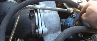
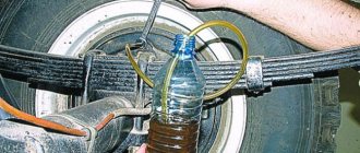
Air distributor KamAZ
With a single-wire drive, the connecting line is connected to terminal I. The supplied compressed air bends the edges of cuff 1 of piston 2 and passes into the trailer cylinder through terminal IV. The trailer chambers with outlet III are connected to the atmosphere through an open exhaust valve 5, a hollow valve sleeve 6 and atmospheric outlet II.
When the pressure in the line drops (braking), the pressure in terminal I also decreases, and piston 2, overcoming the resistance of spring 9, moves downward under the influence of pressure in terminal IV. Rod 3 and piston 4 move with it. In this case, the outlet valve 5 closes, and the inlet valve 7 opens, and compressed air from the trailer cylinder through terminal IV flows to terminal III and then to the trailer chambers. The tracking action is carried out by piston 4.
If the pressure in the connecting line increases (deceleration occurs), the process occurs in the reverse order. Pistons 2 and 4 move upward, inlet valve 7 closes, then exhaust valve 5 opens, connecting port III (brake chambers) to atmospheric port II.
In the case of a two-wire drive, the supply line is connected to terminal I, and the control (brake) line is connected to terminal V. The compressed air supplied through the supply line through cuff 1 of piston 2 enters the trailer cylinder through terminal IV.
When braking, compressed air supplied to terminal V acts on piston 11 and moves it down. Compressed air from the trailer cylinder enters the brake chambers connected to terminal III. The tracking action is carried out in this case by piston II.
The air distributor has a built-in equalizing valve 10. With a single-line drive, when the air pressure supplied to terminal I does not exceed 5.2 kgf/cm2, valve 10 does not work. In the case of a two-wire drive, when compressed air with a nominal pressure of 7 kgf/cm2 is supplied to terminal I, valve 10 opens and the pressure above and below piston 2 is equalized.
In the event of an emergency drop in pressure in the supply line, valve 10 initially remains open, and the pressure in the trailer cylinder also decreases. If the pressure in the line drops below 5.3 kgf/cm2, then valve 10 closes, and the pressure in the sight cylinder and above piston 2 does not change. With a further decrease in pressure in the line, the air distributor brakes the trailer in the same way as with a single-line drive.
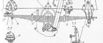
Rice. 127. KamAZ air distributor:
I - output to the connecting or supply line; II - release into the atmosphere; III - output to the brake chambers; IV - output to the air balloon; V - output to the brake control line;
Payment via PayPal
After selecting payment via PayPal, the PayPal payment system will launch, where you need to select the payment method: bank card or PayPal account.
If you already have a PayPal account, then you need to log into it and make a payment.
If you do not have a PayPal account and you want to pay using a bank card via PayPal, you need to click on the “Create an Account” button - shown with an arrow in the picture.
PayPal will then prompt you to select your country and provide your credit card information.
After specifying the information required to make the payment, you must click on the “Pay Now” button.
Official website of the PayPal payment system https://www.paypal.com
_______________________________________________________________________________
Brake system and brake drive of Kamaz vehicles
Brake system of Kamaz vehicles
The braking system of Kamaz-5320 vehicles consists of four autonomous braking systems: service, spare, parking and auxiliary. Although Kamaz brake systems have common elements, they operate independently and provide high braking efficiency in any operating conditions. In addition, the Kamaz vehicle is equipped with an emergency brake release drive, which makes it possible to resume the movement of the vehicle (road train) when it is automatically braked due to a compressed air leak, an alarm and control devices that allow monitoring the operation of the pneumatic drive. The Kamaz-5320 braking system is designed to reduce the speed of the vehicle or stop it completely. The brakes of the Kamaz-5320 service brake system are installed on all six wheels of the vehicle. The drive of the working brake system of KamAZ-5320 is a pneumatic dual-circuit one; it operates separately the brake mechanisms of the front axle and the rear bogie of the vehicle. The drive is controlled by a foot pedal, mechanically connected to the brake valve. The executive bodies of the drive of the working brake system of KamAZ-5320 are the brake chambers. The Kamaz-5320 spare brake system is designed to smoothly reduce the speed or stop a moving vehicle in the event of a complete or partial failure of the working system. The Kamaz parking brake system provides braking for a stationary vehicle on a horizontal section, as well as on a slope and in the absence of a driver. The parking brake system on Kamaz vehicles is designed as a single unit with the spare one, and to activate it, the hand valve handle should be set to the extreme (upper) fixed position. Thus, the Kamaz brakes of the rear bogie are common to the working, spare and parking brake systems, and the latter two also have a common pneumatic drive. The Kamaz brake auxiliary system serves to reduce the load and temperature of the brake mechanisms of the service brake system. The auxiliary braking system on Kamaz vehicles is an engine retarder, when activated, the engine exhaust pipes are blocked and the fuel supply is turned off. The Kamaz emergency brake release system is designed to release spring energy accumulators when they are automatically activated and the vehicle stops due to a compressed air leak in the drive. The drive of the Kamaz emergency brake release system is duplicated: in addition to the pneumatic drive, there are emergency brake release screws in each of the four spring energy accumulators, which allows the latter to be released mechanically. The Kamaz alarm and control system consists of two parts: - Light and acoustic signaling about the operation of brake systems and their drives. At various points of the Kamaz pneumatic drive there are built-in pneumatic-electric sensors, which, when any braking system, except for the auxiliary one, closes the circuits of the electric brake light lamps. Pressure drop sensors are installed in the drive receivers and, if there is insufficient pressure in the latter, they close the circuits of the signal lamps located on the vehicle's instrument panel, as well as the sound signal (buzzer) circuit. — Valves of control terminals, with the help of which the technical condition of the Kamaz pneumatic brake drive is diagnosed, as well as (if necessary) the selection of compressed air.
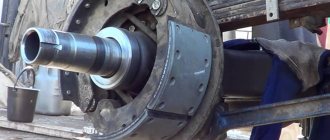
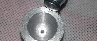
Tractor vehicles are also equipped with a set of pneumatic devices for actuating the brake mechanisms of a Kamaz trailer (semi-trailer) with a single-wire and double-wire drive. The presence of such a drive on tractors ensures their aggregation with any trailers (semi-trailers) that have a pneumatic drive of the brake mechanisms. Kamaz brakes (Fig. 1) are installed on all six wheels, the main unit of the brake mechanism is mounted on caliper 2, rigidly connected to the axle flange. Fig.1. Kamaz 1 brake - pad axis; 2 — caliper; 3 — shield; 4 - axle nut; 5 — pad axle lining; 6 — block axis pin; 7 — brake pad; 8 - spring; 9 — friction lining; 10-bracket for expanding fist; 11 — roller axis; 12 — expansion fist; 13 - roller; 14 — adjusting lever Two brake pads 7 with friction linings 9 attached to them, made along a crescent-shaped profile in accordance with the nature of their wear, are freely supported on the eccentrics of the axles 1, fixed in the caliper. The axes of the shoes with eccentric supporting surfaces allow the shoes to be correctly centered relative to the brake drum when assembling the brake mechanisms. The Kamaz-5320 brake drum is attached to the wheel hub with five bolts. When braking, the KamAZ-5320 pads are moved apart by an S-shaped fist 12 and pressed against the inner surface of the drum. Between the expanding fist 12 and the pads 7, rollers 13 are installed, which reduce friction and improve braking efficiency. The pads are returned to the released state by four release springs 8. The expansion fist 12 rotates in the bracket 10, bolted to the caliper. The brake chamber is installed on this bracket. At the end of the expanding fist shaft there is an adjusting lever 14 of the worm type, connected to the Kamaz-5320 brake chamber rod using a fork and a pin. A shield bolted to the caliper protects the brake mechanism from dirt. The Kamaz adjusting brake lever (ratchet) is designed to reduce the gap between the pads and the brake drum, which increases due to wear of the friction linings. The device of the adjusting lever (ratchet) KamAZ is shown in Fig. 2. The adjusting lever has a steel body 6 with a sleeve 7. Fig.2. Adjusting brake lever (ratchet) KamAZ 1 - cover; 2 - rivet; 3 - gear wheel; 4 - plug; 5 - worm; 6 — body; 7 - bushing; 8- locking bolt; 9 — clamp spring; 10 — retainer ball; 11 - worm axis; 12 - oiler In the body of the Kamaz ratchet there is a worm gear 3 with splined holes for installation on the expansion fist and worm 5 with an axis 11 pressed into it. To fix the worm axis there is a locking device, the ball 10 of which enters the holes on the worm axis 11 under the action spring 9 resting on locking bolt 8. The gear wheel is kept from falling out by covers 1 attached to the lever body 6. When the axle is turned (by the square end), the worm turns wheel 3, and the expansion fist turns with it, pushing the pads apart and reducing the gap between the pads and the brake drum. When braking, the adjusting brake lever (ratchet) of the Kamaz vehicle is turned by the brake chamber rod. Before adjusting the gap, lock bolt 8 must be loosened one or two turns; after adjustment, tighten the bolt securely. Adjusting Kamaz brakes Two adjustments are made in Kamaz brakes - partial and complete. Partial adjustment of Kamaz brakes is carried out during operation and is aimed at restoring the normal gap between the shoe linings and the brake drum. The need to adjust the Kamaz brakes is judged by the output of the brake chamber rods, which should be 20mm when you press the brake pedal. The required stroke value is set using a worm pair of the adjusting lever. When adjusting, the brake of the Kamaz vehicle should be cold, the parking brake should be released, the locking bolt 8 should be loosened by one or two turns and securely tightened again. To obtain equal braking efficiency for the right and left wheels, the output of the rods of the right and left brake chambers on each axle must be the same. Full adjustment of Kamaz brakes is carried out after disassembling them (replacing linings or pads). The purpose of this adjustment is to position the shoes correctly relative to the drum. Kamaz brakes are adjusted using the eccentric axles of the pads and the adjusting lever. The brake is considered to be adjusted correctly if the gap between the lining and the brake drum, measured with a feeler gauge through the hatch in the support disk at a distance of 30 mm from the edge of the lining in the upper and lower parts, is within 0.2 ... 0.4 mm, and the feeler gauge is 0.1 mm thick mm does not extend along the entire width of the block. Kamaz brake drive Schematic diagrams of the Kamaz brake drive are shown in Fig. 3. The source of compressed air in the drive is compressor 9. The compressor, pressure regulator 11, fuse 12 against condensate freezing, condensation receiver 20 constitute the supply part of the drive, from which purified compressed air at a given pressure is supplied in the required quantity to the remaining parts of the pneumatic brake drive and to other consumers of compressed air. The Kamaz-5320 pneumatic brake drive is divided into autonomous circuits, separated from each other by safety valves. Each circuit operates independently of other circuits, including when faults occur. The Kamaz pneumatic brake drive consists of five circuits, separated by one double and one triple safety valve.
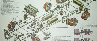
Rice. 3. Diagram of the pneumatic drive of the brake mechanisms of the Kamaz 5320 A vehicle - control output of circuit IV; B, E - valves of control terminals of the third circuit; C - control output of circuit I; D - control output of circuit II; N — brake control line of a two-wire drive; P — connecting line of a single-wire drive; K - line supplying a two-wire drive; 1 — brake chambers type 24; 2 — parking brake system control valve; 3 — emergency brake release valve for the parking brake system; 4 — auxiliary brake system control valve; 5 — two-pointer pressure gauge; 6 — control lamps and sound signaling device; 7 — control valve; 8 — pressure limitation valve; 9 - compressor; 10 — pneumatic cylinder for driving the engine stop lever; 11 — pressure regulator; 12 - anti-freeze fuse; 13 — double safety valve; 14 — sensor for turning on the solenoid valve of the trailer brake mechanism; 15 — rechargeable batteries; 16 — two-section brake valve; 17 — triple safety valve; 18 — pressure drop sensor in the receiver; 19 — condensate drain valves; 20 — condensing receiver; 21 — air bleed valve; 22 — receivers of circuit II; 23 — pneumatic cylinder for the auxiliary brake system flap drive; 24, 25 — receivers of circuits I and III; 26 — brake chambers of type 20×20; 27 — sensor for turning on the warning lamp of the parking brake system; 28 — energy accumulators; 29 — accelerator valve; 30 — automatic brake force regulator; 31 — trailer brake control valve with a two-wire drive; 32 — two-line valve; 33 — sensor for turning on the brake signal; 34 — trailer brake control valve with a single-wire drive; 35 — single safety valve; 36 — rear lights; 37 — isolation valves; 38, 39 — connection heads type A and type “Palm”
Fig.4. Diagram of the pneumatic drive of the brakes of Kamaz-65115 vehicles 1 - water separator; 2 - compressor; 3 - cooler; 4 - four-circuit safety valve; 5 - automatic brake force regulator; 6 — pressure regulator; 7 - brake signal switch; 8 - brake valve; 9 — pneumatic cylinders for the flap drive of the auxiliary brake system mechanism; 10 — parking brake system control valve; 11 - proportional valve; 12 - pneumatic cylinder for driving the engine stop lever; 13 — auxiliary brake system control valve; 14 - pressure gauge; 15- brake chambers type 30/30; 16 - receiver circuit 1Y; 17 — receivers of circuit 11; 18 — condensate drain valve; 19 — brake chambers type 20/20; 20.24 - accelerator valves; 21 - two-line bypass valve; 26 switch for the parking brake system warning lamp; 23 — receiver of circuit III; 25 — receiver of circuit I; 26 — switch for warning lamp for air pressure drop in circuit III; 27 — emergency brake release valve Circuit I of the service brake drive of the Kamaz front axle consists of part of a triple safety valve 17; receiver 24 with a capacity of 20 liters with a condensate drain valve and pressure drop sensor 18 in the receiver, part of a two-pointer pressure gauge 5; lower section of a two-section brake valve 16; valve 7 control terminal (C); pressure limit valve 8; two brake chambers 1; brake mechanisms of the front axle of the tractor; pipelines and hoses between these devices. In addition, the drive circuit for the service brakes of the Kamaz front axle includes a pipeline from the lower section of the brake valve 16 to valve 31 for controlling the brake systems of a trailer with a two-wire drive. Circuit II of the service brake drive of the rear Kamaz truck consists of a part of the triple safety valve 17; 22 receivers with a total capacity of 40 liters with condensate drain valves 19 and pressure drop sensor 18 in the receiver; parts of a two-pointer pressure gauge 5; the upper section of the two-section brake valve 16; control output valve (D) of the automatic brake force regulator 30 with an elastic element; four brake chambers 26; brake mechanisms of the rear bogie (intermediate and rear axles); pipelines and hoses between these devices. The drive circuit for the service brakes of the rear Kamaz truck also includes a pipeline from the upper section of the brake valve 16 to the brake control valve 31 with a two-wire drive. Circuit III of the drive mechanisms of the spare and parking brake systems of Kamaz, as well as the combined drive of the trailer (semi-trailer) brakes, consists of a part of the double safety valve 13; two receivers 25 with a total capacity of 40 liters with a condensate drain valve 19 and a pressure drop sensor 18 in the receivers; two valves 7 control output (B and E) of manual brake valve 2; accelerator valve 29; parts of a two-line bypass valve 32; four spring energy accumulators 28 brake chambers; sensor 27 for pressure drop in the line of spring energy accumulators; valve 31 for controlling the brake mechanisms of a trailer with a two-wire drive; single safety valve 35; valve 34 for controlling the brake mechanisms of a trailer with a single-wire drive; three isolation valves 37 three connection heads; heads 38 type A for a single-wire drive of trailer brakes and two heads 39 of type “Palm” for a two-wire drive of trailer brakes; pneumoelectric sensor 33 of the “stop light”, pipelines and hoses between these devices. It should be noted that the pneumoelectric sensor 33 in the circuit is installed in such a way that it ensures that the brake light lamps turn on when the vehicle is braking not only by the spare (parking) brake system, but also by the working one, and also in the event of failure of one of the circuits of the latter . Circuit IV of the drive of the auxiliary brake system of Kamaz and other consumers does not have its own receiver and consists of a part of a double safety valve 13; pneumatic valve 4; two cylinders 23 damper drives; cylinder 10 of the engine stop lever drive; pneumoelectric sensor 14; pipelines and hoses between these devices. From circuit IV of the drive mechanisms of the Kamaz auxiliary brake system, compressed air is supplied to additional (non-brake) consumers; pneumatic signal, pneumohydraulic clutch booster, control of transmission units, etc. Circuit V of the Kamaz emergency brake release drive does not have its own receiver and actuators. It consists of a triple safety valve part 17; pneumatic valve 4; parts of a two-line bypass valve 32; pipelines and hoses connecting the devices. The pneumatic brake actuators of the Kamaz tractor and trailer are connected by three lines: the single-wire drive line, the supply and control (brake) lines of the two-wire drive. On truck tractors, connecting heads 38 and 39 are located at the ends of three flexible hoses of the said lines, mounted on a support rod. On flatbed vehicles, heads 38 and 39 are mounted on the rear cross member of the frame. To improve moisture separation in the supply part of the brake drive KamAZ 53212, 53213 in the compressor-pressure regulator section, a moisture separator is additionally provided, installed on the first cross member of the vehicle in the intensive airflow zone. For the same purpose, on all models of the Kamaz vehicle, a condensation receiver with a capacity of 20 liters is provided in the section against freezing - protective valves. The Kamaz 55111 dump truck does not have trailer brake control equipment, disconnect valves, or connecting heads. To monitor the operation of the Kamaz pneumatic brake drive and timely signal about its condition and emerging malfunctions in the cockpit, there are five warning lights on the instrument panel, a two-pointer pressure gauge showing the compressed air pressure in the receivers of two circuits (I and II) of the pneumatic drive of the service brake system, and a buzzer signaling an emergency drop in compressed air pressure in the receivers of any brake circuit. Kamaz auxiliary brake system mechanism Fig.5. Mechanism of the auxiliary brake system Kamaz 1 - housing; 2 — rotary lever; 3 - damper; 4 - shaft In the exhaust pipes of the muffler there is a housing 1 and a damper 3 mounted on shaft 4. A rotary lever 2 connected to the pneumatic cylinder rod is also attached to the damper shaft. Lever 2 and the associated damper 3 have two positions. The internal cavity of the body is spherical. When the auxiliary brake system is turned off, damper 3 is installed along the flow of exhaust gases, and when turned on, it is perpendicular to the flow, creating a certain back pressure in the exhaust manifolds. At the same time, the fuel supply is stopped. The engine starts operating in compressor mode.
_______________________________________________________________________________
_______________________________________________________________________________
_______________________________________________________________________________
- Clutch KamAZ-5320 and its components
- Repair of PGU and Kamaz clutch master cylinder
- Gearbox gearbox KamAZ 141
- Gearbox gearbox KamAZ ZF 16
- Gearbox 152 Kamaz with divider
- Gearbox gearbox 154 Kamaz
- Gearbox Kamaz-4308
- Clutch of a Kamaz-4308 car
- Clutch and gearbox KamAZ-65115
- Disassembly and assembly of Kamaz-4310, 55111, 43118 gearboxes
_______________________________________________________________________________
- Cylinder block, head and valves Kamaz-740
- Fuel system of Kamaz-740 diesel engine
- Adjustments and repairs of fuel injection pump Kamaz-740
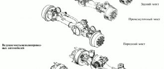
- Drive axles of the Kamaz-4310 vehicle
- Repair of Kamaz drive axle gearbox
- Rear axle KamAZ-4308
- Axles and suspensions of Kamaz-65115 dump trucks
- Installation of Kamaz cardan shafts and axles
- Repair of Kamaz vehicle transfer case
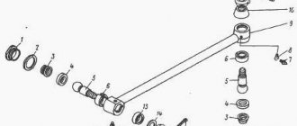
- Kamaz power steering - adjustments and repairs
- Repair of Kamaz steering gear parts
- Steering parts Kamaz-4308
- Parts of the brake system Kamaz-4308
- Brake system and brake drive Kamaz
- Repair of brake valves and Kamaz compressor
- Suspension Kamaz-4310, 55111, 43118 and their parts
- Frame and suspension of the Kamaz-4308 car
- Cabin details and platform KamAZ-65115
- Cabin components Kamaz-4308
- Platform mechanism of Kamaz vehicles
- Klintsy KS 65719-5K truck crane based on KamAZ-6522 chassis
- Truck crane KC-35719-7-02 based on Kamaz-43118 chassis
- Truck crane Galichanin KC-55713-1K based on KamAZ-65115 6x4
- Ivanovets KS-45717K-1/1R truck crane based on KamAZ-65115 chassis
- Ivanovets KS-3577-3/4 truck crane on KamAZ-43253 4x2 chassis
Payment via WebMoney
After selecting payment via WebMoney, the payment system will launch, where you need to select the payment method: bank card or WebMoney wallet.
If you already have a WebMoney wallet, then you need to log into it and make a payment.
If you do not have a WebMoney wallet and you want to pay in another way, you need to select any of the methods that WebMoney offers and make the payment
After specifying payment details and confirming payment, payment for the goods will occur.
Official website of the WebMoney payment system https://www.webmoney.ru/
Circuit III
This is the circuit of the parking, spare brake systems and the combined drive of the brake mechanisms of the semi-trailer (trailer). It consists of:
- double safety valve,
- two receivers with a total capacity of 40 liters, a pressure sensor and a condensate drain valve,
- two control valves of the manual brake valve,
- relay valve,
- four spring energy accumulators of brake chambers with a pressure sensor,
- parts of a two-way bypass valve,
- control valve with two-wire drive of the trailer brake system,
- single safety valve,
- trailer brake control valve with single-line actuator,
- type “A” heads for a single-wire drive and two “Palm” heads for a two-wire drive for trailer brakes,
- three isolation valves, three connection heads,
- pneumoelectric brake light sensor,
- two-wire drive of trailer brakes,
- hoses and pipelines.
Downloading a book
After successfully completing the payment (by any method) and returning to the KrutilVertel store from the payment system website, you will be taken to the successful payment page:
On this page you need to indicate your e-mail, where access to download the book will be sent.
If you are already registered on our website, then simply follow the link to your personal account.
The book you purchased will be in your personal account, from where you can always download it.
Please note that after making the payment, you need to return back from the payment system website to the KrutilVertel website.
If for some reason you did not return back to the site and closed the payment system tab with a message about the successful completion of the payment, please let us know - we will send you a letter indicating access to download the book.
Work principles
The diagram of the KamAZ-5320 brake system should begin to be considered from the principles of operation. After pressing its pedal, pressure is transferred to the amplifier. The last element further affects the main cylinder. The cylinder piston system transfers the resulting energy to move the pads to the truck's discs.
It should be noted that the brake mechanisms are controlled by pressing the brake pedal. Due to this, fluid pressure is created. It is this factor that starts the stopping process. After its final completion, the return spring is activated, so the pedal goes to the inactive position. The piston of the main cylinder also returns to the reverse position. Brake pads provide the necessary degree of lag between the main parts of the springs and the drums.
Additionally, it is important to mention the productivity of the KamAZ-5320 braking system, which meets high requirements due to the inclusion of individual devices to improve safety.
Problems when paying with bank cards
Sometimes difficulties may arise when paying with Visa/MasterCard bank cards. The most common of them:
- There is a restriction on the card for paying for online purchases
- A plastic card is not intended for making payments online.
- The plastic card is not activated for making payments online.
- There are not enough funds on the plastic card.
In order to solve these problems, you need to call or write to the technical support of the bank where you are served. Bank specialists will help you resolve them and make payments.
That's basically it. The entire process of paying for a book in PDF format on car repair on our website takes 1-2 minutes.
If you still have any questions, you can ask them using the feedback form, or write us an email at [email protected]
Brake System Maintenance
Maintenance of the KamAZ-5320 brake system must be carried out in accordance with the regulations and include an external inspection, checking the condition of the fasteners, cleaning mechanisms, components and individual parts . Often during the procedure, the gaps between the drum and the block are adjusted.
When inspecting the brake system, it is important to pay attention to the following points:
- correct connection of the caliper to the axle flanges;
- reliability of fastening of the nuts that are located on the brackets of the clamping structures;
- location of brake linings;
- rotation of the expansion shaft.
If the linings are located at a distance from the heads of less than 0.5 mm, they must be replaced. During the operational process, it is important to ensure that they do not interact with the oil liquid, since in this case the properties of the components will be lost. Restoring with regular flushes will not help here.
The expansion cam shaft should rotate freely inside the bracket. If there is jamming, it is necessary to clean the supporting surfaces and lubricate them with a thin layer of grease.
The auxiliary unit of the KamAZ-5320 brake system also requires timely maintenance. During the process, the valves and fastenings are checked. If it is difficult to rotate the damper, it is necessary to remove the housing, clean it and rinse it with kerosene. After subsequent blowing with compressed air, all parts return to their places.
If the brake fluid level does not correspond to the norm, then various problems arise: parts begin to jam, extraneous noise appears, and the braking distance increases. The same factors indicate wear on the brake system pads of the KamAZ-5320.