Cars GAZ-66, GAZ-3307 are equipped with three brake systems: a working one, acting on all wheels of the car and a spare one, the function of which is performed by one of the circuits of the working brake system, as well as a parking one, acting on the brake mechanisms of the rear wheels.
Working brake system of the car GAZ-3307, 66
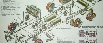
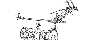
These vehicles are equipped with a brake drive with a fault signaling system, with separate axle braking (Fig. 1) and having a hydraulic vacuum booster and a vacuum cylinder with a shut-off valve in each circuit.
Rice. 1. Drive diagram of the brake system GAZ-3307, 66
I—vacuum; II—air; III—brake fluid; 1—engine inlet pipe; 2—shut-off valve; 3—vacuum cylinder of the front circuit; 4—signalling devices; 5—hydraulic vacuum amplifier of the front circuit; 6—vacuum cylinder of the rear circuit; 7—rear wheel brake mechanism; 8—rear axle housing; 9—pressure regulator; 10—hydrovacuum amplifier of the rear kennel; 11—air filter; 12—sensor for emergency brake fluid level drop; 13—filling tank; 14—main cylinder; 15—front wheel brake mechanism
Vacuum cylinders provide independent power to each circuit. The vacuum level is monitored by vacuum sensors with red indicators (on the instrument panel) for each circuit. The lighting of one of the indicator lamps indicates insufficient vacuum in the corresponding circuit.
A brake pressure regulator is installed in the hydraulic drive of the rear wheel brake mechanisms. Its functions in the event of failure of any of the two circuits are performed by the remaining serviceable circuit (front or rear axle).
At the same time, there is an increase in pedal travel by 90-115 mm. In this case, braking can occur with a gap between the pedal and the cabin floor of 15 mm.
Parts of the brake drive GAZ-3307, 66
The main brake cylinder GAZ-66, 3307 (Fig. 2) creates pressure in two independent hydraulic circuits of the brake drive with pistons 10 and 18. Primary cavity I ensures the operation of the rear brake circuit, and secondary cavity II ensures the operation of the front brakes.
The pistons of the main brake cylinder are equipped with floating heads 14, which act as a bypass valve.
In the initial (released) position, under the action of return springs 16, a gap is established between the head and the piston: the working cavities of the front and rear contours communicate with the tank 3.
Rice. 2. Brake master cylinder GAZ-3307, 66
I—primary cavity; II—secondary cavity; 1—protective cap; 2—sensor for emergency brake fluid level drop; 3—additional tank; 4—connecting sleeve; 5—tube; 6—tank fitting; 7 and 20—hulls; 8—protective cap; 9—pusher; 10 and 18—pistons; 11—thrust bolt; 12—head sealing ring; 13—cuff; 14—piston head; 15—thrust rod; 16—return spring; 17—primary piston stop; 19—piston head spring; 21—secondary piston stop; 22—valve plate; 23—overpressure valve; 24—fitting
When you press the brake pedal, the pistons move, the heads 14, under the action of the springs 19, are pressed against the end of the pistons, separating the working cavities from the reservoir, and pressure is created in the drive.
The seal is ensured by rubber rings 12 installed in the piston heads. Valves 23 maintain an excess brake fluid pressure of 40–80 kPa (0.4–0.8 kgf/cm2) in the system.
Failure of one of the circuits of the GAZ-66, 3307 brake system is accompanied by an increase in the brake pedal travel due to idle movement of the piston of the faulty circuit. A healthy circuit creates the brake fluid pressure necessary for braking.
To replace worn parts, it is necessary to remove the unit from the car, disconnect housings 7 and 20, unscrew the thrust bolts 11 and remove the pistons.
Before assembly, wash all parts with clean brake fluid. Do not allow foreign particles, dirt, or oil to enter the unit.
Check for a gap of 0.4-1 mm between the end of the piston and the sealing ring 12 by pressing the head 14 with your hands until it stops. When assembling the unit, the thrust bolts 11 must fit into the grooves of the pistons.
The GAZ-3307, 66 brake system is powered from tank 3. With sensor 2 removed and new brake linings, the fluid level in the tank should be at the level of the “MAX” mark.
A decrease in the fluid level during operation with a working brake system is associated with wear of the linings in the brake mechanisms, so you should not pour fluid into the reservoir, since after installing new linings the fluid level rises to normal.
When the brake fluid level warning light comes on, it indicates a leak in the brake system. In this case, it is necessary to add liquid only after the system’s tightness has been restored.
To check the serviceability of the emergency liquid level drop sensor, with the ignition on, press on top of the central part of the protective cap 1. In this case, the warning light on the instrument panel should light up.
Hydraulic vacuum brake booster GAZ-3307, 66
The hydraulic vacuum brake booster GAZ-3307, 66 (Fig. 3) is installed in each circuit of the brake system and makes it possible to stop the car with less physical force from the driver.
The operating principle of a hydraulic vacuum brake booster is to use vacuum in the engine intake pipe to create additional pressure in the hydraulic drive system of the service brake system.
If the vacuum pipeline or hydraulic vacuum booster fails or leaks, braking efficiency is sharply reduced.
As a result of a leak in the vacuum system, a constant leak of air occurs into the engine intake pipe, which depletes the mixture in the seventh and partially in the fourth cylinder so much that ignition from a spark does not occur.
The unburned working mixture washes away the lubricant from the cylinder bore and leads to dry friction of the piston and piston rings on the liner, and the presence of road dust aggravates dry friction and leads to emergency wear of parts in these cylinders.
Rice. 3. Hydraulic vacuum brake booster GAZ-3307, 66
1—diaphragm; 2—body; 3—diaphragm plate; 4—piston pusher; 5—spring; 6—vacuum valve; 7—atmospheric valve; 8—body cover; 9—atmospheric valve spring; 10—control valve body; 11—valve spring; 12—control valve piston; 13—bypass valve; 14—piston; 15—piston valve; 16—piston cuff; 17—valve pusher; 18—piston thrust washer; 19—cylinder
The hydraulic brake booster consists of a booster chamber, a hydraulic cylinder and a control valve. The chamber body is connected to the inlet pipe and the atmosphere through a control valve.
The shut-off valve of the GAZ-66, 3307 brake system is installed in the vacuum cylinder of each circuit. When the engine stops, it automatically disconnects the intake pipe from the vacuum bottle. This makes it possible, due to the vacuum reserve in the system, to perform four to five effective brakes.
The brake pressure regulator adjusts the brake fluid pressure in the rear brake drive depending on changes in the load on the rear wheels to prevent the vehicle from skidding during heavy braking.
Repair manual
Due to the fact that GAZ-3307 and GAZ-3309 trucks are domestic vehicles, their repair usually does not become an impossible task. Spare parts are available in any dismantling or automotive market.
Buying them is not a problem, and thanks to the availability of an accessible and understandable instruction manual, not only the service station technician, but also the owner of the car can replace relatively simple spare parts.
Getting a car owner's manual is not a problem. It can be downloaded from specialized websites on the Internet or bought a printed version in a store or market.
Name: GAZ-3307, 3309. Operation, maintenance and repair manual. Publisher: Third Rome Year: 2007 ISBN: 5-88924-367-3 Number of pages: 186 Format: PDF Size: 93.33 MB Language: Russian
Of course, if we talk about more serious breakdowns, then the owner will not be able to do the kind of diagnostics that can be carried out by technicians at a service station on his own. In addition, there are a sufficient number of users on the Internet who have been “communicating” with GAZ 3307 and GAZ 3309 for a long time, and will be able to share their experience. You can meet such people on forums dedicated to the repair and maintenance of this car.
Engine repair process
Types of GTZ
The main brake cylinder can be one- or two-section . But the first type is practically no longer used today - these were, for example, on GAZ-53 trucks.
Single-section GTZ from a GAZ 53 car
Two-piece master cylinder for Honda Accord
Also, the main brake cylinders may differ in the presence or absence of a brake booster. But again, all modern cars are equipped with vacuum brake boosters.
Therefore, the vast majority of cars that are in use today are equipped with two-section GTZs with vacuum brake boosters.
Brake system repair
Malfunctions of the brake system must be eliminated immediately or as soon as possible - brakes are directly related to traffic safety. Malfunctions include:
- Increased free play of the brake pedal, in some cases the brakes do not grab the first time, and the part requires two pedal strokes or more;
- Pedal hardness. The pedal becomes tight, and braking efficiency decreases;
- The brake fluid level light in the car lights up, indicating a lack of fluid in the brake system;
- The brake pedal grabs at the very beginning or there is no free play at all.
______________________________________________________________________________
Brake system of Gazelle GAZ-2705 cars
Working brake system of the Gazelle GAZ-2705 The Gazelle GAZ-2705 uses a hydraulic brake drive, which consists of a two-chamber vacuum booster 3 (Fig. 21), a two-piston master brake cylinder 2 with a reservoir, a pressure regulator 5 installed in the rear brake drive.
Fig.21. Drive diagram of the service brake system Gazelle GAZ-2705 I - front brake circuit; II - rear brake circuit; 1 — front brake mechanism; 2 — main brake cylinder; 3 - vacuum booster; 4 — rear brake mechanism; 5 - pressure regulator; 6 — rear axle axle housing; 7 - indicator The front drive circuit acts on the disc brakes of 1 front wheels, the rear circuit - on the drum brakes of 4 rear wheels. In the reservoir of the main brake cylinder of the Gazelle GAZ-2705, a float indicator 7 is installed for an emergency drop in the brake fluid level. Vacuum brake booster Gazelle GAZ-2705 To reduce the force applied to the brake pedal, a two-chamber vacuum booster (Fig. 22) is installed between it and the main brake cylinder (Fig. 22), activated by vacuum in the engine intake pipe.
Fig.22. Vacuum brake booster Gazelle GAZ-2705 A1, A2, A3, A4 and A5 - cavities of the vacuum booster; A6 - holes; 1 - check valve; 2 - sealing sleeve; 3 and 16 — pushers; 4 — adjusting bolt; 5, 10, 17 — pistons; 6 - cover; 7 and 8 - diaphragms; 9 — thrust ring; 11 — amplifier housing; 12 — guide rings; 13 — sealing cuffs; 14 - filter; 15 — valve body; 18 — valve diaphragm; 19 - screw; 20 — jet washer; 21 - spring; 22 - piston connector The Gazelle GAZ-2705 brake booster consists of a housing 11, a housing cover 6, a thrust cover, into which pistons 5 and 10 with diaphragms 7 and 8 are installed. A secondary piston 5 is attached to the threaded end of the piston connector 22 using a nut, and A piston 10 and a diaphragm 18 are attached to the flange part of the connector using six bolts, which are screwed into the valve body 15. In the body of 15 valves of the GAZ-2705 vacuum brake booster, two screws 19 secure the pusher 16 with piston 17 and filter 14. In piston 10 is installed a reaction washer 20, through which the total force from the pusher 16, directly connected to the brake pedal, and from both pistons of the amplifier is transmitted to the pusher 3. To ensure the release of the system, a gap is required between the pusher 3 and the primary piston of the main brake cylinder. The gap is ensured using adjusting bolt 4.
The bolt head should be recessed 1.35-1.65 mm relative to the mating plane of the cover to which the master cylinder flange is attached. Main brake cylinder GAZelle GAZ-2705 The main brake cylinder with two successively arranged pistons 10 and 17 (Fig. 23) and a two-section reservoir 4 with sensor 6 for an emergency brake fluid level drop indicator is attached to the cover of the vacuum booster. The main brake cylinder of the Gazelle GAZ-2705 creates pressure in two independent hydraulic circuits. The volume of brake fluid between pistons 10 and 17 is used to operate the rear brake mechanisms, and the volume of fluid between piston 17 and the end of the plug 20 is used to operate the front brake mechanisms.
Fig.23. Main brake cylinder Gazelle GAZ-2705 1 - housing; 2 - tube; 3 — connecting sleeve; 4 - tank; 5 — protective cap; 6 — sensor for emergency brake fluid level drop; 7 - thrust ring; 8 — outer cuff; 9 — guide sleeve; 10, 17 — pistons; 11 — retaining ring; 12 - sealing ring; 13 — piston washer; 14, 16 — cuffs; 15, 18—thrust washers; 19 — spring: 20 — plug; A, B - compensation holes; C - bypass holes When braking, moving forward, the primary piston 10 and its cuff 15 block the compensation hole B, connecting the primary cavity of the main brake cylinder of the Gazelle GAZ-2705 with the reservoir. The spring installed between the pistons 10 and 17 is stronger than the spring 19 located between the piston 17 and the plug 20, therefore, simultaneously with the primary piston 10, the secondary piston 17 begins to move, covering with a cuff the compensation hole A, connecting the secondary cavity of the cylinder with the tank. Further movement of the pistons is accompanied by an increase in pressure in the cavities, and, consequently, both brake circuits are activated. When the force is removed from the brake pedal, the pistons of the main brake cylinder of the GAZelle GAZ-2705 return to their original position under the action of springs. In this case, compensation holes A and B open and the liquid in both cavities of the main cylinder communicates with the liquid in the tank, while the pressure in the circuits decreases to atmospheric pressure. If the brake pedal is released abruptly, then the pistons of the master cylinder of the Gazelle GAZ-2705 brake quickly return to their original position and are ready for subsequent braking. The rapid return of the pistons is ensured by the fact that when they return to their original position, a vacuum is created in the cavities of the main brake cylinder, under the influence of which the liquid from the tank through the bypass holes C and the holes in the pistons, pressing the washers 13 and the edges of the cuffs 14, enters the cavities of the main cylinder. When the pistons reach their original position, excess fluid from each cavity will flow through compensation holes A and B into the reservoir. If one of the drive circuits fails, fluid leaks from the cavity of the main brake cylinder of the Gazelle GAZ-2705, connected to the faulty circuit. If the rear circuit is faulty, then the piston 10 reaches the spring holder 16 and through it acts on the secondary piston 17, which creates pressure in the secondary cavity of the master cylinder and the front circuit. If the circuit of the front brake mechanisms of the GAZelle GAZ-2705 fails, piston 17 acts on the end of the plug 20, and piston 10, compressing the spring, displaces fluid from the primary cavity of the master cylinder into the circuit going to the brake mechanisms of the rear wheels. If one of the drive circuits fails, the brake pedal travel increases, but sufficiently effective braking of the vehicle is ensured. If the circuits are working properly, the brake fluid level in the reservoir of the main cylinder of the GAZelle GAZ-2705 should be between the MAX and MIN marks.
A gradual change in the fluid level from MAX to MIN is associated with wear of the brake linings. A sharp drop in the level of brake fluid in the reservoir indicates a violation of the tightness of the brake system. At the same time, the brake fluid level alarm is activated and a red lamp lights up on the instrument cluster. In this case, liquid should be added only after the system’s tightness has been restored. To check the serviceability of sensor 6 for an emergency drop in the liquid level in the tank, with the ignition on, press on top of the central part of the protective cap 5. In this case, the lamp on the instrument cluster should light up. Brake pressure regulator Gazelle GAZ-2705 Pressure regulator Gazelle GAZ-2705 (Fig. 24) adjusts the pressure of the brake fluid supplied to the brake mechanisms of the rear wheels, depending on the load of the car, which prevents the car from skidding during heavy braking.
Fig.24. Brake pressure regulator Gazelle GAZ-2705 C = 28-32 mm (for buses), 13-17 mm (for vans); 1—press lever; 2 - pin; 3 — fixing bolt; 4 — axis of the pressure lever; 5 - nut; 6 - axis; 7 — body; 8 and 9 — regulator brackets; 10 - lock nut; 11 — adjusting bolt; 12 — load spring; 13 - spring; 14 — piston sleeve; 15 — control cone; 16 — pressure spring; 17 - ball; 18 — thrust bracket; 19 — return spring; 20 - bushing; 21 - piston; 22 — protective cover; 23 — bridge bracket; 24 - stand; 25 - spring washer The Gazelle GAZ-2705 brake pressure regulator is attached to the left frame side member through bracket 8, and is connected to the rear axle using load spring 12 and strut 24. The load spring with its upper short end acts through the pressure lever 1 on the outer end of the piston 21, and with its long end through the rack 24 it is connected to the bracket 23 welded to the rear axle of the car. The GAZelle GAZ-2705 brake pressure regulator consists of a housing 7, into which a sleeve 14 is installed and a sleeve 20 is screwed in. The stepped piston 21 is mixed in the sleeve and sleeve, while in cavity I, permanently connected to the main cylinder, there is a part of the piston of small diameter, and in cavity II, permanently connected to the wheel cylinders of the rear brake mechanisms, it has a larger diameter. A control cone 15 is attached to the piston, which acts on a ball 17 located in the hole of the sleeve 14. The ball is held in the hole by a leaf spring 16. The load spring 12, the force of which is directly proportional to the vehicle load, determines the start of the regulator activation, and the difference in piston diameters determines the pressure adjustment fluid flowing to the rear brake mechanisms. Before the Gazelle GAZ-2705 brake pressure regulator comes into effect, the fluid pressure in cavities I and II is the same, since under the action of spring 19 and load spring 12, piston 21 is pressed through thrust bracket 18 to sleeve 14, and ball 17 is lifted from the seat by the control cone 15, which ensures the free passage of liquid from cavity I to cavity II. When braking, at first the fluid pressure in cavities I and II will be the same until the force received from the pressure on most of the piston 21 (cavity II) is greater than the sum of the forces obtained from the action of springs 12 and 19 and from the fluid pressure on the area formed between the large and small diameters of the piston (cavity I). In this case, the piston will move to the left (according to the figure), the control cone 15 will move away from the ball 17, which will move into the seat of the sleeve 14, thereby disconnecting cavity I from cavity II.
From this moment, the fluid pressure in cavity II, supplied to the rear brake mechanisms of the Gazelle GAZ-2705, will increase more slowly and will be less than in cavity I. When the force is removed from the brake pedal, the pressure in cavity I drops, piston 21 will return to its original position (to the right in the figure), and the control cone, lifting the ball, will open the access of liquid from cavity II to cavity I. The piston sleeve 14, under the influence of pressure in cavity II, will move to the left (according to the figure), and the ball 17 will move away from the seat under the action of the control cone 15, opening the access of liquid from cavity II to cavity I. After the liquid pressure drops, the piston sleeve 14 and piston 21, under the action of the return spring washer 25 and spring 19, will return to their original position. Wheel brake mechanisms of the Gazelle GAZ-2705 The brake mechanisms of the front wheels of the Gazelle GAZ-2705 are disc brakes with a floating caliper. Brake disc 1 (Fig. 25) has ventilation holes to reduce heating during braking and is mounted on the wheel hub of the front axle.
Fig.25. Brake mechanism Gazelle GAZ-2705 front wheels 1 - brake disc; 2 — brake caliper base; 3 — brake caliper body; 4 — brake pads; 5 - piston; 6 - sealing ring; 7 and 9 — protective covers; 8 and 12 - bolts; 10 — guide pin; 11 — wheel hub; 13 — pad spring; 14 — brake fluid supply hose; 15 — guide pin; 16 - bleeding valve The floating bracket of the Gazelle GAZ-2705 brake mechanism consists of a base 2, which is attached to the steering knuckle, and a body 3, which is movably connected to the base through guide pins 15. Protective covers protect your fingers from dirt and moisture. Housing 3 contains a piston 5 and its sealing parts: ring 6 and a protective cover 7. To remove air from the housing cylinder, a bleeding valve 16 with a cap is provided. The Gazelle GAZ-2705 brake pads are located in a groove in the base and are pressed against the ledges of the base by springs attached to the pads. To protect the working surfaces of the disc and pads from dust, dirt, and grease, a special shield is installed. When braking from the fluid pressure in the hydraulic drive, the piston 5, moving in the housing 3, presses the inner brake pad to the disc 7, and the housing itself, moving on the pins 15 in the direction opposite to the movement of the piston, presses the outer pad to the disc. The pressing force of both pads to the disc is the same and is directly proportional to the pressure in the hydraulic drive. When the brakes are released, the pads move away from the brake disc of the Gazelle GAZ-2705 by a constant amount determined by the rigidity of the piston O-ring 6. This achieves automatic adjustment of the gap between the pads and the disc and compensates for the wear of the linings. The brake mechanisms of the Gazelle GAZ-2705 rear wheels are shoe, drum type (Fig. 26). The brake mechanism consists of a brake shield 4, on which the working cylinder 2, a pad support with a plate 13, and pads 5 are mounted.
Fig.26. Brake mechanism of the rear wheels of Gazelle GAZ-2705 1 - wheel cylinder mounting bolt; 2 — wheel cylinder; 3 — bleeding valve; 4 — brake shield; 5 — block; 6 — protective cover; 7 - piston; 8 - thrust ring; 9, 10, 14 and 28 - springs; 11 — expansion link; 12 — driving lever of the parking brake; 13 — pad fastening plate; 15 — cotter pin; 16 - nut; 17 and 18 — washers; 19 - bolt; 20 and 22 - plugs; 21 and 23 — eccentric bushings; 24 - eccentric; 25 — eccentric axis; 26 - nut; 27 - cups; 29 — rod; 30 - cable of the parking brake system Brake pads Gazelle GAZ-2705 with their upper ends enter the slots of the piston rods, and their lower ends touch the support plate, on which they are held using tension springs 9 and 14. Lateral fixation of each pad on the shield is provided at three attachment points, to with which spring 28 presses it. The wheel working cylinders of the Gazelle GAZ-2705 have a special device that maintains a constant gap between the brake drum and the pads as the linings wear out. This device consists of a persistent split metal ring 8, installed with interference fit into the brake cylinder. The ring cut is located in the upper part of the cylinder near the bleeder hole. The piston 7 is inserted into the central hole of the thrust ring so that after turning it 90°, the slot on the piston rod is parallel to the plane of attachment of the cylinder to the shield. The piston rests against the ring and can move freely in it towards the pads within 1.7-1.9 mm. As the brake linings and the Gazelle GAZ-2705 drum wear out, the piston, when braking under fluid pressure, moves in the cylinder, dragging the thrust ring 8 with it. After braking, the piston, under the action of the tension springs of the pads, will move relative to the ring by the above amount, which will ensure a constant gap between the pads and a drum. Brake drums Gazelle GAZ-2705 are solid cast, made of gray cast iron. The rear brake mechanism includes parts of the parking brake system: drive lever 12, expansion link 11 and mechanical adjustment parts 21, 23, 24, 25. Parking brake system of the GAZelle GAZ-2705 parking brake system of the GAZelle GAZ-2705 (Fig. 27) has mechanical drive acting on the brake mechanisms of the rear wheels. The drive consists of a lever 1, a front cable 2 and rear cables 5 and 8, connected to each other by an equalizer 9 and secured to a bracket 4 welded to the frame cross member.
The rear cables act on the levers 7 and expansion links 6 located in the brake mechanisms of the rear wheels.
Fig.27. Parking brake system Gazelle GAZ-2705 1 — lever; 2 — front cable; 3 - nut; 4 — bracket; 5 and 8 — rear cables; 6 — expansion link; 7 — drive lever; 9 - equalizer When lever 1 is acted upon through a system of cables 2, 5, 8 and levers 7, the brake pads of the GAZelle GAZ-2705 are pressed against the drums, producing braking. Lever 1 is fixed using a ratcheting mechanism consisting of a pawl and a gear sector. In this case, the switch located on the lever mounting bracket in the cab turns on a red lamp on the instrument cluster. When releasing the brake, the lever should be returned to its original position. To do this, you need to recess the button at the end of the lever handle. The rod connecting the button to the pawl will disengage the pawl from engagement with the sector. Under the influence of hand force, brake springs and rear cables, the parking brake system is released. The warning light on the instrument cluster goes out. The parking brake of the Gazelle GAZ-2705 does not require repairs, except for its adjustment. The condition of the cable drive should be checked. If the protective shells or cables are damaged, the cable assembly must be replaced. If the parking brake locking parts wear out, they also need to be replaced. Adjusting the parking brake drive of the Gazelle GAZ-2705 If, when braking the Gazelle GAZ-2705 car with the parking brake, lever 1 (see Fig. 27) when a force of 600 N (60 kgf) or more is applied to it is fixed on the outermost upper teeth of the sector, then you should adjust adjust the drive in the following order: — set the drive lever to the lowest position; — remove plugs 20 (see Fig. 26) in the brake mechanisms of the rear wheels. Using a 17 mm star wrench, loosen the nut securing the eccentric of the adjusting mechanism of one of the brakes by 1.0-1.5 turns; - eliminate the gap between the expanding link 11 and the lever 12, for which, using a special tubular wrench measuring 9 mm, turn the eccentric bolt 25 in the direction indicated by the arrow until rotational resistance is felt, which is associated with the expansion of the pads (the movement of the pads can begin also determined through inspection windows in the panel); — tighten the eccentric fastening nut to a torque of 24–35 Nm (2.4–3.5 kg/cm) in the position where the pads begin to decompress. In this case, using a 9 mm wrench, you should hold the eccentric bolt 25 from turning; — adjust in a similar way the position of the expansion link 11 in the other brake mechanism; — install plugs in the brake mechanisms of the Gazelle GAZ-2705; — check the presence of gaps between the tips of the cables 5 (see Fig. 27) and 8 and the depressions on the equalizer 9. The gaps are eliminated by tightening the nuts securing the cables on the bracket 4. The adjustment should be made in such a way that after adjustment the equalizer is at a distance B from the front wall bracket and perpendicular to the longitudinal axis of the vehicle. With a correctly adjusted parking brake drive of the Gazelle GAZ-2705, the drive lever under a force of 600 N (60 kgf) should not move more than 15 teeth of the locking mechanism.
______________________________________________________________________________
______________________________________________________________________________
- Clutch GAZ-3308, 3309
- Dismantling the GAZ-3308, 3309 gearbox
- Drive axles GAZ-3308
- Transfer case and cardans GAZ-3308
- Cardans GAZ-3307, 3309
- Rear axle GAZ-3309, 3307
- Suspension GAZ-3309
- Steering GAZ-3309
______________________________________________________________________________
______________________________________________________________________________
- Clutch GAZ-53, 3307
- Gearbox GAZ-53, 66
- Rear axle GAZ-53
- Steering GAZ-53, 66
- Ignition installation GAZ-53
- Clutch GAZ-66
- Drive axles GAZ-66
- Brake system GAZ-66
- Winch and power take-off GAZ-66
- Operating systems of the GAZ-66, GAZ-3307 engine
- Engine ZMZ-402 Gazelle GAZ-2705
- Clutch Gazelle GAZ-2705
- Gazelle GAZ-2705 gearbox
- Front axle Gazelle GAZ-2705
- Cylinder head and camshaft Cummins ISF 2.8
- Fuel system of the Gazelle Cummins ISF 2.8 engine
- Cylinder block and piston group of the Cummins ISF 2.8 engine
- Crankshaft engine Cummins ISF 2.8 Gazelle
- Engine Cummins Valdai GAZ-33106
- Clutch and gearbox Valdai
- Bridges Valdai
- Steering Valdai
Catalogs of spare parts and assembly parts
Clutch repair
3307 trucks often operate at maximum loads. A fully loaded car cannot drive in one gear when going uphill, and shifting gears in this mode forces the clutch to work quite hard. In addition, the 3307 gearbox is not synchronized and requires double squeezing when changing from one gear to another. Due to the heavy load on the clutch, it often fails and has to be repaired.
Signs of poor clutch are determined by pedal pressure:
- It fails, the gears cannot be engaged;
- Doesn’t squeeze out completely and sticks up;
- The pedal is too “soft”;
- Large free movement, squeezing occurs at the very end.
There are cases when the pedal pressure is normal, but when the gear is engaged, the car does not move.
Clutch diagram for GAZ 3307
The cause of the malfunction can be almost all clutch parts. Often fail:
- “Basket” and clutch disc;
- Release bearing;
- Master and slave cylinder;
- Clutch fork.
A little more detail about each detail:
- Driven clutch disc. The wear of the disc linings can be determined without removing it from the car. You need to remove the clutch housing tray - and then the disc linings can be seen. Linings that are too thin indicate the need to replace the part. Sometimes the disc hub breaks, and then the car does not move when the gear is engaged. Such a malfunction can also be determined on the spot. Two people need to do the check. One squeezes the clutch with the engine not running, the other moves the disc with a screwdriver. The break will be noticeable by the uneven movement of the disk.
- Clutch drive disc (“basket”). The “basket” of a gasoline engine is claw-type (three legs), the height of the legs is adjusted using nuts. Accuracy is very important here - incorrect adjustment affects the movement of the car: when starting off and when changing gears. The car can:
- twitch at the beginning of movement;
- gears on an unadjusted clutch engage with a crunch;
- the clutch can “drive”, but the car will not move.
- Release bearing with bore. The unit consists of two parts - the hub and the bearing itself. The hub has an oiler - the rubbing surface on which the hub moves is lubricated. The bearing itself must have a lithol type lubricant inside. A dry bearing can jam, and in this case the varnishes of the clutch “basket” will instantly wear out.
- Clutch master and slave cylinders. If the master cylinder fails, the pedal becomes soft (“wobbly”) and the clutch periodically disappears. A faulty slave cylinder usually leaks. You can try changing the cuffs inside the cylinders, but if the parts are old enough, it is better to replace them.
- Release bearing fork (clutch fork). The part is very simple, but its malfunction can most often be seen only when the fork is removed. Three characteristic defects of the part:
- the tips in connection with the release bearing hub are worn out;
- the fork bursts in the area of the swivel joint (“soldier”) or in the place where the rod is attached;
- the fork bends.
Selection and purchase of GTZ
It is best to select a GTZ based on the car’s VIN code, although you can get by with the make, model and type of engine. The part does not have different options to choose from, so the only option to choose from is the manufacturer. Choose reliable brands, because the operation of the GTZ is critical to your safety. The website partreview.ru has good reviews for products from the brands TRW, ATE and LPR.
As mentioned above, sometimes you can get by by replacing parts of the GTZ repair kit. But if the housing itself or components not from the repair kit are worn out or damaged, the entire master brake cylinder is replaced.
Related terms
- ABS (Anti-lock braking system)
- Vacuum brake booster
The device of the main brake cylinder gas 31105
Post by Serzhi » Sun Nov 02, 2014 12:47 pm
Background: It’s time to install brakes on your project; I have a hydraulic brake booster (assembled with the main one) from a BMW 7 on the farm. it will be delivered after the installation of the V-shape + power steering, so I’m making a temporary solution, especially in the warehouse there are 3 GTZ from the Volga 3110, the good stuff won’t go to waste!
On the left is the original GAZ from donor 3102, used on BSK, in the center is the original GAZ from Iriska, worked on DOT3 and on the right - Phenox from the Black donor, worked on BSK. Phoenix was without its original cover (
What I love about my original spare parts is the inscriptions in Russian. I'm just dragging myself!
But it is transparent, which is a plus - the brake level is clearly visible. And also one of the reasons for the poor performance of the main brake on almost any Volga is a huge amount of any mister in the brake fluid! Which precipitates like the bottom of a tank
This is how it collects inside, but more on that a little later. Remember - the brake fluid should be transparent, and there should be no sediment in the reservoir, especially such a dense one
I clean up a little and decide what to put on my project (code name Iriska)
“Choose me!”, each of them shouts))))
But it’s cloudy (. Well, the original, you turn yellow so much. Like ivory bone, after 10 unfortunate years... ( But the inscription is in Russian! But on the side the plastic has already wrinkled with a network of age-related cracks and wrinkles... Take it from 3102? And there are wrinkles there too , more dense than Toffee, and the lid is yellower
Well, if that’s the case, I’ll take the white-faced Phoenix.
Washing the Butterscotch cap
Bah, the rubber cap on the cork doesn't fit anymore(
I don’t understand how you can even drive with such a cap...))))
It’s good that the tank from 3102 is like new
I try to screw the lid on and... doesn’t fit( Maybe the float is resting? Yes, it doesn’t seem like it should... Ah, that’s the reason((((The unification failed, and I don’t have a cover from the Phenox. The threads are different.
So I take the butterscotch bottle! Yes, a little yellow, but a little old
But the inscription, you can forgive everything for it!
I’ll put it on for now and slowly look for the original tank with a Russian inscription, but transparent. Maybe I'll get lucky?
And what about the main cylinders themselves: the first main one. Original GAZ, year of manufacture unknown, but clearly earlier than 2000
Volgovodians, do you still go to BSK? Then don’t complain about bad brakes - inside the main thing there is such a “chacha” - traces of work on the brake brake brake system. a cross between shoe polish and plasticine.
Believe me, this is not the first time I have seen this when working at BSK.
Sadly. but fixable - there are no obvious sinkholes. but traces of work on the cuffs are visible. Theoretically, it can be polished, so I put it off
Now I take the main brake Phoenix.
I disassemble (Phenox from below, GAZ from above)
Here it is - unification and marketing of oneself.
There were 2 cuffs, now there is one, and even an ordinary round ring instead of a cuff
There were stainless steel rods, black steel ones, in the photo they were so rusty from insertion in literally 10-15 minutes
There was a thrust washer at the end under the cuff, but now it is gone. As well as a metal rod centering ring. instead there are fluoroplastic washers. and two.
What about the mirror? Bah, this is some kind of distorting mirror. ulcers, shells, palpable with a fingernail.
Put it in the ferrous metal box (I use separate waste accumulation)!
Next up is the main original GAZ with its Toffee, 2000
This is what it's like to drive on a DOT brake! purity!
Brake device
The brake system of the GAZ 53 is also a representative of the previous generations of the automotive industry and cannot boast of a minimum braking distance or extremely effective braking. As a rule, it is generally impossible to stop this car abruptly, but, equivalent to this fact, it does not accelerate to too high speeds. But those who still operate this car still have to somehow monitor its technical condition of the braking system. This is what we will talk about today.
A vehicle's braking system is designed to generate braking force that will counteract the rotational force of the wheel at the very point where the wheel makes contact with the road. Of course, if the wheel instantly froze, this would lead to the rubber rubbing against the asphalt, so the wheel continues to rotate, slowing down until the car comes to a complete stop, if required. The braking distance of a car depends on the design of the entire braking system; of course, for a GAZ 53 with a full load and at high speed it will be very long. As a rule, the drivers of this truck simply do not accelerate to very high speeds in order to be able to stop if something happens.
So, the experimental truck has two subsystems at its disposal:
- Working.
- Parking lot.
The parking brake system has a curious design. Typically, as is done today, the parking system is provided by standard brake mechanisms that simply clamp the rear wheels. Here, engineers designed a more interesting device. When the driver changes the position of the parking brake lever and activates it, a special mechanism presses the pads on the car's propeller shaft immediately after the gearbox. This results in the rear wheels being unable to rotate as the driveshaft must rotate to do so. However, in an emergency situation, if the working system fails, stopping the car with the parking brake will be difficult due to just this design. The working system has a standard appearance for that time and is of the usual hydraulic type. It is activated by pressing the brake pedal and is used by the driver constantly while driving the car. By the way, often on a large slope, even experienced GAZ 53 drivers start off using the handbrake in order to get under way without rolling back. And this design of the parking brake greatly simplifies this operation for them.
Auto catalog
Interchangeable with a part released earlier under the same number VK-21-3500105-A Set of parts for the brake master cylinder (for spare parts) Additional information: Quantity for “52-01, 52-03” 1 Model Р'Рљ- 21 Group Brakes Subgroup 3500 Serial part number 105 Additionally Interchangeable with a part previously released under the same number OKPO class 45 Products of the automotive industry OKPO subclass 4 Units, components and parts of passenger cars, motorcycles, bicycles and electric vehicles Product type 30-39 - bolts Type coating 1 - zinc with chromating (zinc plating and passivation (P29) 1 51-3505060 Brake master cylinder piston pusher assembly Additional information: Quantity for "52-01, 52-03" 1 Model 51 Brake group Subgroup Main brake cylinder ( hydraulic brakes) Part number 060 2 51-3505065
Operating principle of the vacuum brake booster gas 3307
GA3-3307.
A hydraulic vacuum brake booster (Fig. 42) is installed in each circuit of the brake system and makes it possible to stop the car with less physical force from the driver.
The principle of operation of the booster is to use vacuum in the engine intake pipe to create additional pressure in the hydraulic drive system of the service brake system.
If the vacuum pipeline or hydraulic vacuum booster fails or leaks, braking efficiency is sharply reduced.
As a result of a violation of the tightness of the vacuum system, a constant leak of air occurs into the engine intake pipe, which depletes the mixture in the seventh and partially in the fourth cylinder so much that it does not ignite from a spark. The unburned working mixture washes away the lubricant from the cylinder bore and leads to dry friction of the piston and piston rings on the liner, and the presence of road dust aggravates dry friction and leads to emergency wear of parts in these cylinders.
The hydraulic vacuum booster consists of a booster chamber, a hydraulic cylinder and a control valve. The chamber body is connected to the inlet pipe and the atmosphere through a control valve.
The operation of the hydraulic vacuum amplifier can be understood using the diagram shown in Fig. 43. If the engine is running and the brake pedal is not pressed, then the vacuum formed in the intake pipe
is transmitted to cavities I and II of the control valve and to cavities III and IV of the amplifier chamber housing. In this case, the pressure on the diaphragm 1 of the amplifier on both sides is the same, and under the action of the spring 5 it takes its original position.
When you press the brake pedal, fluid from the master cylinder is supplied under pressure through a pipeline to the hydraulic cylinder of the booster. The fluid then passes through the hole in the piston 14 and is directed to the working brake cylinders of the vehicle wheels. At the same time, pressure is created on the piston 12 of the amplifier control valve.
Initially, the brake fluid pressure is the same throughout the entire hydraulic line. With a further increase in pressure, the piston of the control valve will overcome the resistance of the spring and close the vacuum valve 6. At this time, cavities I and II are separated. With further movement of the piston, atmospheric valve 7 opens. Atmospheric air enters cavity III of the hydraulic vacuum amplifier through the air filter.
The pressure difference in cavities III and IV is transmitted through the diaphragm and pusher to the piston 14 of the amplifier cylinder, which creates additional pressure in the hydraulic line.
When the pressure is removed from the brake pedal, the pressure in the hydraulic line between the master cylinder and the control valve drops. This allows the control valve spring to return the control valve piston to its original position due to its compression force. In this case, the atmospheric valve 7 closes and the vacuum valve 6 opens. The same vacuum is established in cavities I, I, III, IV.
Diaphragm 1, under the action of spring 5, moves to the left and, together with the rod, returns to its original position. Piston 14 will reach the thrust washer, and valve 15 will open.
The fluid displaced into the line during braking is returned back to the master cylinder, and the brake system is completely released.
Rice. 42. Hydraulic vacuum booster: 1—diaphragm; 2—body; 3—diaphragm plate; 4—piston pusher; 5—spring; 6—vacuum valve; 7—atmospheric valve; 8—body cover; 9—atmospheric valve spring; 10—control valve body; 11—valve spring; 12—control valve piston; 13—bypass valve; 14—piston; 15—piston valve; 16—piston cuff; 17—valve pusher; 13— piston thrust washer; 19—cylinder
Rice. 43. Diagram of the operation of a hydraulic vacuum amplifier. Braking torque: I, II, III and IV—cavities (For the names of positions on the diagram, see Fig. 42)
Main brake cylinder Volga 31105 2004-2009
Repairing auto parts yourself is a responsible task that should be taken as seriously as possible. Sometimes a faulty spare part takes the driver by surprise, forcing him to spend a lot of time and money searching for a good service station, but there is an alternative solution to the problem; this requires a small amount of knowledge and a set of tools.
When the main brake cylinder of a Volga 31105 2004-2009 is being repaired, you need to be extremely careful and not neglect the little things. To get acquainted with the issue, car enthusiasts often use various Internet portals dedicated to auto parts. Some of them use narrowly focused forums. But, as a rule, only generalized information is provided there, which is known initially. Where can you find a reliable source that offers really useful things? Our portal is open for this 24 hours a day. Online mode allows us to help clients at any time convenient for them. Moreover, a mobile version has been developed that is available to everyone.
A detailed description of such a unit as the main brake cylinder Volga 31105 2004-2009 has a good structure with thematic headings. In addition, there is always the opportunity to familiarize yourself with the intricacies of installation. There are often situations when a driver is confident in his abilities, but when he gets down to work, questions begin to arise. Thanks to our portal, such moments can be easily avoided. The site is a database that is updated regularly. By using it as a support during repair work, the car enthusiast receives a serious advantage. Each of the articles has reliable support, tested in practice.
Diagnostics
First, we pay attention to the parameters of the control devices on the dashboard inside the car. If there is a problem with the braking system, the indicator will light up. Then we inspect the master cylinder body to see where the brake fluid is leaking. We pay special attention to the junctions of the pipeline and circuit outlets. During the inspection of the case, we identify mechanical damage (if any). Then we measure the pressure in the circuits. To do this, we attach a pressure gauge to the holes on these devices.
We compare the measurement results with the control parameters specified by the manufacturer in the vehicle repair and operating instructions. A difference in measurements will indicate a circuit failure. We can only check the tightness of the master brake cylinder on a special stand.
avtoexperts.ru
So, if the car is rear-wheel drive, that is, there is a division, the first circuit is responsible for the front pairs of wheels, the second for the rear ones. However, if we are talking about a front-wheel drive vehicle, then the distribution of responsibility occurs diagonally: L.P./P. Z. and P.P./L.Z. The main brake cylinder has two main types: • With a bypass hole directly in the cylinder body. • With bypass valve in the piston.
GTZ, where bypass valves are installed on the piston, are used for installation on cars with ABS systems.
The fact is that in addition to bypass valves, such devices include valves to maintain excess pressure in different circuits, which is especially important when ABS is operating.
To make it clear, pistons are placed one behind the other in the brake cylinder body.
The first piston is acted upon by a rod from the brake booster while the second piston is secured, essentially "free" and moved by increasing pressure or "direct" force from the other piston.