- home
- Media center
- Articles
- Brake system ZIL 130
Menu
- News
- Articles
- Video materials
- Photo materials
- Publication in the media
- 3D tour
08.09.2020
The ZIL-130 car includes two different brake systems, the first of which is foot-operated using a pneumatic drive and acts on the wheels, and the second operates through the central brakes of the mechanism and is applied to the transmission.
Pneumatic drive system
The method, which is based on a pneumatic drive, operates on the basis of the following mandatory requirements.
The high performance air compressor has two cylinders and cools water. It is attached to the engine on the right and puts the belt transmission from the water pumps on the mechanism into working condition.
The cylinders of the mechanism are cast from cast iron into one container and have a jacket for water. They are closed at the top directly on the gaskets and secured to the crankcase, which has a detachable element at the bottom. This element is the bracket for securing the compressors.
A plastic valve with springs is installed in the head under the plug and also has a jacket for liquid. The cylinders are equipped with a cast iron piston, which has 2 compression rings with one oil scraper ring. There are grooves installed inside the ring; thanks to the pins, the piston is connected to the head of the connecting rods with pressed-in bushings. The fingers must be of a swimming type with aluminum plugs.
Internal mechanism
The split head at the bottom is equipped with a liner with a special filling and is secured to the connecting rod journal using two bolts. Inside the latter there is a channel that is involved in lubricating the piston fingers. When the pedals are lowered, no compression air is allowed to flow to the brake.
When the crankshaft rotates, the piston moves from top to bottom. When the piston moves in the downward direction, a plastic valve must open, which is installed inside the block, which is loaded by springs. This allows air to enter the cylinder. When the piston moves upward, the intake valve closes and the cylinder containing the air begins to compress. With this action, the discharge valve opens, and air penetrates into the cavities of the head, and passes through the hole inside the tubes into the volume cylinder.
The lubrication on the mechanisms of the element is cumulative; the liquid penetrates through a tube that is fixed in the covers. During this process, the lubricating fluid will provide movement. Through all channel elements, liquid penetrates into the head. The oil that is squeezed out of the connecting rod bearing splashes and fills the surface of the cylinder walls. When liquid drains from the cylinders and other elements, it collides in the crankcase and is pushed through the drain into the engine mechanism.
In fact, lubricant is the main type of fluid that powers the entire system. This ensures a relatively long service life of all equipment. Even the new modifications are not much inferior to the old type brake pads, and the built-in cooling component reduces the combustion temperature. Reduced heat increases equipment performance.
The head and cylindrical mechanism are cooled by water that passes from the cooling system. The water jacket on the compressor is connected by a hose to the pipe wire. The head jacket is connected to the suction components of the water pumping mechanisms. In order for the cooling system to be filled with liquid after the filling process is completed, you need to start the engine, then look at the levels of the contained water base and, if necessary, add liquid.
Principle of operation
To remove the rod assembly 7 from the trailer valve section, you need to loosen the lock nut 30 and unscrew the guide sleeve 6 of the rod from the valve body using a special wrench.
To remove the valve assembly of the car faucet section, you need to unscrew the plug from the faucet cover and remove the assembly from the cover socket: exhaust valve 12, inlet valve 14, return spring and inlet valve seat with adjusting shims 13.
To remove the membrane assembly of the car faucet section, you need to unscrew the bolts securing the car faucet cover and remove it as an assembly with the membrane spring. Then remove the assembly: membrane, exhaust valve seat 7. To remove the membrane from the seat body, you need to unscrew the fastening nut and separate the assembly into parts.
After removing the membrane assembly, remove glass 28, complete with balancing spring 27, from the valve cavity.
Removing the membrane assemblies and valves of the trailer valve section is carried out in the same way as the car valve section.
To disassemble the rod of the crane trailer section, it is necessary to compress the balancing spring 5 in a vice and remove the locking ring, then remove the thrust washer from the rod, and the spring from the rod guide. The glass section of the crane car is disassembled in a similar way. After replacing worn parts, the combination crane is assembled in the reverse order.
ZIL 130 – air compressor
The compressor block contains an unloading mechanism that ensures idling if the permissible pressure in the tank is exceeded. A plunger with a rod of the unloading mechanism is installed under the intake valves in the channel passages. The channel, which is located under the mechanism, works together with the pressure regulating element.
The mechanism that regulates the pressure process with candles in the form of balls is fixed at the beginning of the device. A fitting with passages on the side is screwed into a steel sleeve that is fixed in the regulatory mechanism. A rod is installed in the fitting, which is loaded from above by a spring with support balls. The springs are secured with adjustment caps that are screwed into the device.
Pressure process regulator
The rod is pressed onto 2 balls, which are installed in a centralized passage on bushings. The release springs are located under the first ball at the bottom. At the bottom, in the hole of the housing part, which has a mesh-shaped filter, an air wire from the cylinder is attached thanks to a fitting. In the sleeve shell, where the valves are located along the side holes in the device, the process of connecting to the unloading channel occurs. A casing is attached to the top of the device, which covers the control element.
If the pressure is acceptable in brake systems and does not exceed 6 kg/cm2, then the spherical object falls lower under the influence of springs. At this time, the bushings are closed by a ball, and the passage on the side of the fitting is open.
If the air pressure reaches 7.4 kg/cm2, the balls will rise and compress the spring. At this moment, the passage in the device will be closed by the upper ball, and the unloading mechanism will be disconnected from the atmosphere. While the process of air movement occurs, the object of the unloading mechanism is raised and pressed by the rods on the valves of the device. The two cylinders are connected through the chamber and the flow ends.
When adjusting the pressure and when the compressor is turned off, a change occurs in the control of the gaskets. The pressure, when the compressor is turned on, adjusts the rotation of the valves, while changing the tension of the spring.
The safety mechanism affects the brakes and all systems by increasing the pressure if a regulation malfunction occurs. The valve is installed on the right side of the air cylinder. In the body, the valve is screwed on the side of the fitting, which is the place for the ball, and there is an adjustment screw. Underneath there are springs that press the object. The screw must be locked with a locknut.
If the pressure increases to 9.5 kg/cm2, then with the help of forces the air rises, and the springs are compressed. Air begins to flow through the pipes into the housing.
The spring pressure is regulated by rotating the screw; when you need to see the working process of the valve, you can open and pull out the control rod.
The air cylinder looks like a metal tank with a large capacity. The ZIL-130 is equipped with two such tanks with a capacity of forty liters. The cylinders are fixed on the right frame; on the right there is a safety mechanism and a passage to take away the atmosphere. Both tanks are secured with compressor pipes and have a brake valve.
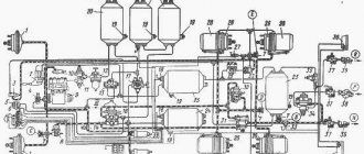
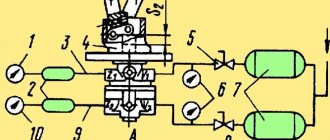
Checking and adjusting the combined brake valve.
Each repaired and assembled brake valve is tested on a pneumatic installation made according to the diagram shown in Fig. 12-24. The air pressure in tank 3 must be equal to 0.7 MPa (7.0 kgf/cm) and maintained for the entire test period. Air should be supplied to the inlet valves of the faucet.
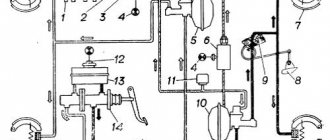
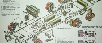
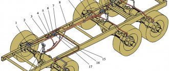
brake valve drive
Fig. 12-23. Brake valve drive for vehicles with single-circuit drive:
1— thrust of the foot drive of the crane; 2- cover; 3- lever; 4 and 5 - adjusting screws; 6 - rod for manual drive of the trailer crane; 7 and 11 — locknuts; 8 and 12 forks; 9 and 13 - fingers; 10 - handbrake drive lever; 14- intermediate lever; 15 — pedal thrust; 16 — brake pedal; 17 – cabin floor; 18— tension spring
test scheme
Rice. 1 2-24. Diagram of the installation for testing a combined vehicle brake valve: 1 - brake valve under test; 2, 5 and 7 - pressure gauges; 3 - air tank with a capacity of 20...25 p; 4— pass-through valve; 6 and 8 - air tank with a capacity of 1 liter; 9 - three-way valves; 10 — control lamp; 11 - current source; 12 fuse 5 A; 1 – from the air source
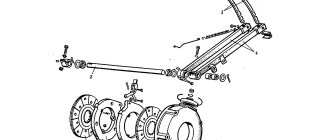
Operation of the central braking system ZIL-130
The wheel brake system has a housing mechanism with a hole; a rubber diaphragm with fabric is clamped between them, which rests on washers. A connection nut is screwed onto the surface of the rods and secured. The fitting on the cover is connected to the brake valves, the cameras are attached to brackets next to the disc. The wheel brake system at the front is connected to two cast iron pads with linings. The block is tightened by a spring and installed on the support pins, which are attached to the brake shield. On the outside there is a brake cam between the block, and the shaft is installed in the shield brackets.
The rear brake has a profiled pad; one end rests on the eccentric pin, but does not completely grip it. The reverse side is equipped with rollers that press the block against the release elements.
Wheel braking system
The brake valve combines, ensures the process of controlling the mechanisms of the machine, installation is carried out for the working process with a trailer. Two tanks are installed in the main building, the entire control process takes place below, and at the top the action occurs due to the trailer brake.
The lower container has a body part and lids; the mechanisms are secured with rubber diaphragms. The covers contain an inlet valve, which is secured by a release spring.
The air cylinder wire is connected to the plug hole, and the wheel brake wire is connected to the side of the plug. The cavities in the passages with diaphragms communicate atmospheres through the windows, which are supplied with valves.
The crane at the top is controlled by the trailer brakes and works on the same principle. The springs are attached to rods that are installed in the mechanism direction sleeve. At the holes, thanks to fittings, air wires are connected from the reservoir to the sides opposite the valve.
In the covers, the base lever is connected along the axis at the front. The ends at the top of the device are connected thanks to the traction of the pedals. The draft is closed from the taps by the sealing mechanism of the cover, which is fixed to the covers from above. The bottom end of the levers goes into the cutout of the passage; a brake light sensor is attached to the taps.
The process of transition from a brake valve to a full-fledged system occurs according to the following principle:
- If the brake pedals are not pressed, the volume intake mechanism at the bottom closes and the exhaust mechanism opens. The brake chamber of the car is disconnected from the air reservoir and connected to the atmosphere through the outlet window. The brake does not respond.
- The upper volume of the exhaust valve is closed, and the intake is open, which is why compressed air penetrates. The brakes that operate when the pressure in the connection line drops are released.
When the brake pedal is pressed, the main lever should turn and move the section rod from top to front. The glass of the section from below, thanks to the small lever, goes into the background. The diaphragm in the socket below will move. This will close the exhaust valve and open the intake device. The brake wheel chambers of the car are separated from the air, and a compressed atmosphere is supplied. With this action, wheel braking occurs.
It happens that the pressure in the brake of a car exceeds the corresponding values that are available by pressing the pedals. This is why the diaphragm moves forward and passes the resistance of the valves, which close. This stops the supply of compression air.
Under the operation of the levers from above, the rods move forward and the springs are compressed. During the process, the intake valves close. If there is a breakdown under the influence of the air distributor that is installed in trailers, the brake will be in operation. If the pedal is released, the machine will stop braking.
On modifications of ZIL-130 vehicles that do not work with a trailer, single brakes with passage are installed.
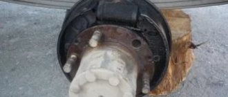
Manual brake center
It is a block type. The cast iron brake device is mounted at the rear. There are 2 blocks in the drum shell, the axis of the mechanisms is fixed to the support bracket. The pads are regularly tightened by springs and released when the brakes are applied.
The cam shaft is installed in the support brackets, the levers are connected to the drive due to gravity. In this case, the process immediately performs braking work on the machine. The lever is equipped with locking latches that move in sectors, and control comes from the handle. This method will allow you to secure the levers, even if there is a braking condition.
Adjustment of the brake by hand occurs by rearranging the fingers with connecting rods in the hole of the shaft levers. Both processes are different, but have some similar mechanisms when braking on a car.
Disassembly and assembly of a combined brake valve.
To disassemble the tap, unscrew the cover together with cover 2 (see Fig. 12-22) and disconnect the tap drive rod 1 from lever 3, then remove the cover. To remove the lever housing, unscrew the bolts securing the lever housing to the valve body 8. If necessary, remove the roller with cam 25 and the axle with small lever 29 from the lever body by pressing it out of the lever body.
To remove the large lever 3 from the rod 7, it is necessary to press out its axis and remove it together with the rod 1.
brake valve
Fig. 12-22. Combined brake valve with single-circuit brake actuator:
1 — brake valve drive rod; 2 — protective cover; 3 - large lever; 4 — stop of the large lever; 5 — spring of the equalizing section that controls the trailer brakes; 6 — rod guide bushing; 7 — rod; 8 — body; 9 - membrane; 10 and 17 — exhaust valve seats; 11 O-ring; 12 and 18 — exhaust valves; 13 — adjusting shims; 14 and 19 — intake valves; 15 — intake valve seat; 16 - cover; 18 - cover; 20 – membrane of the brake signal switch; 21 — contact connecting plate; 22 — contact spring; 23 - clamps of the brake signal switch; 24 - moving contact; 25 — switch body; 26 — channel for supplying compressed air to the brake signal switch membrane; 27 — balancing spring of the section that controls the trailer brakes; 28 — balancing spring cup; 29 — small lever; 30 - lock nut; 31 — rod stroke limiter; 32 — shaft of the manual drive lever; 33 — lever connected to the parking brake drive; 34 — stop of the manual drive lever. The arrows indicate the direction of air movement: A - in the line of the trailer; B - to the brake chambers of the tractor; C - from an air cylinder; D - into the environment.