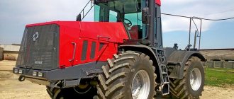
Tractor K744 "Kirovets" - Technical characteristics
To cultivate large volumes of agricultural land, high-power tractors are used. One of them is the domestic tractor K 744. One such tractor cultivates up to 5,000 hectares of land in one season. The machine is used not only in agriculture, but also in other fields of activity. Using the K 744 tractor, you can clear snow from coverings, tow heavy loads, etc.
Advantages and disadvantages
The heavy weight of the machine is not only an advantage, but also a disadvantage . During agricultural work in the fields, its weight destroys the soil layer. In addition, it has a heavy engine located in front. Therefore, when turning without a trailer, it may overturn. But a modular machine has many more advantages When special modules are connected, the K 703 MA tractor becomes a welding unit, a rotary milling snow blower, and a vibratory roller. Given the necessary module, this universal wheeled machine can perform all kinds of work.
Basic gearbox faults
Malfunctions and breakdowns in the gearbox in most cases arise as a result of wear and tear of the components available here and individual spare parts. Signs of when a gearbox repair on a K 700 is needed:
- difficulty changing gears;
- spontaneous gear shifting;
- oil leak;
- jerks;
- knocks, noises from the side of the box.
In case of any of these manifestations, the owner of the Kirovets must conduct a general diagnosis of the transmission.
Difficulty shifting gears may be the reason why the synchronizer brakes have become unusable. The cause of jerking may be due to loose fastenings. Also, adjusting the gearbox control drive can resolve the breakdown.
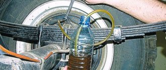
Repair of the K 701 tractor gearbox is necessary if increased heating of the installed gearbox is observed. As a rule, a low level of lubrication is noted in the gearbox. Fluid leakage from the drive axles occurs due to an increased oil level. Also, this may be the result of contamination of the breather. A consequence of the fact that the owner of the car has encountered a fuel leak may be worn out oil seals. Taking this into account, the tractor driver must monitor the oil level.
If insufficient pressure occurs in the hydraulic system, the gear coupling, roller, and bearing must be checked. It is worth inspecting the condition of the oil pump. If the pump has lost its performance, this element must be replaced with an option that will be suitable in its characteristics to the Kirovets working system.
Spontaneous gear shifting is another problem that can be eliminated by replacing worn parts or by adjusting the drive.
Driving the K 700 and other modifications will become more difficult if the gearbox pressure has dropped. There are several reasons for this, ranging from a clogged filter to a breakdown of the gear shift mechanism.
Not available:
| № | Part code | Name | Part Information |
| 744Р-3500170 | Air cylinder | Quantity on K-744R2 4 Model 744R Group Brakes Subgroup 3500 Serial number of part 170 | Not available |
| 744Р1-3500140 | Manual brake valve | Quantity on K-744Р2 1 Model 744Р1 Group Brakes Subgroup 3500 Serial number of part 140 | Not available |
| 744Р1-3500080 | Single Wire Actuated Trailer Brake Control Valve | Quantity on K-744Р2 1 Model 744Р1 Group Brakes Subgroup 3500 Serial number of part 080 | Not available |
| 744Р1-3500040 | Two-Wire Trailer Brake Control Valve | Quantity on K-744Р2 1 Model 744Р1 Group Brakes Subgroup 3500 Serial part number 040 | Not available |
| Kr20-3520010 | Tap | Quantity on K-744R2 3 Model Kr20 Group Brakes Subgroup Disconnect valve Serial number of part 010 | Not available |
| 744Р1-3500010 | Accelerator valve | Quantity on K-744Р2 1 Model 744Р1 Group Brakes Subgroup 3500 Part serial number 010 | Not available |
| P00-3521010 | Connecting head type A | Quantity for K-744R2 1 Model P00 Group Brakes Subgroup Connecting head for air brakes Serial number of part 010 | Not available |
| 2765020-3500160 | Sleeve | Quantity per K-744R2 4 Group Seat device Subgroup 2765 Serial part number 020 Additionally Not interchangeable with a part previously released under the same number | Not available |
| 744Р1-3500017-01 | Pipe | Quantity on K-744Р2 1 Model 744Р1 Group Brakes Subgroup 3500 Part number 017 | Not available |
| 744Р1-3500017-02 | Pipe | Quantity on K-744Р2 1 Model 744Р1 Group Brakes Subgroup 3500 Part number 017 | Not available |
| 744Р2-3500100 | Pipe | Quantity on K-744R2 1 Model 744R2 Group Brakes Subgroup 3500 Serial number of part 100 | Not available |
| 744Р2-3500101 | Pipe | Quantity on K-744R2 1 Model 744R2 Group Brakes Subgroup 3500 Serial number of part 101 | Not available |
| 744Р2-3500304 | Pipe | Quantity on K-744R2 1 Model 744R2 Group Brakes Subgroup 3500 Part number 304 | Not available |
| 744Р2-3500330-1 | Pipe | Quantity on K-744Р2 1 Model 744Р2 Brake group Subgroup 3500 Serial part number 330 Additionally Not interchangeable with a part previously released under the same number | Not available |
| 701-1504065-2 | Hose | Quantity for K-744R2 3 Model 701 Subgroup 1504 Serial part number 065 Additionally Not interchangeable with a part previously released under the same number | Not available |
| 8282519066 | Tube DIN 73378-10x1 PA11РНL | Quantity on K-744R2 30 Note 6, 9 Group Cabin accessories Subgroup 8282 Serial part number 519 Additionally Not interchangeable with a part previously released under the same number | Not available |
| 8282519046 | Tube DIN 74324-15x1.5 PA12НIPНL | Quantity for K-744R2 1 Note 24 Group Cabin accessories Subgroup 8282 Serial part number 519 Additionally Not interchangeable with a part previously released under the same number | Not available |
| 744Р-3500080 | Traction | Quantity for K-744R2 1 Model 744R Group Brakes Subgroup 3500 Part number 080 | Not available |
| 744Р-3500090 | Traction | Quantity for K-744R2 1 Model 744R Group Brakes Subgroup 3500 Part number 090 | Not available |
| 2256010-3500023 | Fork | Quantity for K-744R2 1 Group Cardan shafts Subgroup 2256 Serial part number 010 Additionally Not interchangeable with a part previously released under the same number | Not available |
| 744Р-3500050 | Pedal | Quantity for K-744R2 1 Model 744R Group Brakes Subgroup 3500 Part number 050 | Not available |
| 744Р-3500110 | Roller | Quantity on K-744R2 1 Model 744R Group Brakes Subgroup 3500 Serial number of part 110 | Not available |
| 8938313200 | Double square with nut | Quantity for K-744R2 3 Subgroup 8938 Part number 313 | Not available |
| 8935017834 | Tee | Quantity per K-744R2 12 Subgroup 8935 Serial part number 017 Additionally Not interchangeable with a part previously released under the same number | Not available |
| 8935017874 | Tee | Quantity for K-744R2 3 Subgroup 8935 Serial part number 017 Additionally Not interchangeable with a part previously released under the same number | Not available |
| 8934017744 | Square | Quantity for K-744R2 11 Subgroup 8934 Serial part number 017 Additionally Not interchangeable with a part previously released under the same number | Not available |
| 8938904500 | Square with nut | Quantity for K-744R2 12 Subgroup 8938 Serial number of part 904 | Not available |
| 8931047732 | Adapter | Quantity per K-744R2 3 Subgroup 8931 Serial part number 047 Additionally Not interchangeable with a part previously released under the same number | Not available |
| 8931047752 | Adapter | Quantity for K-744R2 11 Subgroup 8931 Serial part number 047 Additionally Not interchangeable with a part released earlier under the same number | Not available |
| 8938034100 | Union | Quantity for K-744R2 43 Subgroup 8938 Serial number of part 034 | Not available |
| 8938034200 | Union | Quantity for K-744R2 13 Subgroup 8938 Serial number of part 034 | Not available |
| 8938034500 | Union | Quantity for K-744R2 1 Subgroup 8938 Serial number of part 034 | Not available |
| 8938034600 | Union | Quantity for K-744R2 3 Subgroup 8938 Serial part number 034 | Not available |
| 8930220094 | Stub | Quantity for K-744R2 2 Subgroup 8930 Serial part number 220 Additionally Not interchangeable with a part previously released under the same number | Not available |
| 8931047722 | Adapter | Quantity per K-744R2 1 Subgroup 8931 Serial part number 047 Additionally Not interchangeable with a part previously released under the same number | Not available |
| 8915030524 | screw | Quantity for K-744R2 12 Subgroup 8915 Serial part number 030 Additionally Not interchangeable with a part previously released under the same number | Not available |
| 8915030534 | screw | Quantity for K-744R2 18 Subgroup 8915 Serial part number 030 Additionally Not interchangeable with a part previously released under the same number | Not available |
Design and principle of operation
MTZ 82 brake system with mechanical drive and dry friction discs. Two working parts of the brakes are located in cylindrical housings on both sides of the transmission housing on the same axis of the driven gear of the main bevel gear with a differential on the drive shafts of the final drive of the tractor. By activating the mechanical drive, the brake mechanism stops the drive shafts of the left and right final drives of the transmission, stopping the movement of the machine.
Each brake element consists of a pair of cast-iron pressure discs and a pair of friction discs mounted on the sides. Friction discs are located on the splines of the drive shafts. The movement of the pressure disks is driven through a system of levers due to the rolling of expansion balls installed between the parts in inclined grooves. When you press the pedal, the balls roll in the grooves and run onto its rise, pushing the discs apart. The rotation of the drive gears is stopped as a result of the movement of the pressure disks, while the friction linings are connected on one side to the surfaces of the pressure disks and the other side to the stationary surfaces of the casing and cup. When you hold down the pedal, the balls run up to the rise of the groove as much as possible and rest against the shoulder, the friction discs are pressed against the surfaces, completely slowing down the rotation of the shafts. To ensure parallelism of the pressing planes, three grooves with balls are placed around the circle with a pitch of 120 ̊ or with five grooves with a pitch of 72 ̊. Return to the starting position is achieved by the force of three tension springs installed on a pair of pressure disks. The drive levers and pedals also move out of their working position due to the force of the spring.
In older MTZ 80 (82) designs, the role of the parking brake is played by a latch that holds the pedals pressed. The brake system of newer tractors is equipped with an additional brake drum that acts as a parking brake. The organ has a completely identical design, is installed on the right together with the standard brake on one axis and is controlled by a separate lever with a sector lock.
To synchronously control the brakes of the left and right mechanism, the drive pedals are paired with a jumper, and the clutch is disengaged before pressing the brakes. To perform braking when turning, reducing the radius, the drive pedals are unlocked to allow braking separately with the left or right body.
contents .. 1 2 3 ..2.2.
TRACTOR KIROVETS K-744. BRIEF INFORMATION ABOUT THE DEVICE
The K-744R tractor differs from the K-744R1 and K-744R2 tractors in its base, engine installation, frame, wing shape and the absence of front axle springs. The K-744R1/R2 tractors are unified among themselves and differ in the design of the motor part, radiator unit and hydraulic steering system. The K-744R3 tractor has an increased weight due to the installation of ballast, as well as a modified design and hood lining.
The tractors are equipped with a four-stroke eight-cylinder V-shaped engine:
- YaMZ-238ND5 – on tractors K-744R, K-744R1;
- 8481.10 – on the K-744R2 tractor;
- 8481.10-02 and 8481.10-04 - on the K-744R3 tractor.
At the customer's request, OM457LA engines (Daimler Chrysler) can be installed on K-744R2 K-744R3 tractors.
The engine is started by an electric starter. To facilitate starting at low temperatures, tractors are equipped with a pre-heating system.
The air purification system is dry, two-stage, combined, with dust suction into the exhaust pipe.
The K-744R3 tractors use an air cleaner with a higher dust capacity.
To reduce contamination of the air cleaner, K-744 series “P” tractors are equipped with an extended air intake pipe.
ATTENTION! This pipe must be installed on the tractor in such a way that the maximum height of the tractor does not exceed 4 meters from the supporting surface.
The engine cooling system is closed, with a compensation circuit, with forced circulation of coolant. To maintain optimal thermal conditions, diesel engines YaMZ-238ND5 and 8481.10 are equipped with an automatic fan control system. At the same time, on the YaMZ-238ND5 engine, the fan control solenoid valve is additionally equipped with a hexagonal screw for mechanically turning on the fan.
In emergency mode (if the valve solenoid fails), to force the fan to turn on, the hex screw must be screwed into the valve body all the way.
When the fan operates in automatic mode, the hex screw must be turned out all the way. The solenoid valve is located behind the fan drive pulley (under the generator).
ATTENTION! It is prohibited to fill the engine cooling system and heating system with water.
The fuel system consists of a fuel tank, a manual fuel priming pump, coarse and fine fuel filters, a fuel priming pump, a high-pressure fuel pump with an all-mode speed controller, an automatic fuel injection advance clutch, low and high pressure fuel lines and injectors. Gas exhaust system - with one muffler and connecting pipes.
The tractor transmission includes a semi-rigid coupling and a pump drive gearbox, a gearbox, a cardan drive, an intermediate support and drive axles.
A semi-rigid coupling and pump drive gearbox are used to transmit torque from the engine to the gearbox. The gearbox also drives the pumps of the hydraulic steering systems and the attachment.
The tractor is equipped with a mechanical control system for switching gearbox modes.
The gearbox is mechanical, multi-stage, four-mode, with constant mesh gears, with a mechanical drive for switching modes and hydraulic gear shifting without interrupting the power flow within any of the modes. Allows you to change the speed of the tractor, move in reverse, engage the rear drive axle, transmit torque to the power take-off mechanism (PTO), start the engine from a “tug”, and also provide steering pump drive from the wheels when towing a tractor with a faulty engine .
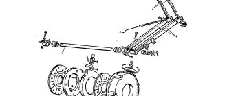
The cardan drive consists of a gearbox driveshaft, a front axle driveshaft, a rear axle intermediate shaft, an intermediate support and a rear axle driveshaft. The intermediate support connects the cardan shafts that transmit torque from the transmission transfer shaft to the rear axle.
Both axles of the tractor are driving and serve to increase the torque supplied to them from the gearbox and transmit it to the wheels. On the K-744R1 and K-744R2 tractors, the front drive axle of the tractor is suspended from the frame on two semi-elliptical springs with telescopic hydraulic shock absorbers. On the K-744R tractor, the front drive axle is rigidly attached to the frame. The rear axles of all tractors are rigidly attached to the frame.
Service brakes are dry, shoe type, with separate pneumatic drive on the front and rear wheels, installed in the final drives of the drive axles. The parking brake has a pneumatic spring accumulator combined with pneumatic chambers of the front axle. Both drive axles have wheels with low pressure tires. The K-744R tractors are equipped with 28.1R-26 tires, model FD-12; on K-744R1 tractors - tires 30.5R-32 model F-81 or 28.1R-26 model FD-12; on tractors K-744R2, K-744R3 – tires 30.5R-32 model F-81.
The tractor rotation control system is power driven.
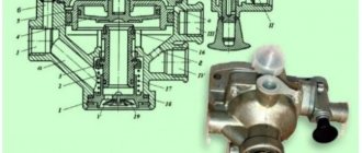
The tractor is rotated using two hydraulic cylinders due to the rotation of the tractor semi-frames relative to each other, around the vertical hinge. Proportional to the steering angle and rotation speed of the steering wheel, the supply of working fluid to the hydraulic cylinders is carried out by a metering pump
and
a flow amplifier
(on the K-744R2 tractor) or a hydraulic steering wheel (on the K-744R, K-744R1 tractors).
A gear pump or a pump with adjustable flow can be installed in the hydraulic system of working equipment on tractors. On tractors K-744R, K-744R1, a priority valve is installed to relieve the steering pump and additional supply of working fluid to the steering control system from the pump of the working equipment system.
Two pressure filters ensure cleaning of the working fluid supplied from the pumps to the hydraulic system components.
Diagrams of the hydraulic system of steering and attachments are given in Appendices 2, 2A and 2B.
The frame consists of two semi-frames: front and rear, connected by a hinge device. The semi-frames can rotate relative to each other around horizontal and vertical hinges.
The cabin is with a built-in protective frame, all-metal, two-seater, sealed, with heating, ventilation and air conditioning, with heat-absorbing tinted windows. The inside of the cabin is lined with thermal and noise insulating material.
The cabin has two seats equipped with seat belts. The driver's seat is sprung and adjustable in height, backrest angle, longitudinally and depending on the driver's weight.
The steering column has five fixed positions: a nominal position at an angle of 25° to the horizontal, three - every 5° from the nominal position when tilted forward and one - away from you. The tilt angle is changed by pressing the pedal located at the base of the steering column. The height of the steering wheel is adjusted with the flywheel located in the center of the steering wheel turned out 2-3 turns.
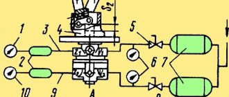
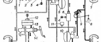
The pneumatic dual-circuit system ensures simultaneous operation of tractor and trailer brakes, manual control of trailer brakes when moving and when parked, parking brake drive, control of the pneumatic system of trailers with single- and double-line drives, air bleed when towing another tractor, for inflating tires, for blowing the tractor, etc. In particular, the K-744R tractor is equipped with a single-wire trailer brake control system, as well as a manual trailer braking valve.
On tractors K-744R1, K-744R2, K-744R3, an additional (to single-wire) two-wire trailer brake control system can be installed.
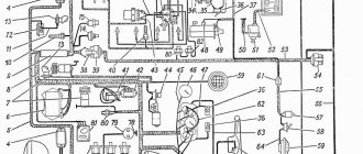
The diagram of the tractor pneumatic system is given in Appendices 1, 1A, 1B. The electrical equipment system is 24 V, single-wire, the negative terminals are connected to the tractor ground. The sources of electricity are two batteries and an alternating current generator working in conjunction with a voltage regulator. Electrical circuits of electricity consumers are protected from short circuits by fuse blocks. Tractors have the ability to connect to a 12 V power supply. The connection block is located under the cover in the lower right part of the instrument panel support next to the “12 V” sticker. The electrical diagram is given in Appendix 9.
The tractor is equipped with a separate hydraulic system and a three-point linkage, which serves to connect mounted and semi-mounted agricultural machines and implements to the tractor, adjust them in the working position and transfer them to the transport position. On tractors, a 4- or 5-section hydraulic distributor with remote cable control is installed in the hydraulic system of the working equipment; four sections of them (levers 2, 3, 4, 5) are designed for connection to external hydraulic lines.
The spool of the section with the regulator does not have an automatic return to neutral.
To reduce losses in the hydraulic system and prevent its overheating when working with seeders equipped with a hydraulic fan drive motor, the tractor spare parts kit contains a kit to ensure “free” (bypassing the hydraulic distributor) drainage into the hydraulic tank and a hydraulic motor drainage kit.
The free drain kit consists of a 2SN 20 DKOL 90/DKOL/3200 hose, an adapter 14/8-290/L18-22VDM (M30x2-M26x1.5), a breakaway coupling CPV082/2615F, a valve CNV082/2615M and two clamps 30-20- M8.
It is recommended to install a “free” drain kit when the hydraulic motor fluid flow rate is over 40 l/min.
Install the free drain kit as follows:
- remove the plug from the fitting of the hydraulic tank filter cover (right along the tractor);
- install hose 2SN 20 DKOL 90/DKOL/3200, fitting with 90° fittings, connect to the fitting of the hydraulic tank filter cover;
- fasten the hose to the rails “A” and “B” of the fuel tank using clamps 30-20M8, fasten the clamps to the rails with standard bolts. At the same time, in section “B” of the hose, provide “sag” (approximately 1000...1200 mm from the fitting of the hydraulic tank cover to the boom “A”) to prevent damage to the hose when folding the tractor around the vertical hinge;
- connect the fitting “G” of the sleeve through an adapter 14/8-290/L18-22VDM (M30x2-M26x1.5) with a breakaway coupling CPV082/2615F;
- connect the valve CNV082/2615M to the return route of the working fluid from the hydraulic motor.
The drainage kit consists of pipe 744Р2-4600010; clamping bolt 700.11.00.039, two copper gaskets 12M1, sleeve 2SN 10 DKOL/DKOL, L=3700, adapter 15-290/L1812 and coupling CPV082/2615F.
Install the drainage kit as follows:
- remove the M12 plug on the wall of the hydraulic tank on the cabin side;
- install pipe 744Р2-4600010 with bolt 700.11.00 and gaskets 12М1 on the tank boss;
- connect sleeve 2SN10 DKOL/DKOL, L=3700 to the pipe and lay it along the route, securing it to the sleeves with plastic clamps;
- connect the adapter and coupling to the free end of the sleeve. Connect the valve of the drainage route (leaks from the hydraulic motor housing) of the agricultural implement to the coupling.
ATTENTION! Only the hydraulic motor drain line (if equipped) should be connected to this route. It is prohibited to connect drain lines to it.
Installation of free drainage routes
A flow regulator is installed in one of the sections of the hydraulic distributor (the section handle is farthest from the operator). The adjusting screw of the regulator is located in the upper part of the section, in front (along the tractor) of the spool (see figure below).
The position of the adjusting screw “turned all the way” corresponds to the maximum value of oil flow through the section to the rightmost (along the tractor) pair of quick-connect couplings for remote hydraulic lines; the position “turned all the way” corresponds to the “0” flow rate.
To avoid overheating of the hydraulic system, you can use the flow regulator only when the tractor is equipped with a pump with adjustable flow. When the system is equipped with a non-regulated pump, the screw must be turned out all the way.
Hydraulic distributor (top view)
To connect the corresponding hydraulic lines of the hydraulic system of an agricultural machine or implement mounted with a tractor to the remote hydraulic lines of the tractor, and to prevent oil leakage from the high-pressure hydraulic hoses when they are disconnected or in an emergency rupture, three pairs of quick-connect bursting devices are designed (Fig. 25). To reduce peak loads that occur when switching the hydraulic valve spools of the working equipment, a hydraulic accumulator and a safety valve are installed in the tractor hydraulic system (in the “pump - hydraulic distributor” path) (Appendices 2 and 2A). The hydraulic accumulator is a sealed vessel under high pressure.
ATTENTION! The hydraulic accumulator is not subject to maintenance, disassembly or repair. Do not carry out welding, soldering or mechanical work on the battery case. Welding or soldering may cause an explosion!
Mechanical impacts on the housing can lead to damage and loss of functionality of the accumulator. Pay special attention to the need to perform installation and dismantling work in the hydraulic system only when there is no pressure in it.
For external lighting and signaling, the tractor is equipped with two transport headlights with high and low beam, eight working light headlights, four turn indicators, four side lights, a “road train sign”, two side turn indicator repeaters, two “Stop light” lights.
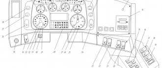
Hydrostatic steering control of the tractor, an angle- and height-adjustable steering column, and an instrument panel with automatic control over the operation of the tractor systems greatly facilitate the driver’s work.
contents .. 1 2 3 ..
How to check and adjust brakes
There are clear instructions for checking and adjusting the brake system of a bicycle. If you adhere to it, the whole process will take little time and will be effective.
Procedure for checking and adjusting the brake system of a bicycle:
The setup of the brake system is different for rim and disc types, as different rotating mechanisms and pads are used.
Setting up rim brakes
Mountain bikes use a v-brake braking system - using its example, we will consider the principles of adjustment, since it is also available on other bicycles with rim brakes. The only difference may be a different arrangement of bolts and screws that will need to be tightened/tightened.
Modifications
Kirovets K 744р2 is available in 2 main modifications - standard and premium, this allows everyone to choose the right solution taking into account personal preferences. They differ in technical characteristics, as well as the type of installed equipment.
The standard equipment is equipped with a TMZ engine with a power of 350 hp. The “Premium” modification is equipped with an engine from the German automaker Mercedes, which has a power of 354 hp, is of excellent quality and a high degree of reliability.
At the request of the customer, various additional options can be installed on the device, which can significantly expand the capabilities of the tractor. Among them:
- a set of tracks, wide-profile tires or a set for doubling wheels;
- mechanism for power take-off;
- a set designed for successful cultivation of fallow land;
- various types of coupling devices.
The optional precision farming system makes work much more efficient.
The tractor has a cabin with excellent visibility