In April 2010, the company decided to revive the production of the legendary UAZ by releasing a limited batch of the UAZ-469 model, dedicated to the 65th anniversary of the Victory. Over the entire period of production since 1972, the UAZ-469 has established itself as a trouble-free SUV that can be used in almost any conditions.
One of the facts noted in the history of UAZ: in August 1974, three completely standard (without winches and traction chains) UAZ-469 vehicles, during a test run, reached a glacier on Mount Elbrus at an altitude of 4200 meters. It can be recalled that this car is the heir to the famous GAZ-69 model, previously produced by the Gorky Automobile Plant from 1952 to 1972, after which production of the already updated UAZ-469 model was moved to Ulyanovsk. In 1985, after modernization, the SUV received the index 3151, under which it was produced until 2003, when production was suspended due to the appearance of the improved UAZ Hunter model. Actually, the revived 469 was created on the basis of Hunter and uses its main developments - spring front suspension, disc brakes, power steering, etc.
Main technical characteristics of UAZ 469
469 469B
| Weight without load | 1600 kg. | 1540 kg. |
| Full load weight | 2400 kg. | 2280 kg. |
| Fuel tank volume | 78 l. | |
| Drive unit | Fully pluggable | |
| Highest speed at full weight | 90 km/h. | 120 km/h. |
| Control fuel consumption at a speed of 30 km/h. | 10.6 liters / 100 km. | |
| Highway range at reference consumption 10.6 l/100 km | 730 km. | |
| Braking distance with full load from an initial speed of 70 km/h | No more than 44.8 meters. | |
| Fording depth | 0.7 meters | |
| Maximum gradeability with driver and 1 passenger | 57 degrees | |
| Maximum gradeability when fully loaded | 31 degrees | |
| Maximum gross weight of towed trailer | 760 kg. | |
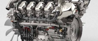
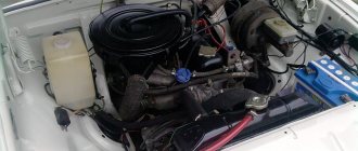
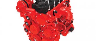
Engine
The UAZ 469 has a 4-cylinder engine of the UMZ 417 series with a volume of 2.5 liters.
The power of such an engine reaches 75 horses, the valves are located at the top. The fuel supply system is forced. Closed cooling system, liquid with forced circulation. The nuance of this engine is quite decent fuel consumption, up to 16 liters per hundred. Two different modifications of this engine are installed on the UAZ 469 for two different purposes. UMZ 4178 - for ordinary civilian models, UMZ 4179 - for military ones. The difference between “military” motors is that they are equipped with a distribution sensor and high-voltage shielded wiring. In addition, they have a special place for heating.
A distinctive feature of the UMZ 417 series engine is the special design of the combined cylinder block and the upper part of the crankcase into a single unit, made of high-strength aluminum alloy. The cylinders are wet removable liners and are cast from gray cast iron. The wear resistance of the liner is ensured by acid-resistant cast iron in the upper part.
The cylinder head is common to all cylinders and is made of aluminum alloy, just like the pistons. The five-bearing crankshaft is made of magnesium cast iron.
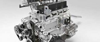
Transmission
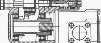
The UAZ 469 gearbox is used to change the torque from the engine through the clutch. The UAZ 469 gearbox converts the rotational energy of the crankshaft into forward motion of the transmission. Thanks to the four gears that the gearbox has for moving forward and one in reverse, energy is transferred to the wheels. The car can move in any direction. The UAZ 469 transmission is divided into two types according to the type of gearbox - old model and new model.
The old model UAZ 469 gearbox diagram is shown in the bottom figure. All the main spare parts for the UAZ 469 gearbox and gearbox components are clearly shown here. Products such as boot, oil seal, rubber seals are consumables and are replaced as they wear out. For the UAZ 469 car, the diagram is typical.
The gearbox in the UAZ 469 is attached to the clutch housing with four studs screwed into it. The drive gears of the intermediate shaft, second and third gears are made with helical teeth, the first gear - with straight teeth.
The gears are located on shafts and are in constant mesh. The gears of the first, second and third gears are mounted on the driven shaft on needle bearings. The drive shaft 1 has two supports. The front bearing is located in the crankshaft housing, the rear bearing is located in the front wall of the gearbox housing.
Fuel consumption
- Fuel consumption for the 2.4 engine is 15.6 liters per hundred kilometers, and for the 2.7 engine 10.6 liters per hundred kilometers.
- Gasoline consumption 92.
Bridges
One of the basic differences between the UAZ 469 and the UAZ 469B is the bridges. They can be military and collective farm, respectively.
Military bridges (UAZ 469)Collective farm bridges (UAZ 469B)
| Type | Detachable, with gearboxes on all wheels | Detachable |
| Gear ratio | 5,38 | 5,13 |
| Final drive ratio | 2,77 | 5,13 |
| Front axle weight | 140 kg. | 120 kg. |
| Rear axle weight | 121.5 kg. | 100 kg. |
| Volume of oil poured into each axle | 1 l. | 0.85 l. |
| Gear ratio of wheel reducers | 1,94 | – |
| Volume of oil poured into each gearbox | 0.3 l. | – |
Chassis
- suspension - rigid, leaf spring;
- springs - 7-9 leaf, elliptical;
- shock absorbers - telescopic, double-acting;
- wheels - steel, stamped;
- tires - tube;
- The recommended tire size is 215/90 R15.
Steering
- mechanism - worm type;
- gear ratio - 20-21;
- the volume of oil to be filled is 0.25 l.
Brake system
- type - hydraulic, drum;
- parking brake - transmission;
- liquid volume - 0.52 l.
UAZ 3151 Engine interruptions
The order of operation of the cylinders of the UAZ 469 engine 417
1. Start the engine and let it idle. Go to the exhaust pipe and listen to the sound of the exhaust. The sound should be even, “soft”, of the same tone. Popping noises from the exhaust pipe at regular intervals indicate that one cylinder is not working due to a failed spark plug, lack of spark on it, a strong air leak into one cylinder or a significant decrease in compression in it. Popping noises occur at irregular intervals due to improper carburetor adjustment, ignition, severe wear or dirty spark plugs.
Popping sounds from the exhaust pipe at regular intervals?
Yes: see point 3
2. You can try to replace the entire set of spark plugs yourself, regardless of mileage and appearance, but it is better to do this after contacting a car service center to diagnose and adjust the carburetor and ignition system.
3. Stop the engine and open the hood.
4. Check the condition of the ignition system wires. High-voltage wires must not have insulation damage, and their tips must not be oxidized.
Are the wires damaged?
No: see point 6
5. Replace the damaged wire.
6. Check the condition of the distributor cap and rotor. Unscrew the two screws securing the plastic distributor cover and remove it. Inspect the cover inside and out. There should be no cracks or carbon deposits on the cover, and the carbon contact should be damaged or worn. The rotor should not have cracks or burnouts. Replace faulty or questionable parts.
7. Remove the ends of the high-voltage wires and remove the spark plugs with a spark plug wrench.
Warning
When removing high-voltage wire lugs, never pull on the wire itself. Place your hand directly on the tip and twist it from side to side and then pull before removing it.
8. Carefully inspect the candles and compare their appearance with the photographs given at the end of the section. The gap between the spark plug electrodes should be 0.8–0.9 mm. If the candle is black and wet, you can throw it away.
9. If all the spark plugs look good, reinstall them and connect the high-voltage wires.
The operating order of the cylinders is 1–3–4–2, the numbering of the cylinders (1st, 2nd, 3rd, 4th) is made from the plastic casing of the timing belt drive. On the distributor cover, the number 1 indicates the 1st cylinder, then - counterclockwise, if you look at the cover from the side of the high-voltage wire sockets - the 3rd, 4th, 2nd.
10. Take a spare spark plug. Secure it to the engine in any way.
Warning
Do not fix the spark plug to the oil filler neck, oil dipstick, fuel pump, fuel hoses, or carburetor.
Reliable contact of the body or threaded part of the spark plug with the “ground” is optional, but desirable. Connect the high-voltage wire from cylinder 1 to the spare spark plug. Start the engine.
Has the engine trouble gotten worse?
Yes: see point 13
11. Replace the spark plug in the cylinder with a known good one. Attach the high voltage wire and start the engine.
Are engine interruptions still occurring?
Yes: see point 14
12. Have a nice trip!
13. Consistently repeat procedure steps 10–11 with all cylinders.
14. If, as a result of the measures taken, engine interruptions are not eliminated, contact a car service to diagnose the ignition system on a stand or diagnose the engine - measure the compression. Normal compression is more than 1.1 MPa (11 kgf/cm2), a difference of more than 0.1 MPa (1 kgf/cm2) in one cylinder indicates the need for engine repair.
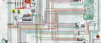
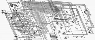
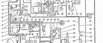
Scheme
- The length of the car is 4025 mm.
- The width of the car is 1785 mm.
- The height of the UAZ is 2015 mm.
- Ground clearance or clearance – 300 mm.
- The wheelbase of the car is 2380 mm.
- Rear track – 1442 mm.
- Front track – 1442 mm.
- UAZ weight 469 - 1650 kg - curb weight of the UAZ, 2450 kg - total vehicle weight.
- The vehicle's carrying capacity is 800 kg.
Cabin
A guide to replacing a distributor with an oil pump drive
The order of the cylinders of the VAZ 2114
Before installing a new distributor with a drive, you need to weigh your strengths, since it is not recommended to make mistakes when performing work.
So, how to replace and install the distributor:
- Turn off the ignition and remove the distributor cover; the tips and high-voltage cables are connected to it.
- Then you need to disconnect the wire connected to the switch from the distribution mechanism. You also need to disconnect the pipe connected to the vacuum regulator.
- Taking a 13mm wrench, unscrew the two nuts securing the device and remove the mechanism along with the oil pump drive from the power unit.
- After completing these steps, you will be able to see the gasket located under the drive. If as a result of these actions the position of the crankshaft has not changed, then simply install a new mechanism, making sure that the slider is located opposite the mark. All actions are performed in reverse order. When the installation is completed, the advance angle is adjusted.
- If, as a result, the location of the shaft has changed, then before installation it is necessary to move the piston of cylinder 1 to top dead center. You need to ensure that the marks on the pulley align with the pointer on the motor itself.
Principle of operation
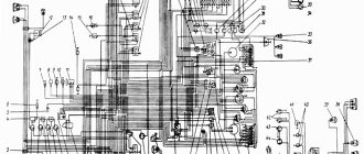
Adjusting the ignition of the UAZ 417 is a procedure that cannot be neglected. Starting the engine, operation and condition of the unit are components that depend on manipulation. Each engine cylinder is equipped with a spark plug, between the gap of which a spark is formed that ignites the fuel. Candles work in the required sequence, supplying a charge at the required time and with the required strength.
Without an ignition mechanism, the battery is powerless to produce the required effective electric field to ignite the fuel. This happens due to the lack of device parameters and the ability to generate a fixed current. Ignition increases the current, causing the fuel mixture to ignite.
Stages that take place before starting the power plant:
- Fixing the contact in the keyhole and further turning provokes the accumulation of electricity in the inductor;
- Processing of on-board voltage by the inductor into high voltage (from 12 to 30,000 V);
- Distribution and transportation of charge through car spark plugs;
- Producing a spark, igniting the fuel charge.
Ignition with missing contacts:
Engine ignition installation
An ignition device used in a power plant, a product without which the operation of the engine is impossible. The correct operation of the engine and the combustion of the fuel charge are directly related to how to install the ignition on the UAZ 421 engine. Since hydraulic valve compensators are not structurally provided, manual adjustment is carried out, providing:
- Installation of the shaft in accordance with the advance angle of five degrees. Align the middle marking of the friction wheel with the influx of the core plug on the compression in chamber “1”;
- Find out the compression stroke of the chamber “1” by removing the plug. In this case, the slider is located against the inner contact surface of the plug, connected by a conductor to the spark plug of chamber “1”. An alternative definition based on the candle in chamber “1” involves dismantling the product. The resulting void is closed with a paper plug, and then the shaft is turned. On the compression stroke, the plug will come out of the hole;
- Using the “tenth” key, slightly unscrew the octane regulator;
- Set the octane regulator calibration to “0”, corresponding to the middle of the calibration;
- Using the “tenth” key, slightly release the octane regulator plates;
- Align the rotor mark (red marker) with the stator arrow by turning the distribution sensor frame. Fix the location by tightening the fasteners;
- Check the position of the slider (against the contact of the plug of the 1st chamber), check the correct connection of the conductors leading to the chambers. The countdown starts from camera “1”, counterclockwise, in the order “1st, 2nd, 4th, 3rd”.
The ignition operation must be additionally monitored while driving the vehicle. Briefly press the foot speed lever to full speed, having previously accelerated the car to a speed of 60 kilometers per hour. Detonation for 1-3 seconds indicates that the settings are correct. Longer - the advance angle is exceeded, no detonation - the advance angle is insufficient. In the last two cases, the setting is repeated.