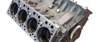
What is injection timing?
On diesel cars, it is more correct to call ignition the injection moment. It represents the beginning of the fuel supply when the piston approaches top dead center (the intake and exhaust valves are closed). Maximum pressure is created in the working chamber, at which point fuel is supplied.
How to set the ignition on a KamAZ? It would seem that it is worth adjusting it once at the factory when the car is released and not worry about it. However, not all so simple. The fact is that each power unit has a specific injection moment, due to the characteristics of the engine components. In addition, this indicator is influenced by the quality and type of fuel.
Settings
Any automotive power plant has marks (degrees) designed specifically for setting the ignition. If the system is adjusted strictly according to the marks, the engine will operate in optimal mode, provided that the injection pump, engine and fuel meet the reference characteristics according to GOST. By and large, the indicators are a kind of guideline that allows you to understand how to set the ignition on a KamAZ.
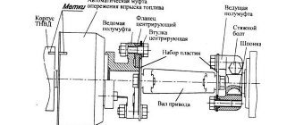
On the car in question, the high-pressure fuel pump is placed on a key on the side of the box, and the injection pump coupling can be fixed in two positions with a difference of 180 degrees. As a rule, if the drive pressure screw is located in the upper part, then the injection pump and clutch marks should be placed opposite.
content .. 21 22 28 ..
ASSEMBLY OF THE SECTION OF THE KAMAZ-740 ENGINE Injection Pump
Labor intensity - 21.0 people. min. 55. Install the rotating sleeve 10 of the plunger into the housing 14 (Fig. 5) of the injection pump section, install the sealing rings 12 on the housing 14 of the plunger pair, assemble the plunger pair and install it in the housing 14 of the section, install spring 20, plate 21 of the pusher spring. When installing a plunger pair, align the longitudinal groove of the plunger bushing with the lock of the section body; the plunger is installed with a mark on the shank towards the shut-off hole of the bushing. (Workbench).
56. Install the injection valve sleeve 16, sealing ring 2, valve seat 3, valve 4, adjusting washers 6, spring stop 8 into the body 14 of the section, screw in the injection pump fitting 9. (Spanner 19 mm).
ASSEMBLY OF FUEL PUMP FOR KAMAZ-740 ENGINE
Labor intensity - 86.0 people. min.
57. Screw in the studs 12 (Fig. 4) securing the injection pump sections into the injection pump housing. (Spiderman).
58. Install ball 37, valve guide 29, two adjusting washers 36, gasket 31 into valve body 28 (Fig. 1), screw in plug 32 of the bypass valve. The valve should be adjusted when testing the fuel injection pump. (Spanner 14 mm).
59. Install the screw with the gasket into the injection pump housing, screw the bypass valve assembly into the screw. (Spanners 17 mm).
60. Install washers 22 on cam shaft 21 (Fig. 4), press inner rings 23 of tapered bearings onto the cam shaft, install the shaft into housing 4. (Device for installing cam shaft bearings (Fig. 8)).
61. Press the oil seal 15 into the front bearing cover 14, press the outer rings 3 of the camshaft bearings into the covers 2 and 14 of the injection pump housing. (Copper hammer, mandrel D = 30 mm, L = 100 mm).
62. Install the sealing ring 13, adjusting shims 17, 18, 19 on the front cover 14, install the front 14 and rear 2 bearing caps into the injection pump housing and tighten screws 1 and 16. The free play of the cam shaft 21 should be no more than 0.1 mm . The free play is regulated by selecting the thickness of shims 17-19 under the front cover 14. (Phillips screwdriver, micrometer, tripod, indicator).
63. Install roller 65 (Fig. 1) on bushing 66, insert plunger 63 into pusher, press roller axis 68 into plunger pusher, press in pins 69, install cracker 67, insert pusher heel 64. (Hammer).
64. Install the pusher assembly 63, the installation pin 44 into the injection pump section, install the sections into the injection pump housing 9, lock washers 73, flat washers 75 and tighten the nuts 72 with spring washers 74 securing the sections. (Replaceable head 17 mm, knob).
65. Install washer 25 (Fig. 2) on axis 26 of the starting spring lever. Install lever 18 (Fig. 1) of the racks assembled with lever 24 (Fig. 2) of the starting spring, install spring 28 and pin the rack lever. (Pliers).
66. Install slats 5 and 77 (Fig. 1) and fix them. (Screwdriver 6.5 mm).
67. Install four rack bushings 24, tighten the locking screws 11 securing the rack bushing from the rear side in the housing (6.5 mm screwdriver).
68. Install O-rings 25 on plugs 24 of the slats and tighten plugs 26. (32 mm wrench).
69. Install thrust bushing 47 on the rear end of the cam shaft (Fig. 2), install drive gear 48, install two inserts 49 and four nuts 50 into the gear, press in key 51, install flange 52 of the drive gear, press in eccentric 53 of the fuel priming pump drive, install lock washer 54, tighten nut 55 and lock it by bending the lock washer antennae onto the edge of the nut. (Hammer, mandrel De„ = 18 mm Dnar=30 mm L=100 mm, chisel).
70. Install the retaining ring 42 into the intermediate gear 43, press in the bearing 41, install the spacer washer 44, press in the bearing 41, install the intermediate gear 43 on the idler gear axis 40, install the washer 45, tighten the nut 46 and secure it with a cotter pin 39. (Special pliers , bit, hammer, wrench 13 mm, pliers).
71. Install rollers on the weights, press in the roller axle 37 (Fig. 3), weight bushings 5, install weights 6 on the weight holder 3, press in the weight axles 4, install retaining ring 38 (Fig. 2) on the holder, install gaskets 13, Press in bearings 12, insert the weight holder assembly into the injection pump housing and install the retaining ring in the groove. (Hammer, mandrel Dvn = 31 mm Diar = 40 mm L = 100 mm, mandrel Dv = 18 mm Dn = 30 mm L = 100 mm, special pliers).
72. Screw two limiting nuts 37 onto the fuel supply adjustment bolt 36, screw the bolt 36 into the fuel injection pump camber, tighten the nut. The length of the fuel adjustment bolt inside the camber should be 55±0.2 mm. Measure from the bolt head to the outer plane of the body along the axis of the bolt. The gap between the pump housing and the limiting nut should be 0.8-1 mm. Carefully lock the bolt and stopper. The size determining the distance between the point of application of the main spring and the generatrix of the axis of the levers should be 52+0.5 mm. (10 mm wrench, ShTs-1 caliper).
73. Install the fuel supply corrector 27 (Fig. 3) into the regulator lever 36, the corrector spring 29, screw the corrector housing 30, screw the housing nut 31, install the washer 33, screw the fuel supply corrector nut 32 and secure with a cotter pin 28. (Spanner 22 mm, 10 mm, pliers).
74. Install the lever 12 of the fuel supply regulator on the thrust heel 10, press in the sleeve 18 of the levers, pin 14. (Hammer, mandrel D=6.5 mm L=20 mm D=8 mm L=60 mm).
75. Install weight coupling bearing 8, retaining ring 7, weight coupling bushing onto weight coupling 9, install the weight coupling into the camber of the fuel injection pump housing. (4mm screwdriver).
76. Install the remote bushing, lever axle washer, weight clutch lever 16, regulator spring 27 (Fig. 2), regulator spring lever 23 into the camber of the injection pump housing. (4.0 mm screwdriver).
77. Install the axis 26 of the regulator levers.
78. Install tube 1 (Fig. 3) for supplying lubricant to the weight holder, install gasket 11 (Fig. 2) of the rear cover 2 of the regulator, install cover 2 as an assembly, tighten screws 1 and 5 with spring 6 and flat washers 7 securing the rear regulator covers. (Screwdriver 6.5 mm).
79. Install two alignment pins 29, gasket 19 of the regulator cover with levers, cover 18 as an assembly into the injection pump body, tighten bolts 15 with spring washers 16 and 17 securing the regulator cover. Pin after testing. (Wrench, replaceable head 10 mm).
80. Install the fuel priming pump and tighten the nuts with spring washers. (Spanner 13 mm).
81. Install protective covers 15 (Fig. 1) of fuel injection pump sections, tighten screws 13 and 16. (8.0 mm screwdriver).
82. Press segment key 40 onto the cam shaft, install fuel injection advance clutch 33, tighten ring nut 35 with spring washer 34 securing the clutch. The tightening torque of the ring nut should be 100-120 N.m (10-12 kgf.m). (Hammer, device for removing, disassembling and assembling the fuel injection advance clutch, torque wrench mod. PIM-1754).
83. Remove the injection pump from the device for testing and adjustments.
TECHNOLOGICAL CARD No. 2.2. DEFECTIVENESS OF PARTS OF THE HIGH PRESSURE FUEL PUMP (HPF) OF THE KAMAZ-740 ENGINE
Total labor intensity - 34.0 people. min.
Performer: mechanic for repairing fuel equipment \ 4th category
content .. 21 22 28 ..
Peculiarities
After all the parts are aligned to the marks, you need to tighten the fixing elements and start the engine. The car should start without problems the first time. If the truck does not start or white smoke comes out of the exhaust system, then the alignment is not done correctly by 180 degrees. You will need to unscrew the required parts and rotate them 180° and restart the engine.
If there are no marks or there are unnecessary marks, it is advisable to place the elements approximately in the middle of the adjustment marks. To understand how to correctly set the ignition on a KamAZ, it is necessary to take into account the signs of late and early injection.
Early injection point
With early ignition, the piston does not have time to reach the top point, and fuel already begins to enter the working chamber. The main signs of this moment:
- Rough motor operation.
- When you actively press the gas pedal, a characteristic ringing sound is heard, which intensifies as the temperature of the power unit rises.
- White smoke may appear from the exhaust pipe.
- There is poor traction.
- Fuel consumption increases.
Late ignition: signs
At a late injection moment, the piston moves down from top dead center, and fuel is just starting to flow, the ignition follows. Signs of a problem:
- The appearance of white smoke from the exhaust system. The later the ignition, the greater the amount of smoke observed.
- The motor does not rev up correctly.
- The operation of the power unit is observed to be too soft.
- When the gas pedal is smoothly activated, the engine begins to shake at medium speeds, and when the torque increases, this effect abruptly disappears.
- Fuel consumption increases, the engine heats up, and the truck pulls poorly.
How to set the ignition correctly on a KamAZ Euro?
The factory settings generally assume a slightly late injection timing. If it is necessary to adjust the unit towards early ignition, perform the following manipulations:
- The injection timing is set at the operating temperature of the engine.
- The drive is adjusted so that the mark is on top.
- Loosen the two fixing screws at “17”.
- You only need to rotate the injection pump coupling.
- To enhance early ignition, the drive rotates clockwise, and for late injection, counterclockwise.
Adjustments should be made literally millimeter by millimeter, with the obligatory tightening of the bolts.
Knowing how to set the ignition on a KamAZ, after setting it up, you should start the engine and check it. If the operation of the power unit does not suit the owner, manipulations with the settings are continued until a slight ringing noise appears when the gas pedal is sharply activated. After another small shift it will disappear, which will indicate that the required ignition timing has been reached. A correctly set injection point will allow you to achieve better traction and fuel economy, which is important when operating any equipment.
How to set the ignition on KamAZ 5320
How to set the ignition on a KamAZ
right?
Knowing how to set the ignition on a KamAZ with the use of small equipment and inventory, you can solve this problem even in the field. To do this, you need to understand the mechanism of operation of the ignition system, as well as the reasons why it may fail.
What is injection timing?
On diesel cars, it is more correct to call ignition the injection moment. It represents the beginning of the fuel supply when the piston approaches top dead center (the intake and exhaust valves are closed). The greatest pressure is created in the working chamber, at this moment fuel is supplied.
How to set the ignition on a KamAZ? It would seem that it is worth adjusting it once at the factory when the car is released and not worry about it. But it's not that simple.
The fact is that each unit has a certain injection moment, due to the characteristics of the engine parts.
In addition, this indicator is influenced by the quality and type of fuel.
Settings
Every car power plant has marks (degrees) designed specifically for setting the ignition.
If the system is adjusted strictly according to the marks, the engine will operate in a rational mode, provided that the injection pump, engine and fuel comply with the standard characteristics according to GOST.
In fact, the indicators are a typical guideline that allows you to understand how to set the ignition on a KamAZ.
On the car in question, the high-pressure fuel pump is placed on a key on the side of the box, and the injection pump coupling can be fixed in two positions with a difference of 180 degrees. Typically, if the drive pressure screw is located in the upper part, this means that the injection pump and clutch marks should be located opposite.
Peculiarities
After all the parts are aligned to the marks, you need to tighten the locking elements and start the engine. The car should start without problems the first time.
If the truck does not start or snow-white smoke comes out of the exhaust system, it means that the alignment was carried out in violation of 180 degrees.
You will need to unscrew the required parts and turn them 180 and restart the engine.
If there are no marks or there are excessive marks, it is better to place the elements approximately in the middle of the adjustment marks. To understand how to correctly set the ignition on a KamAZ, you need to take into account the signs of late and early injection.
Early injection point
With early ignition, the piston does not have time to reach the top point, and the fuel is already beginning to enter the working chamber. The main signs of this moment:
- Rough motor operation.
- When you actively press the accelerator pedal, you hear a corresponding hum, which increases as the temperature of the unit rises.
- White smoke may appear from the exhaust pipe.
- There is poor traction.
- Fuel consumption increases.
Kamaz 55111 setting the ignition and a little about the clutch
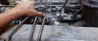
set the ignition
NOT BY HEARING, but by FUEL INJECTION.
We set fuel injection on KamAZ
Why not according to the mark when installing the ignition
(OVT)
KamAZ
.
Late ignition: signs
At a late injection moment, the piston moves down from top dead center, and fuel is just starting to flow, the ignition follows. Signs of a problem:
- The appearance of white smoke from the exhaust system. The later the ignition, the greater the amount of smoke observed.
- The motor does not rev up correctly.
- The operation of the power unit is observed to be too soft.
- When the gas pedal is smoothly activated, the engine begins to shake at medium speeds, and when the torque increases, this effect abruptly disappears.
- Fuel consumption increases, the engine heats up, and the truck pulls poorly.
How to set the ignition correctly on a KamAZ Euro?
The factory settings generally assume a slightly late injection timing. If it is necessary to adjust the unit towards early ignition, perform the following manipulations:
- The injection timing is set at the operating temperature of the engine.
- The drive is adjusted so that the mark is on top.
- Loosen the two fixing screws 17.
- You only need to rotate the injection pump coupling.
- To enhance early ignition, the drive rotates clockwise, and for late injection, counterclockwise.
KamAZ-740: how to set the ignition?
The injection timing is set simultaneously with the installation of the injection pump. The stages of work are given below:
- The cabin rises until the latch clicks into place.
- The flywheel housing rod is lifted and rotated 90 degrees and placed in a special niche on the housing.
- At the bottom, a pair of bolts are unscrewed and the dirt protection shield is dismantled.
- A metal rod with a diameter of 10 and a length of about 400 mm is inserted into the flywheel hole through the slot.
- The crankshaft is turned from left to right until its movement is blocked by the lock rod.
- The position of the injection pump drive shaft located in the camber of the cylinder block is checked.
- If the fuel pump drive coupling is turned with the operating scale up, align the zero point with the mark on the pump flange, and then tighten the two mounting bolts.
- If the position of the part is the opposite, lift the stopper, turn the crankshaft one revolution, and repeat the steps indicated above.
Now let's look at how to set the ignition on a KamAZ Euro-2 at the final stage. After tightening the bolts of the injection pump drive coupling, the stopper is lifted up, rotated 90 degrees, and lowered into the mounting groove. A dirt protection shield is mounted at the bottom of the casing. The car cabin is lowered, the clamps are placed in the upper position.
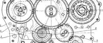
How to set the ignition on a KamAZ, diagram and adjustment rules
Turbocharged V-shaped Kamaz engines react very sensitively to setting the ignition timing. The mark on the high pressure fuel pump (HPFP) should be set in this way. So that fuel injection occurs 4 mm earlier, before the piston reaches top dead center (TDC). In practice, this can be accurately determined by placing a mark along the edge of the indicator arrow fixed on the injection pump. That is, if the engine is rotated along the way, and the mark is aligned with the peak of the indicator arrow, at this moment fuel is injected into the combustion chamber.
Then the mark continues to move, and at the moment of alignment with the edge of the indicator arrow, the piston reaches the TDC position at the moment of compression of the fuel in the first cylinder.
And now I would like to tell you in more detail how to do this in practice without error. The position of the piston at TDC is fixed using a stopper located on the flywheel housing.
But since in one revolution of the injection pump shaft the piston passes twice to the TDC position, and we need to determine the TDC position at the moment of fuel compression in the first cylinder. If you do not remove the high-pressure fuel pump, then simply move the mark on the injection pump coupling to the index arrow, release the stopper somewhere in this place, and rotate the flywheel in one direction or the other until the stopper fits into the groove of the flywheel. It is most convenient to rotate the flywheel using a lever, which must be inserted into the holes located in the end of the flywheel.
In this position, the piston will have the TDC position at the moment of compression of the fuel of the first cylinder. Having loosened the bolts of the injection pump drive coupling, align the mark with the edge of the index arrow. In practice, this position of the mark has been verified to be the optimal ignition timing angle. Shifting the mark in one direction or another leads to improper operation of the engine, it begins to smoke and develops poor speed. It is much more difficult to determine the position of the TDC of the piston at the moment of compression if the injection pump has been removed from the engine and needs to be reinstalled. The difficulty is to determine the TDC position of the piston of the first cylinder at the moment of compression. Since the crankshaft makes two revolutions per revolution of the fuel injection pump drive shaft, the piston comes to TDC twice, and we need the moment at which the fuel is compressed. You can, of course, remove the injector and plug the hole with a paper plug; the compression created in the cylinder during compression will push the plug out. At this moment, the stopper will fall into the groove of the flywheel, which will be the position of the piston of the first cylinder at the moment of fuel compression. But this method is not good enough, as it is time-consuming and labor-intensive. Personally, I go by the position of the valves. At the moment of compression, the valves become motionless until the piston reaches TDC, and after passing TDC, the valves are also closed. At the second position of the piston at TDC, one valve closes, and when passing TDC, the second valve begins to open. And to verify this, simply open the valve cover of the first cylinder.
In conclusion
Despite the fact that the diesel power unit has a simple and understandable design, the elements of its fuel system are considered high-precision devices. In this regard, the installation of a high-pressure fuel pump requires special attention and optimal determination of the angle of injection of diesel fuel through the nozzle into the working cylinder at the compression stage. Even an error of just one degree can lead to engine failure, which will require an emergency overhaul. Reliable KamAZ Euro trucks are popular in various areas. How to set the ignition on different modifications is discussed above. Knowing the features of this procedure, it is quite possible to adjust the timing of fuel injection on your own with minimal investment of time and equipment.
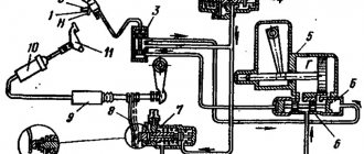
KAMAZ fuel supply system with Bosch in-line injection pump
1…8
- high pressure fuel lines;
9
— fuel drainage pipe of the left head injectors;
10
- nozzle;
11
— fuel drain pipe for right-hand injectors;
12
— fuel outlet pipe from the injection pump;
13
— fuel outlet pipe of the fuel priming pump;
14
— fuel pipe supplying the injection pump;
15
— electromagnetic valve EFU;
16
- FTOT;
17
— EFU spark plug;
18
— fuel pump;
19
— fuel pipe to the solenoid valve;
20
— fuel pipe from the solenoid valve to the EFU spark plugs;
21
- injection pump;
22, 33
— tee;
23
- valve;
24
— fuel injection pump bypass valve;
25
— retractor solenoid of the stop valve;
26
— fuel tank;
27
— filling neck with mesh filter;
28
— fuel intake pipe with strainer;
29
— fuel pre-filter;
30
— manual fuel pump;
31
— electronic speed controller of the fuel injection pump;
32
— reservoir of the PZD system.
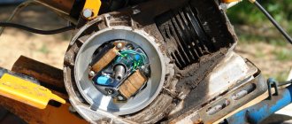
1
— fuel priming pump;
2
— minimum speed limit bolt;
3
— regulator lever;
4
— bolt for limiting maximum speed;
5
- stop lever.