The use of gas as a vehicle fuel provides a number of advantages, including:
- direct reduction in operating costs, which determines lower gas costs;
- noticeable reduction in engine wear due to greater gas resistance to detonation;
- reduction of environmental load by reducing emissions of harmful combustion products.
The disadvantages of gas engines (difficulty starting, reduced power, risk of explosion, reduction in trunk volume due to the installation of a cylinder for storing a supply of liquefied gas) are not significant with the current level of technology. Under such conditions, the number of supporters of installing gas-cylinder equipment is rapidly increasing, which, based on the principle of dosing the gas mixture, is divided into six generations. The most widely used technology is from generations 2 to 4; the use of efficient electronic sensors of the 5th and 6th generations is still holding back their cost.
One of the problems when equipping a car with gas equipment is monitoring the fuel level in the cylinder. The cylinders are equipped with standard gas pressure gauges. However, the ease of use of the vehicle dictates the need to move the indicator into the vehicle interior.
Design and principle of operation
Sensor design features
When using gas equipment, it is necessary to select a sensor.
The gas fuel quantity control device is based on a gas level sensor. The sensitive element of this device is mounted on the multi-valve of the gas cylinder, and the readings are reproduced by a regular or multi-color LED indicator. A number of older models of these devices provide more accurate dial indication or use a digital level indicator.
The similarity of the operating principles of these devices with a conventional fuel level indicator allows you to combine them, and the type of readings is selected using a switch.
Features of the gas indicator and choice of installation location
Gasoline and gas indicators show significant differences:
- for the most common analog devices, a full tank of fuel traditionally corresponds to the right position of the arrow, while for gas the picture is exactly the opposite;
- The range of changes in the resistance of a gas sensor corresponds to approximately half of that for a gasoline sensor.
When combining gas and gasoline level readings in fuel tanks, possible confusion while simultaneously increasing the clarity of the readings is eliminated by upgrading the instrument cluster. To do this, the fuel gauge scale of the standard instrument is supplemented with a blue sector so that it covers only half of its range. An example of the modification is shown in Figure 1.
Rice. 1. Combined petrol/gas level indicator on the analog dashboard of a passenger car
In the second case, a separate device is responsible for the gas level readings, which is embedded into the front panel in any convenient place.
The electrical diagram for connecting the individual blocks of such a combined device is shown in Figure 2.
Rice. 2. Connection diagram of gasoline and gas sensors to a common dial indicator indicating the fuel level
How to check how much gas is left in the tank
Without special instruments, the approximate remaining gas (methane or propane-butane) can only be determined experimentally (by mileage). After the cylinder is fully refilled, the speedometer counter (odometer) is reset to zero, and the car is operated exclusively on gas fuel until it is completely used up. After this, the distance traveled is recorded and the specific gas consumption is determined, which will serve as an indicator for further trips.
Obviously, the accuracy and ease of use of the above method leaves much to be desired for several reasons:
- the conscientiousness of the gas station attendants does not always meet expectations;
- influence of climatic conditions during movement;
- manner of operation of transport.
Therefore, to find out how much gas is left in the cylinder, it is wiser to take advantage of the fruits of technological progress.
Gas level sensor differences
The resistive or electromechanical type device is based on a magnet, which is rigidly fixed to the axis of the multivalve float and rotates with it. The use of such a scheme breaks the direct mechanical connection with the gas mixture, which has a positive effect on the operational reliability of the device. The rotary magnet interacts with the sector rheostat, i.e. As the gas level changes, the resistance of the circuit changes.
Resistive devices that are installed on a multivalve are structurally designed according to two- and three-contact circuits, which changes the organization of the connecting wiring.
In addition to resistive sensors, devices are available that implement other operating principles. Thus, a non-contact ultrasonic level sensor operates on the principle of sound location. In fact, it measures a linear quantity, which is then converted into volumetric units. The increase in the accuracy of the device is achieved by:
- acoustic vibrations in the ultrasonic range are used;
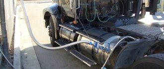
- the cylinders are placed horizontally;
- use only those sensors that are designed for a specific type of gas equipment.
The principle of ultrasonic location is implemented by the popular gaslevel sensor.
The manufacturer usually recommends sensors for working with a specific type of gas equipment. For ease of installation, the delivery kit is usually supplemented with fasteners.
Operating principle
There are several rules that must be taken into account when working with such a device:
- Depending on the amount of gas in the container, the float located in the middle of the gas cylinder changes its position.
- The method of interaction between the float and the gas indicator is mechanical.
- The indicator itself, as already mentioned, is located on the multivalve. This is where the signal comes from.
- The wiring is responsible for transmitting readings to the gas/petrol button. The button itself is located in the interior.
- The user will receive an indication when the button processes the readings.
For a multivalve, it is required to belong to class A and have a niche suitable for further installation of sensors. Another prerequisite is the coincidence between the resistance on the sensor and the switch at the same time.
Types of interior indicators
Several options for indicators of measurement sensors , the design of which is shown in Figure 3.
Rice. 3. Column and arrow gas level indicators
They are divided into:
- LED columnar;
- analog switches;
- digital.
The simplest columnar devices contain several LEDs. There are at least four of them: three green and one red. Green indicators indicate high, medium and low gas levels. The red diode turns on if the remaining gas is 10%.
Pointer and digital devices differ only in the type of scale. So-called methane pressure gauges contain a built-in microcircuit that outputs a digital signal in the required format.
Certificates
Technical regulation TS 004/2011 is where you can find the basic requirements for certification of devices such as measurement sensors. Devices that determine the gas level inside cylinders are no exception. A Customs Union certificate is issued if the equipment successfully passes the test.
Registration of the TP TC Declaration of Conformity is required for devices that are not subject to the normal regulations. This also applies to relays and sensors that do not fall within the range of 50-1000 V. To pass the tests, special events are organized with the participation of the appropriate laboratory.
Voluntary certificates also provide serious advantages over competitors.
Installation and connection of the sensor
Installing the device is not a big problem, since the manufacturer offers it as a kit. The factory equipment includes at least:
- the sensor itself with a sensitive element and an indicator;
- a connecting cable, the length of which is sufficient to carry the indicator into the car interior and install it in the dashboard or directly next to it.
The delivery set is supplemented with instructions that allow you to perform installation yourself without special knowledge and with minimal plumbing skills.
On HBO 2 generations
Devices for gas equipment of the second generation GBO-2 are optimized for propane-butane mixtures. The most widely used in practice are WPG-4, Apache, and AEB.
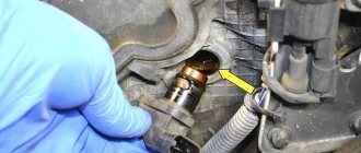
To measure the level with the popular WPG-4 sensor, its sensitive element is installed on a multivalve. The design of this sensor is shown in Figure 4. Installation is carried out strictly according to the instructions, be sure to check the tightness of the connections. Next, connect the wires to the indicator in the car.
Factory equipped WPG-4 sensor
Second-generation resistive devices allow for modernization, the purpose of which is to expand the range of current changes so that the full movement of the indicator needle when measuring fuel and gas levels coincides. This procedure boils down to changing the resistance of standard resistors and requires disassembling and some modernization of the printed circuit board. It can be performed correctly only when the car enthusiast has the skills to install electronic circuits.
On HBO 3 generations
Third-generation gas equipment differs from the second in that some of the control functions are performed by electronics. In terms of mechanical connections, these devices are identical. This feature is reflected in Europe: technology classified in Russia as the third generation is considered there to be one of the varieties of the second.
The most serious differences lie in the use of a stepper motor that controls the working mixture dispenser.
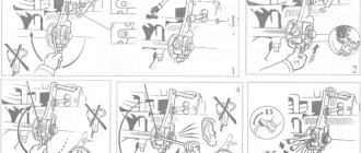
When installing 3rd generation equipment, it is necessary to make certain changes to the electrical connection diagram. Their essence is to enter into the controller a number of signals taken from a running engine. For this:
- The control electronics takes data on the qualitative composition of the mixture from the lambda probe;
- information for determining the amount of prepared working mixture is removed from the throttle position;
- Additionally, the sensor electronics receives data from the temperature and shaft speed sensor.
All collected signals are processed by the controller, which also takes into account the setting of the multivalve when dispensing the working mixture.
The electronics allow you to perform an emergency engine start using gas only. This mode is set manually.
The necessary connections depend on the sensor model and should be made according to the instructions.
On HBO 4 generations
The HBO 4 system and its version HBO 4+ are characterized by increased operating accuracy due to changes in control algorithms and more complete collection of data on the current operating mode.
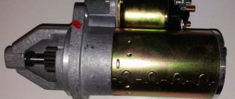
To install this system, it is necessary to install the sensor on the balloon multivalve. The design of the sensor is such that its connection does not cause serious problems. An example of its implementation is shown in Figure 5.
Figure 5. 4th generation GBO sensor type Torelli T3 Pro
The device can be equipped with a standard dial indicator, which is an independent device.
To increase ease of use, the signals taken from the LPG system sensor are output through the wires of the standard control cable to the interior indicator.
The connection is made strictly according to the manufacturer's instructions. There are no significant features from previous cases.
Summing up
It should be understood that for any generation of gas equipment, the gas level indicator will not be 100% correct. There are too many factors influencing the accuracy of the indication. This is the setting, sensor model, HBO generation, time of year. The accuracy of the display even depends on the cylinder - for a cylindrical one it is much easier to do than for a toroidal one.
But even if all interrelated distorting factors are excluded, even the most competent technician, using the best machine, will not be able to achieve correct readings from a low-quality device. Therefore, first of all, you need to choose a good device model from a trustworthy manufacturer.
The deputy proposed to abolish the transport tax
Electric vehicles are being produced and distributed around the world. What about in Russia?
Calibration
Calibration of sensors with an electronic control circuit is carried out by connecting their controller to the control computer and then entering the necessary constants into the internal memory of the latter (programming). During calibration, the indicator readings are adjusted so that their maximum corresponds to a full tank.
Calibration of column-type devices is often complemented by adjusting the red LED turn-on level. The controller is programmed so that its operation is accompanied by an automatic transition to powering the engine with gasoline. The latter was done for reasons of ensuring its stable operation and protection from sudden “failures”.
When upgrading a resistive type sensor, setting it up is complemented by selecting resistances to “stretch” the readings over the entire standard scale.
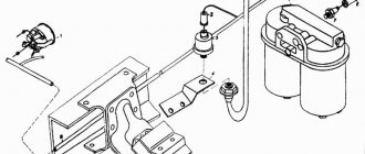
Where is it installed?
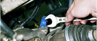
The gas pressure sensor is installed in front of the injectors and after the fine filter, which, in turn, is installed after the evaporator reducer. Why do experts recommend installing it after the fine filter? This is due to the fact that:
- firstly, the filter will help protect the sensor from clogging,
- secondly, after the filter is clogged, the sensor in front of it will show incorrect pressure. Incorrect readings will cause a lean mixture and unstable operation of the engine on gas. A lean mixture can also cause a popping sound in the manifold.
Another advantage of this installation option is the ability to control the filter clogging and the need to replace it.
Based on the readings of the gas pressure sensor, it is easy to determine a clogged gas filter.
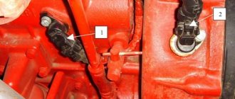
Learning to correctly diagnose MAP sensor PS-02
Many questions have always arisen regarding the MAP sensor when operating gas equipment.
A lot has been said and essentially nothing. The fact that the sensor does not work becomes clear when you connect the program and observe that in the program the pressure is either high or low and does not change. In this case, as a rule, the HBO does not turn on.
But no one ever finds out what caused the breakdown. Therefore, today I will tell you how to properly and inexpensively check the MAP sensor and, most importantly, determine what exactly is not working in it.
Since I have more than one sensor, I will describe the diagnostics of several sensors.
- We take several MAP sensors that are faulty or suspected to be faulty.
- We number them with a marker and enter them into a table indicating the signs of malfunction.
We disassemble the sensor housings. In this case, all sensors are disassembled by unscrewing 6 bolts. When removing the sensor board, we number it with the same number that was previously marked on the sensor body.
This will subsequently help us identify the board with the reported failures and correctly enter the measurement results. The most common defects in sensors that cause failure:
- Water on the MAP sensor
- Ash deposits on the pressure sensor (usually appear when gas filters are not properly replaced or when a MAP sensor is installed before the fine filter immediately after the reducer)
- Well, the most common and most destructive option for the sensor is oil deposits and this same oil getting inside the sensor
When we have figured out the markings and external features of the sensor, we open the MAP sensor diagram
Left row of contacts (sensor connector pins into which the HBO wiring connector is inserted) From top to bottom: Pin +12V, Gas temperature sensor Pin, Signal pin from the pressure sensor, Pin from the vacuum sensor, GND Pin The initial check of the sensor is to supply +12V power to 1 -th and 5th pins.
At atmospheric pressure and room temperature, the signal voltages are as follows: 1st pin - 12 V - input power to the sensor 2nd pin - 0 V - since it is a thermistor with variable resistance 3rd pin - 1.1 V signal from the pressure sensor (if the sensor is in good condition) 4th pin - 1.1 V signal from the vacuum sensor (if the sensor is in good condition) 5th pin - 0 V
If the indicated voltages correspond to those described, then the probability that the sensor is alive is 90%. Next, we take a disposable syringe, put a piece of vacuum hose on its spout and apply a pressure of 1 atm to the pressure sensor. In this case, the voltage on the 3rd pin rises to 2-2.1 V. After this, in a similar way, using the same syringe, we create a vacuum of 0.5 atm on the vacuum sensor - the voltage on the 4th pin drops to 0.5-0, 6 V
The voltages coincide with those described - the sensor is intact and working. But since we got into it, it means that there is something wrong in it and some voltages do not match and differ from the base ones. Legend of signals on sensor legs:
- If the voltage on the 4th leg of the pressure sensor is > 4 V, then there is a short circuit between the 2nd and 4th legs of the pressure sensor2.
- If the voltage on the 4th leg of the pressure sensor is 0 V, then there is a short circuit between the legs of the pressure sensor 3 and 4
- If there is a voltage >0 on legs 1,5,6,7,8, then there is a short circuit between legs 2 and legs 1,5,6,7,8
Reasons for failure
Sometimes the gas pressure sensor fails, and before replacing it with a new one or repairing the old one, you need to determine the causes of the failure.
The most common reasons include:
- For a non-separable sensor (type PS-01) – loss of housing tightness;
- Strong pressure surges in the line;
- Physical wear of the rubber seal of one of the sensors;
- Incorrect installation (upside down);
- Poor quality gas.