A mobile gantry crane is not a luxury, but rather a necessity. Especially if your workshop is large and has high ceilings.
But buying such an assistant is an expensive pleasure. It will be much cheaper to make it yourself.
In today's article we will talk about all the stages of creating a mobile gantry crane.
Necessary materials:
- profile pipe;
- I-beam;
- sheet metal;
- steel bushings;
- bolts with nuts;
- wheels with swivel mechanism and brake.
1
Operating principle of gantry crane
The principle of operation of a gantry crane is based on a set of cyclic operations associated with lifting piece or containerized material, periodically moving the unit from the place of slinging the material to the place of unloading, and back. Transportation of raw materials, structures and movement of equipment occurs thanks to a special mechanism - a cargo trolley. It ensures the vehicle moves along the bridge span.
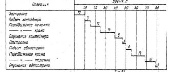
The main working operations performed by a gantry crane and their average duration:
- Capture. The load-handling device is inserted into the technological hole, which can be blind or through. The duration of the operation is on average 10-70 seconds.
- Climb. First, the load is raised to a height of up to 0.5 m so that the crane operator can verify the reliability of the fastening. When calculating the lifting time to a given height, the lifting speed of the holding device, acceleration and deceleration times, and lifting height are taken into account. The duration of the load lifting operation is from 25 to 50 seconds.
- Movement. The process time depends on the weight of the trolley, its carrying capacity and speed of movement, as well as the mass of the cargo load. The required time to move a trolley with a load is up to 20 seconds.
- Lowering. Depends on the height and speed of lowering, acceleration and deceleration of the load-handling member. According to a rough estimate, the duration of the process is from 15 to 30 seconds. It is allowed to lower the load only to the place provided for by the work project, where the tipping, falling or sliding of the transported elements is excluded.
- Releasing or unslinging cargo. Timing observations show that it takes 10-40 seconds to complete this work.
- Installing the hook in the upper position.
- Moving the empty cargo trolley to the zero position when the work is completely completed.
The set of technological operations for transporting cargo allows us to service large industrial facilities, while automating a number of production processes for creating finished products.
Under the crane console there is usually an asphalt concrete road on a crushed stone base. This hard surface is especially necessary in timber and heavy-duty warehouses where heavy trucks and tractors are used.
A crushed stone or gravel covering is made under the crane bridge, which creates better conditions for drainage of storm water. In some cases, at inactive stations, crushed stone and gravel coating is also used for the construction of roads, but at the same time it is surface treated with bitumen. The design of coatings for open warehouses is established by regulations.
To drain storm water, the crane platform has a transverse slope of 20°/00. Drainage pipes with outlets into roadside ditches are laid along the sides of the site at a distance of 8 m from each other. Wastewater is discharged into storm drains. In station warehouses where there is a closed drainage system, stormwater inlets are installed, from which concrete pipes are laid to the collector. The warehouse must be equipped with running water. The distribution water supply network is usually laid under the road.
Crane tracks. The paths for the movement of the crane should be located no lower than the level of the railway track and the crane platform. The rail threads are carefully straightened in the vertical and horizontal planes.
The construction and maintenance of crane tracks must meet the requirements of the Instructions for the construction and operation of crane tracks for gantry cranes with a lifting capacity of up to 50 tons, No. TsM 3955.
The crane track of a gantry crane consists of a subgrade, devices for draining water and elements of the superstructure: rails with fasteners, wooden or reinforced concrete sleepers.
For crane tracks, it is recommended to use new or repaired rails of the P50 type. The difference in vertical and lateral wear should not exceed 1 mm. Lateral influx on rail heads is not allowed (TU-32/TsP-1-76). Rails can be welded in a length of no more than 100 m using electric contact or another method that allows for the required strength of the seam. At least two 12.5 m long rails are laid between the long strands. The joint gaps must be at least 5 mm, but should not exceed 10 mm. The fastening of the rails to the sleepers is carried out using fastenings KB, K-2, D-2. On flat pads, the joints are placed along a square.
For laying crane tracks, wooden sleepers are used, made by sawing impregnated railway sleepers with the ends reinforced with wire or steel strip.
Crushed rocks, sorted quarry gravel, asbestos or sand ballast are used as ballast. In some cases, metallurgical slags are used that meet the standards for railway ballast materials. The layer of crushed stone laid on a sand cushion 150 mm high should not be less than 300 mm, and the shoulder of the ballast prism should not be less than 250 mm. Recommended diagram of sleepers 1840 PCs. At 1 km (step 540 mm).
At a number of stations, cranes are operated on a heavy crane track made on a reinforced concrete beam of a U-shaped profile with cross-sectional dimensions of 0.45 X 1.2 X 4.15 mm. The beam is laid on a crushed stone cushion 250 mm thick on a sand base of 150 mm (project No. 890 of Gip-promtransstroy).
To fix the position of the crane runway according to the design marks, two control benchmarks (metal piles at least 1000 mm long, 30 mm in diameter) securely fixed in the ground are installed at the beginning and end of the track. The same benchmarks are installed to control the position of the rail threads in plan and height. Benchmarks are placed on the outside of the crane runway at a distance of 1520 mm with an interval of 25 m.
In order to prevent transverse theft of the track, longitudinal wooden beams (logs) 2.7 m long are laid at each joint. The logs are attached to the sleepers on the outside of the track with two brackets. With welded rails, logs are laid every 6.5 m.
To drain surface and melt water from the ballast layer, drainage ditches are made or drainage pipes are laid every 20-25 m.
The section of track served by one crane is limited by limit switches. The 2.8 m long fender strips of switches are mounted at a distance of at least 3 m from the end of the track on the side of the crane trolley.
Limiting stops are installed at the ends of each thread of the rail track. A wooden shield with a sand prism up to 1.5 m long, at least 0.3 m high and 1 m wide or a piece of rail at least 1 m long welded to the end of the crane rail can be used as a stop.
The crane track is put into operation according to an act, the form of which is established by Instruction No. TsM 3955. The act is approved by the chief engineer of the railway department.
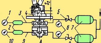
Current leads and grounding. Electricity to power the gantry cranes is supplied via cable or overhead trolley lines with a voltage of 380 V. The crane area is illuminated from the station's external lighting network with a voltage of 380/220 V.
Depending on the current supply method, standard feed columns (for cable power supply) or a trolley line (for trolley power supply) are constructed at the site.
Feeding columns are installed on the site from the side of the crane support (the support faces the railway track). Each column serves a section of the site 80-100 m long. To protect the cable located on the ground from contamination and mechanical damage, a plank trough or asphalt groove is installed along the crane runway.
When the crane moves, the cable is wound on a special drum located on the running trolley of support B (KKT-5 crane) or on the balancer of a flexible support (KKS-10 crane). Adjacent to the drum is a drive drum, on which a cable with a load is wound, sliding along special guides. Under the influence of the load, the cable tends to turn the drum, but this is prevented by the cable unwinding from the adjacent drum. As soon as the cable loosens, the weight will turn the drum and part of the cable will be wound around it again.
On sites longer than 100 m, it is advisable to use trolley power with a TF-85 contact wire, which is attached to the support using an elastic suspension (Fig. 80).
The suspension consists of a yoke, an earring draped over it, an insulator connected to the earring, rollers and a fork for attaching the wire holder. The suspension is held on the bracket by special clamps. The suspension links are hinged, as a result of which the wire holder can be moved both along the axis of the wire and in the transverse direction. This method of attaching the suspension to the support bracket makes it possible to adjust the position of the wires relative to the axis of the crane runway and the height of their suspension.
The distance between supports is usually 50 m; To prevent contact of trolley wires during wind, transverse inserts made of delta wood are installed in the middle of each span.
The wires are attached to the end support through a tension insulator and a rod to the channel, which in turn is held on the support with clamps. The position of the channel relative to the support and the tension in the wires can be adjusted using the thread of the tension coupling with a stroke of 300 mm.
The end fastening, like the intermediate fastening, allows you to change the position of the contact wires relative to the level of the crane track head. Clips are welded to the channel of the end support, into each of which, together with a round plate with a force of 500 kg, a compensator spring is inserted and closed with a pin. When the length of the contact line is up to 400 m, compensators are installed on both end supports.
Rice. 80. Intermediate support of the trolley line: 1 - reinforced concrete stand; 2 — traffic light; 3 — suspension; 4 — bracket with lamp; 5 - trolley wire; 6 — distribution box; 7 - box with switch
A buckle insulator can be used as a tension insulator. The wire is secured to the insulator with wedge-shaped end clamps.
The voltage from each wire is removed with a GT-14A rod current collector (Fig. 81), pressed to the wire from below by a spring. The current collector is equipped with a rod, which is connected to a pin through a pipe; the pin, in turn, is articulated with the base of the pantograph through a vertical axis. This connection ensures rotation of the rod when the crane moves along the contact wire. The base of the pantograph rod is isolated from the valve body with porcelain support insulators SA-6 or SA-3. A holder with a carbon-graphite insert is mounted on the trunnion.
To ensure reliable contact with the trolley wire, the insert is placed in a copper socket. Rotation of the clip on the axis ensures a tight fit of the insert to the contact wire along its entire length and prevents friction of the wire against the walls of the cartridge. The cartridge is loaded as follows: an insert is inserted into the socket from below, then the cartridge is inserted into a holder that holds it on one side with a protrusion and on the other with a screw; The same screw holds the tip of the wire running inside the tubular rod.
To replace coal inserts, a ladder with a platform protected by a shaft is installed on one of the intermediate supports. The inserts are changed twice a month with the voltage turned off.
On sites of considerable length, the trolley line is separated by sectional insulators. Thanks to this, it is possible to disconnect part of the line during repairs and supply voltage to some of its sections. To suspend the trolleys and the lighting network, reinforced concrete supports with a height of 12.8 m are used. Input boxes for the trolley line and lighting are placed on the end supports; Boxes must be locked. A three-pole switch with a removable handle placed outside and a 100 A automatic switch A-3124 are mounted in the input box Y-3120 of the trolley line. The horizontal trolley line does not require special thermal protection, since in the event of a break the wire is held by intermediate trolley holders or remote inserts.
Rice. 81. Rod-type current collector: a front view; 1 - tap; 2 — rods; 3 — suspension; 4 — current collector with graphite insert
The lighting of the crane area is arranged in combination: general - with 300 W SPU lamps, local - with floodlights on the crane. The illumination of the area where the crane is working must be at least 10 lux, and in the rest of the area - 5 lux. The lamps are installed at a height of 6.5 m at an angle of 20° to the horizontal plane. Some crane platforms are illuminated with xenon or mercury lamps.
Gantry cranes are grounded through the crane rails, so their joints must be securely connected. This is usually achieved by welding a steel strip with a cross-section of at least 48 mm to adjacent rails. The crane grounding diagram is shown in Fig. 82. To improve soil conductivity, a 2-3% solution of table salt is poured into the pipes. The grounding current spreading resistance should not exceed 4 ohms.
Instruction No. TsM 3955 defines the procedure for monitoring the grounding of the crane runway. The resistance to current flow is monitored with an MS-08 device, which is a magnetoelectric ratiometer with two frames, one of which is connected as an ammeter, the other as a voltmeter. The power source is a manually driven DC generator.
All equipment and structures on trolley line supports are also subject to grounding. Both threads of the crane track are connected every 50 m by jumpers made of round steel or strips with a cross-section of 48 mm2, and the rail joints are connected by jumpers made of round steel with a diameter of at least 8 mm. Ground loops are laid at the ends of the crane tracks. In addition, the crane rails are connected to the neutral wire of the three-phase current circuit.
Crane installation. Cranes should be delivered to the installation site only after all construction work at the crane site has been completed. In this case, the crane is installed quickly and without additional costs for temporary power supply, alignment and completion work.
Rice. 82. Grounding device for crane tracks: a - transverse section; b - top view
All components and parts are marked with oil paint in accordance with the general specification.
When the crane arrives from the manufacturer, they check the presence of seals, the integrity of the packaging, the completeness of the crane, the availability of tools, spare parts, and technical documentation in accordance with the invoice and packing list. The crane must have an inventory number and a technical passport, which is periodically filled out and stored as a document of strict accountability.
The crane elements are unloaded using a lifting mechanism (Fig. 83) and laid out on the installation site in the order of assembly. After unloading the components, a report is drawn up to check the completeness and condition of the crane.
Before assembling the tap, each unit should be thoroughly wiped and lubricated in the right place; fill the gearboxes with oil; to do this, unscrew the plugs on the crankcase covers and fill in oil to the level marked by the oil indicator tube or mark on the dipstick.
The crane is assembled in the order shown in the diagram with numbers and arrows. First, the bridge spans are installed on special trestles and on sleeper cages with a height of 2750 mm firmly connected with construction staples. Then they begin to assemble the supports: they connect the carts to the racks, insert the working bolts, tighten the nuts and cotter pins.
The completed support struts are lifted, their heads are brought to the corresponding hinge joints of the bridge. The heads of the racks are stitched with hinged rollers, which are then secured with crossbars. The running rollers of the support trolleys are installed strictly along the axis of the crane rail.
The platform and ladder are strengthened on the racks, the driver's cabin, the slinger's platforms and repair ladders are raised and bolted to the platform; install the counterweight in the guides, hang the drum, blocks, counterweight cable and begin installing the cargo trolley or hoist and electric drive devices.
Rice. 83. Layout diagram and sequence of assembly of elements of the KPB-10M gantry crane at the installation site: 1 - slinging site; II - removable platform; 111 - stand; IV - walking platform; V — rack bracket; VI - bridge; VII - rods of the hinge mechanism; VIII - portal; IX - balancer; X - cargo trolley; XI - cargo trolley beam; XII - resistance box; XIII - distribution cabinet; XIV - railings; XV - cabin; XVI - staircase; XVII — curtain pendant; XVIII - current collector
You should make sure that the electrical equipment matches the current and voltage of the power network, check the condition of the wires and windings of electrical machines and devices by measuring resistance. The insulation resistance must be at least 0.6 MOhm. This measurement should be performed by an experienced electrician. If the resistance is below 0.6 MOhm, it is necessary to dry the coils of the electrical devices of the brake magnets and the windings of the electric motors.
If the electric motor cannot be dried with hot air or external heating, use the short circuit current method. To do this, it is necessary to turn off the brake magnet and supply alternating current with a voltage of 16 V to the stator windings when connecting the windings in a triangle or 24 V when connecting in a star. During the drying process, the current passing through the windings should not exceed 1.5 V, and the temperature of the drum body should not exceed 160°C. To measure temperature, use a thermometer with a ball wrapped in plastic; The thermometer is installed in the hole of the locking screw in the middle of the drum.
The insulation resistance must be measured every 30 minutes of drying and at the end of drying. Drying is completed if the resistance does not change within 3 hours. It must be remembered that when drying with electric current, the motor housing (drum) must be reliably grounded.
There are several ways to install a hoist on the traveling beam of a KKT-5 (KD-05) crane:
the hoist is rolled without disassembly onto the riding beam from which the end buffer has been removed;
if it is difficult to free the beam from the buffer, remove the cheeks from one side of the running trolleys, lift the hoist and install it with rollers on the lower flange of the beam. After this, the cheeks are returned to their original place and the coupling bolts are secured with nuts;
The hoist is installed in parts: first, the running trolleys with a cross beam are mounted, and then the lifting mechanism is suspended from them.
The cargo trolley is lifted onto the spans of the KK-5 and KPB-10M cranes by a crane and secured with guy ropes under the portal.
The installation work of the KKS-10 crane has some special features. Consoles and truss sections are laid on sleeper cages with a height of at least 800 mm above the rail head. When installing section III, you must pay attention to the direction of the braces in accordance with the crane drawing. The section belts are connected to each other in all butt panels using corner and strip overlays on bolts.
Before installing braces in butt panels, you should check the straightness of the chords in the vertical and horizontal planes and carry out the necessary straightening. All braces are installed paired “crosswise”, except for the butt brace between the left console and the section. When welding, it is necessary to pay attention to the quality of the ceiling seams of the upper horizontal braces.
Simultaneously with the installation of the trusses, the monorail beams are aligned, joined together and attached to the truss. Longitudinal and butt welds on the traveling shelves of the beams are cleaned for smooth, shock-free movement of the cargo trolley. To install a lifting trolley, one of the beam sections is not joined. Rope blocks of trolleys are bolted to the end flanges of the monorail, oil supply tubes are installed with access to the surface of the deck, for which holes are drilled in it at the place where the tubes are installed. The trolley winch is inserted into the upper opening of the right console and installed. The middle of the winch drum must coincide with the axis of the truss. The winch support channels are welded along the entire contact contour.
The support strut is disassembled into two parts by bolting the intermediate flanges, and then the upper part of the support is hung on section I of the bridge using fingers inserted into the eyes of the struts.
To lift the top of the racks to the bridge flanges, driving and driven trolleys are used. Then install the installation locking mechanism. Four levers are attached to both sides and four half-strands of blocking rope with screw ties are hung. Each blocking rope is attached to an axle shaft welded to the rack channel. Then the rope is passed through the lever roller into the gap between the lever axis and its upper wall and secured with a screw tie to the axle shaft of another rack.
Lifting the crane. Self-assembly of the crane consists in the fact that the support columns, previously laid on the crane tracks, are tightened with assembly winches. Due to this, the bridge structure, under the action of vertical forces arising in the hinged joints with the supports, rises until the support plates of the bridge and the racks come into contact. This means that the crane has been raised to the required height and its elements can be fastened.
Before lifting, the electrical circuit of the crane is relieved of voltage by disconnecting the input devices. Then the installation winch ropes are stored in blocks of support trolleys or in mounting clips.
In Fig. 84 shows a diagram of the KPB-10M crane lifting, which is also typical for other cranes.
Before lifting, leveling devices of the hinge unit are installed, and on KPB-10M and KK-5 cranes, spacer bars are installed between the beams. It is strictly prohibited to install these cranes without spacer bars to avoid damage to the bridge.
On the winch side, thrust shoes are installed under the crane rollers and secured to the sleepers using crutches. Usually, LMC-3 winches are used for lifting, which are anchored strictly along the axis of each crane rail. For anchoring, sleepers are used, buried to a depth of 1.5 m and connected to the winch frame with rope ties. The KKT-5 crane can be lifted by a KDE-25 railway jib crane with an extended boom.
Rice. 84. Scheme of lifting the KPB-10M crane to working position:
Before you start lifting the crane, you must carefully check: the gap between the flanges of the running wheels and the rail, which must be at least 5 mm; fastening of leveling mechanisms; lubrication of hinges in the levers of leveling mechanisms and axes of pulley blocks; condition of the spacer bars between the main beams. Winches, their brakes, drives, the condition of the cargo rope and the reliability of its attachment to the winch drum are also subject to inspection.
Lifting is carried out on a platform at least 24 m long and 32-35 m wide. It is necessary to remove all foreign objects from the installation site; Attach the tools and parts required during installation to the crane structure. The gearboxes of the running support trolleys must be removed before installing the crane. To control the crane's lifting, it is recommended to mark the rails with chalk every half meter. The marks are placed on the side of the rail so that they are clearly visible to the installation manager. The crane should be lifted with stops to check the mechanisms, while adjustable shoes are constantly placed under the wheels of the moving stands. When rearranging the shoes, persons not involved in this operation are prohibited from being at a distance of less than 5 m from the dimensions of the crane that was unfolded before installation. During installation, the condition of the mechanisms and the uniformity of movement of the undercarriages are visually checked.
After the crane is fully lifted and the base is aligned, each pair of support trolleys is connected with bolts or crossbars to tie rods (balancers), and the support legs are bolted to the bridge. Pre-removed gearboxes are installed on the trolleys.
The KKS-10 crane bridge is lifted in two steps (Fig. 85). The support ties of this crane have flanged connectors that match the flanges of the trolleys. For preliminary lifting, the bridge is laid out across the crane tracks to a height of 0.8–1.0 m, and then the upper sections of the racks are hinged to the bridge. By simultaneously turning on the winches, the bridge is raised above the level of the supports by 100-150 mm and the fastening of the cables, pulleys, winches and anchors is checked. Particular attention is paid to the tension of the locking cables of the hinge mechanism. With normal cable tension, the longitudinal axis of the bridge is located strictly horizontally, and the supports are located along the axis of the crane tracks. Having ensured normal interaction of all mechanisms, the bridge is raised to a height of 5 m until the truss struts touch the support flanges. Sleeper cages or trestles are placed under the bridge.
A lifting trolley is hung onto the monorail beam through the gap left in the monorail. The cabin trolley is hung, which is connected to the cargo trolley via fingers; The last section of the monorail is welded and the joints are cleaned. The trolley must simultaneously rest on all rollers both on the monorail and on the guides. This is checked by test rolling the trolley along the beam. If gaps are found, it is necessary to adjust the support rollers by installing additional washers between the spacer tubes and the cheeks of the bogies. The support rollers are adjusted by installing spacers under their bracket. The normal position of the monorail bogies is fixed by welding two pieces of angle steel to the cheeks at the level of the upper row of tie rods.
The cabin is suspended from the transverse channels of the frame and secured with bolts and plates. Two brackets are installed on the right console, between which repair platforms are suspended. Ladders are installed on the platforms and welded to the truss elements. Cable trolleys are mounted on the monorail beam and a flexible cable is suspended. The cable garland in sections should form rings 4-5 m long.
Rice. 85. Scheme of lifting the KKS-10 crane: a - initial stage; b - preliminary rise; c - final rise
The running trolleys are disconnected from the upper sections of the supports and, together with the blocks of the pulley block, moved to a new position, the ropes of the pulley block are unraveled.
For the final lifting of the crane, it is necessary to connect the lower sections of the supports with the upper ones, using auxiliary hinges on the outer chords of the racks. After assembly, the supports are connected to the running trolleys and the tension of the locking mechanism cables is checked.
A platform is hung and bolted onto the flexible support of the crane, and a vertical ladder is welded to it. The final lifting is carried out by turning on the winches in the same sequence as during the first stage of lifting. The lifting of the bridge ends when the flanges of the supports come into contact with the braced trusses and struts. As soon as the crane rises to the design level, balancers (ties) are strengthened on the flanges of the support trolleys and the fastening work is completed.
If there are gaps, gaskets are installed between the flanges and struts of the truss, and then the units are connected with bolts and welding. After this, transition platforms, decking and other elements are installed and secured to the crane.
Installation work of all types of cranes is completed by refilling the cables and adjusting the mechanisms. Particular attention must be paid to adjusting the position of the running wheels. The position of the wheels in the vertical plane is adjusted using wedge spacers installed between the flanges of the supports and the running bogies. Adjustment of the position of the wheels in the horizontal plane is carried out by placing flat gaskets of the required thickness between the side flanges of the trolleys and the coupler. After installing mechanically driven rail grips, the interaction of their levers with the rail head is adjusted manually.
Checking the crane before commissioning. Before putting into operation, the crane is tested according to the program established by the factory. During testing, it is necessary to check the equipment, the state of insulation of electric motor networks, the compliance of electrical equipment with the type of current and voltage of the power network at the installation site, and the presence of lubricant.
The operation of the magnetic system of contactors and relays is checked by loosely pressing the contacts with your hand. When the force is removed, the contacts should freely return to their original position. Normally closed contacts fit tightly together when the device is turned off and open when pressed by hand. Overcurrent relays are regulated by 225% of the rated current of the protected electric motor, and for group relays - by 225% of the total rated current of the protected motors.
When checking electrical machines and devices, you should pay attention to the cleanliness of their elements, remove dust and excess lubricant. For motors with a wound rotor, check the tightness of the brushes; The rotation of the engine rotors must be free. Starting resistances are checked with a test lamp.
To check the limit switches, it is necessary to press the lever; the normally closed contacts open, and when the lever is released, the entire system returns to its original position.
The insulation of electric motors is checked with a megohmmeter up to 500 V with the ends of the windings disconnected. The test duration for each section of the motor winding is 1 minute, and the resistance must be at least 0.6 MOhm. When checking the insulation of motors, remove the strips connecting the star or delta windings and check each phase separately.
After testing the individual elements, the power cable is connected and testing of the crane under voltage begins. A poster “Live Crane” is hung on the tap.
Before testing the crane, it is necessary to check the fastening of motors, gearboxes and other equipment. Having climbed into the cabin and closed the entrance door, you should set the handle of the controller (command device) to the zero position, then turn on the switch of the protective panel, the emergency switch of the control circuit and press the start button. This turns on the contactor of the protective panel. If this does not happen, it is necessary to check the circuit and tightness of the contacts of the overcurrent relay, control contacts of switches, controllers and other devices of the control circuit of the protective panel.
The brakes are adjusted by tensioning the springs to the required braking torque, ensuring the braking distance specified in the crane's passport.
The next step is to check the self-shutdown. It is necessary to turn off the emergency switch, then the contactor of the protective panel will turn off. Having placed one of the controllers (command devices) in the 1st position and turned on the emergency switch, press the “Start” button, but the contactor should not turn on. This check is carried out with all controllers (command devices). Having finished testing the protection devices, they proceed to checking the crane movement mechanism. The motors must rotate when the controller handle or command device is moved to the 1st position. By sequentially entering new positions, the increase in engine speed is monitored. The engine take-off must be smooth.
By turning the handle of the controller (command apparatus), the engine of the lifting mechanism is started. If reverse movement occurs, the two phases of the stator are swapped. The operation of the limit switch is determined, and the stop must occur at least 200 mm before the extreme position of the holder.
On KK-5 cranes, the rope sensor is checked and adjusted. First, you need to tighten the main spring with a load of 10-20 kg using an adjusting nut, and each spring for adjusting the sensor stages until the coils touch.
To adjust the 1st stage of the sensor, lift the empty container using an automatic sling. The 1st stage adjusting spring is released to such a position that the head of the spring rod recesses the limit switch rod, i.e. that is, until the switch operates. Having lowered the container to the ground, check that the switch rod returns to its original position. The operations of raising and lowering an empty container are repeated two or three times, while ensuring the accuracy and reliability of the 1st stage of the sensor. After this, the adjusting nut is secured with a cotter pin.
To adjust the 2nd stage, a container weighing 6.3 tons is lifted using an automatic sling and, by releasing the second adjusting spring, the limit switch rod is pressed normally. After repeating the operations of lowering and lifting the load, making sure that the stage is set correctly, it is necessary to tighten the second adjusting nut.
The adjusted rope sensor is sealed by a safety engineer.
On KKS-10 cranes, the reliability of the rail grips is checked. The position of the limit switch located on the slide is adjusted so that the engine is turned off after compressing the spring by 20 mm. The rail grips close when the crane cabin door opens when the wind pressure alarm is activated, which corresponds to a speed of 12 m/s. In these cases, the warning lamp lights up and the crane movement mechanisms are turned off. If the wind speed exceeds 20 m/s, the wind pressure switch turns off all mechanisms and turns on an alarm.
To prevent wear on the flanges of the running wheels and the rail heads of the crane tracks, it is important to check that the support trolleys are installed correctly. The diameter of the crane running wheels should not deviate from the drawing by more than 0.5 mm. It is difficult to check this size at the site of operation, so use a measuring tape and measure the circumference along the wheel's rolling circle. The measurement is carried out strictly parallel to the wheel flange. The difference in the measured value on all four wheels should not be more than 1.3 mm.
The parallelism of the wheels is checked using a string, which is pulled along the support tie using a special device (Fig. 86). This device is nailed to the sleepers on each side of the crane and the string is adjusted with a screw so that it is parallel to the flanges of the front wheels, then the distance from the string to the surface of the second wheel is measured at two points located along the periphery of the circle. Non-parallelism of the wheels is eliminated by spacers between the flanges of the axle and the bogie and due to the gaps in the bolted fastening of the supports. They start by eliminating the mutual misalignment of the front wheels, then adjust the rear wheels.
To prevent the wheels from slipping, it is necessary to adjust the so-called electric shaft system, in which the speed of one engine must be equal to the number of revolutions of the other. To check, it is necessary to jack up one of the crane's running trolleys and measure the speed of the engines of this trolley with a tachometer while the others are turned off. This cart is turned off and the engine speed of the other cart is measured in the same way. The difference between the engine speeds at all speed control stages should not exceed 1.2%. The adjustment is made by selecting the starting resistances of the rotor circuits. All trolley gearboxes must have the same gear ratio.
Before putting into operation the crane must be registered by the Gosgortekhnadzor authorities. Permission to put the crane into operation is issued by the person responsible for safety regulations based on the results of a technical examination and control check by a representative of the Gosgortekhnadzor inspection.
Rice. 86. Device for adjusting the parallelism of support wheels
Technical examination of the crane includes inspection, testing and adjustment, static and dynamic tests. Static and dynamic tests are carried out in full compliance with the Rules for the design and safe operation of load-lifting cranes.
After technical inspection, the crane is run-in. Running-in includes the following operations: preparation for running-in, running-in of the crane without load, running-in of the crane under load. Preparing the crane for running-in involves checking the external fasteners and lubricating the mechanisms.
During the running-in period of the crane without load (at least 2-5 hours), the operation of the electric motors, instrument readings, the operation of the control panel handles, the absence of noise in the gearboxes, the operation of all components, brakes and electrical equipment are checked.
The crane is run in under load for 40–60 hours, first with a load of no more than 30% of the nominal load, then with a gradual increase in load to 70–80% of the nominal load. Run-in is carried out using the best quality oils; It is recommended not to change the filled lubricant until the end of the run-in, unless it darkens. By the end of the run-in, all mechanisms should operate smoothly, without jerking.
After the break-in is completed, it is necessary to change the lubricant in the gearboxes, inspect all fastenings and, after eliminating faults, draw up a report on putting the crane into operation.
During installation, technical examination or trial operation, deficiencies in the design or manufacture of the crane may be discovered, as well as non-compliance with the requirements of the Rules for the Design and Safe Operation of Load-Lifting Cranes. At the same time, the crane owner sends a complaint to the manufacturer, and a copy of the complaint report is sent to the Gosgortekhnadzor body.
Such complaints are necessary to eliminate shortcomings made by the manufacturer and to take measures to improve the design of the machine or its manufacturing technology.
Purpose of gantry cranes
Gantry cranes are designed to carry out work on transporting piecemeal, large and long cargo. These can be concrete building structures, timber, rolled steel, industrial profiles and products. Bulk cargo such as coal, crushed stone, sand is moved by crane in a special container.
Gantry cranes of various types have a lifting capacity from 3 to 50 tons with a span of 10-40 meters. Such multifunctional operating parameters allow the units to be used for various purposes: in shipbuilding, mechanical engineering, at railway stations and warehouses.
Gantry crane device
Features of the design and production of a gantry lifting machine are indicated by the current GOST 7352, issued in 1988. The design features of the main components and mechanisms of gantry cranes are determined by their purpose - transportation of heavy dimensional materials. Therefore, the unit is a reliable metal structure.
GOST 7352-88 Electric gantry cranes
1 file 702.15 KB
Support structure
The gantry crane base structure consists of a bridge of supports. Machines with two-post supports are most often used, as they have a greater load capacity. The support unit is made of flat or spatial trusses, or sheet box structures. One of the supports has a rigid connection, and the second one has a hinged connection to the bridge. If the distance between the crane rails is less than 25 m, then both supports are rigidly secured. In this case, the installation of equipment is greatly simplified, but pushing forces arise and there is a chance of thermal deformations. With this mounting scheme, the crane control cabin is mounted on metal supports and is motionless.
The bridge, depending on the design, can be single-beam or double-beam. The bridge is a spatial structure that consists of two trusses. Units with a single-beam bridge have a load capacity of 5-10 tons. In this case, the beam can be represented by a rectangular cross-section made of rolled steel or a triangular cross-section made of pipes.
The main beams of the gantry crane are fixed to the supports, and the load ropes pass between them. The cargo trolley moves inside the building. The structure of a single-beam span structure may have braces. Then the cargo mechanism moves in the upper part of the span, and the load is suspended from the crossbeam.
Lifting and moving mechanisms
In the case when the equipment is installed on a cargo trolley, vertical movement occurs along the beam chords. If the mechanism is located permanently on the bridge, then special conditions for reeving the hoisting winch rope are provided for movement. It passes to the block through the cargo pulley, and then to the end beam through the second block. With this scheme, the total weight of the unit is reduced by an average of 20%, due to the reduction in the weight of the bridge and the weight of the cargo trolley.
Cargo trolleys differ in load capacity, speed of movement and design, they can be:
- Monorails. They move along channels on bridge spans.
- Double rails move along the rail track or I-beam shelves. The rails can be located at the top of the main beams or on brackets.
- Self-propelled. The movement mechanism is located on the device itself.
- Cable cars. The drive for movement and lifting is located on the bridge. The movement occurs with the help of rope traction created by a drum and a winch.
To prevent the device from hitting the end beams of the gantry crane bridge, wooden or rubber buffers are installed - limiters in the places of the end positions of the load trolley.
The gantry crane is moved using a wheel drive located on supports. It is an asynchronous mechanism with a motor and a two-phase motor, which is connected to the wheels. The cranes are equipped with a braking device and an anti-theft grip.
Superstructure
The span of a gantry crane consists of box-section span beams with rails for the running rollers of the load mechanism. On the outer sides, at the level of the upper belts, the buildings are supplemented with platforms. The final elements of the spans are connected to each other by end beams and rest on columns - supports. To ensure the stability of such a unit, additional connections are provided to connect the columns.
Mini Gantry Manual Cranes
To work with small loads indoors and outdoors, lightweight mobile crane structures have been created - gantry manual cranes. They are used in small workshops, workshops, small indoor and outdoor warehouses. They are also used for loading industrial and agricultural goods, repair and installation work. They are especially useful for construction work in the field and repair of construction and agricultural equipment directly near the work area.
Typical design of lightweight manual gantry cranes
Manual mobile cranes are very easy to install by a team of 2-3 people within 30-45 minutes, practically without the use of special complex tools. They consist of 8 to 10 separate parts that are easily joined and secured with clamps, bolts or special locks.
A manual gantry crane consists of two vertical supports with braces, between which a horizontal beam is fixed. The main load-bearing elements can have different configurations. For racks, tubular or box-shaped structures, often of the telescopic type, are mainly used. An I-beam or pipe of round or rectangular cross-section is installed as a load-bearing bridge.
The choice of profile for supporting structures depends on the lifting capacity of the mobile crane and the scope of its use. It also depends on the type of lifting device used. They can be installed:
- Manual hoists;
- Electric hoists;
- Hand winches;
- Electric motors with gearboxes.
The side supports are installed on mobile carts equipped with swivel wheels. Wheels can be made from a variety of materials - rubber, metal, polypropylene, etc. Depending on the conditions of use, the size and type of wheelbase is selected. Most mini gantry cranes for warehouses are equipped with small wheels or carriages with wheel pairs, suitable for use on hard wood or concrete cast floors.
For outdoor work on tile or dirt surfaces, slightly larger pneumatic rubber wheels are preferable to make it easier to overcome possible unevenness.
Operation of manual mobile gantry cranes
To transport a crane of this type, one truck is enough. The collapsible crane fits even in the cargo compartment of a minibus. When delivered to site, the manual mobile crane must be carefully assembled and placed on a horizontal base. Many models are equipped with special fastening devices for horizontal placement of the crane in a stationary position.
But the bulk of structures are capable of moving along with a raised load on a flat, solid base. The design of the chassis with wheels mounted on consoles is such that it is quite difficult to disturb the balance of the installation. Therefore, the operation of these lifting devices is completely safe, of course, subject to compliance with certain safety regulations.
Gantry cranes with a manual hoist are used to lift loads up to 200-300 kg, but when using a mechanical chain hoist with a manual drive or a winch, the load capacity of some structures reaches 2000 kg. They are used in car service centers, warehouses with limited space, and hard-to-reach places where heavy lifting equipment cannot reach.
A lightweight portal crane is a mobile structure, in most cases it is equipped with a chain or rope type hoist with a lifting capacity of up to 5 tons and a load lifting height of up to 5 meters. The span width of the supporting beam can reach 7 meters. Some powerful models of mobile cranes have the function of moving the lifting carriage along the supporting beam. Movement is carried out using electric motors or manually.
The electrical system is powered from a 380 V network. Mini cranes with a small lifting capacity can be connected to a 220 V network.
For ease of operation, wheeled trolleys are equipped with a braking system capable of holding the crane stationary when lifting a load. Some modifications of portal manual cranes are manufactured with side supports of variable height. They can be assembled from pipes of different diameters, inserted into one another, and fixed with locks or stoppers, similar to castle scaffolding. For lifting to different heights, a number of matching technological holes are provided on the sides of the racks.
More advanced models are equipped with a hydraulic rack lifting system. Hydraulic pumps are driven by an electric motor.
Types of gantry cranes
The classification of gantry cranes can be presented according to different criteria. According to their purpose, machines are divided into:
- Reloading machines. The carrying capacity of such machines is on average from 3.2 to 50 tons with a span height of up to 40 m. The loading and unloading speed reaches up to 16 minutes, depending on technological conditions. They are used for transporting materials and structures on open overpasses and areas of industrial enterprises for the production of metal and reinforced concrete products.
- Units for construction and installation work. The value of the load capacity parameter is higher, on average up to 400 tons. For the effective organization of the construction process, the machines have improved lifting speeds for moving cargo (up to 0.1 m/s), and the crane itself up to 1.5 m/min.
- Special. They have a carrying capacity of 300-500 tons, with an increased span height of 100-130 m, and a lifting height of up to 80 m. Their purpose is to serve special industrial enterprises, railways, and hydraulic stations.
The group of special machines includes self-erecting and containerized installations. The first ones are designed to facilitate the installation process, thanks to a mechanism for tightening each end of the support posts in pairs. Container cranes are equipped with a special load-handling device - a spreader. It allows you to move heavy containers, spending less time on loading and unloading.
Structural features underlie the classification of lifting equipment by type of span structure:
- Single beam. The span has a box-type cross-section and can be made of rolled metal pipes or a truss.
- Double beam. The load capacity and service life of such cranes are higher, since the design is smaller and easier to transport.
- Non-cantilever gantry crane. The cargo device moves along the main span.
- Single-console and double-console. The bridge extends beyond the crane runway on one or both sides, according to its name. Jib cranes have become widespread due to their improved strength characteristics and increased load capacity.
Types of gantry cranes according to the characteristics of the load-handling element can be:
- With hook one-horn or two-horn grip. They are used for transporting piece or container cargo using slings.
- Magnetic. The load-handling device is equipped with a magnet for lifting and moving metal lump materials and structures.
- Clamshell. A device for transporting bulk, fine-grained raw materials in the form of a ladle.
According to the type of drive, gantry cranes are divided into:
- Electric gantry crane. The working units are driven by an electric drive.
- With manual drive. It is lighter and has a manual gear hoist that moves the machine.
Manufacturers produce many modifications of gantry cranes, depending on the volume and scale of production, as well as the characteristics of the technological processes being performed.
Manual MPU (light gantry crane)
The main design options for a manual lightweight gantry crane are MPU type A (“clean” design without braces) and MPU type B (design with triangular supports in plan and a stiffening brace).
- type “B”
- type “B”
Technical characteristics for basic versions of manually operated mobile gantry cranes (MPU) type A:
- load capacity from 0.125 to 3.2 tons;
- span up to 6 m;
- structure height up to 6 m;
- wheel diameter: 150 and 200 mm;
- number of full-rotating wheels: 2 or 4;
- number of wheels with brake: 2 or 4;
- lifting mechanism: manual chain, electric chain;
- method of suspension of the lifting mechanism: stationary, on a single trolley, on a manual trolley, on an electric trolley.
For MPU type A, it is possible to manufacture a telescopic structure with adjustable span and/or height.
LPA questionnaire type A
Technical characteristics for manual gantry crane (mobile) type B:
- load capacity from 1.0 to 6.3 tons;
- span up to 10 m;
- structure height up to 6 m;
- wheel diameter: 150, 200 and 300 mm;
- number of full-rotating wheels: 2 or 4;
- number of wheels with brake: 2 or 4;
- lifting mechanism: manual chain, electric chain, electric rope;
- method of suspension of the lifting mechanism: stationary, on a single trolley, on a manual trolley, on an electric trolley.
For MPU type B, it is possible to design it with collapsible side posts, which can significantly facilitate the transportation of large structures.
Questionnaire MPU type B
MPU type A (without hoist)
| g/p | Structure height | span | Price, rub. VAT included | Expiration date |
| 0.5 t | 3m | 3m | 54 000 | from 3 working days |
| 0.5 t | 3m | 4 m | 58 000 | from 3 working days |
| 0.5 t | 3m | 5 m | 72 800 | from 3 working days |
| 0.5 t | 3m | 6 m | 75 000 | from 3 working days |
| 0.5 t | 4 m | 3m | 57 000 | from 3 working days |
| 0.5 t | 4 m | 4 m | 63 000 | from 3 working days |
| 0.5 t | 4 m | 5 m | 74 900 | from 3 working days |
| 0.5 t | 4 m | 6 m | 76 100 | from 3 working days |
| 0.5 t | 5 m | 3m | 72 400 | from 3 working days |
| 0.5 t | 5 m | 4 m | 73 200 | from 3 working days |
| 0.5 t | 5 m | 5 m | 75 080 | from 3 working days |
| 0.5 t | 5 m | 6 m | 78 000 | from 3 working days |
| 0.5 t | 6 m | 3m | 72 700 | from 3 working days |
| 0.5 t | 6 m | 4 m | 75 080 | from 3 working days |
| 0.5 t | 6 m | 5 m | 77 500 | from 3 working days |
| 0.5 t | 6 m | 6 m | 80 250 | from 3 working days |
MPU type A (without hoist)
| g/p | Structure height | span | Price, rub. VAT included | Expiration date |
| 1.0 t | 3m | 3m | 57 000 | from 3 working days |
| 1.0 t | 3m | 4 m | 61 000 | from 3 working days |
| 1.0 t | 3m | 5 m | 73 300 | from 3 working days |
| 1.0 t | 3m | 6 m | 74 850 | from 3 working days |
| 1.0 t | 4 m | 3m | 61 000 | from 3 working days |
| 1.0 t | 4 m | 4 m | 67 000 | from 3 working days |
| 1.0 t | 4 m | 5 m | 74 700 | from 3 working days |
| 1.0 t | 4 m | 6 m | 77 250 | from 3 working days |
| 1.0 t | 5 m | 3m | 73 500 | from 3 working days |
| 1.0 t | 5 m | 4 m | 74 870 | from 3 working days |
| 1.0 t | 5 m | 5 m | 76 230 | from 3 working days |
| 1.0 t | 5 m | 6 m | 79 000 | from 3 working days |
| 1.0 t | 6 m | 3m | 74 850 | from 3 working days |
| 1.0 t | 6 m | 4 m | 76 200 | from 3 working days |
| 1.0 t | 6 m | 5 m | 78 910 | from 3 working days |
| 1.0 t | 6 m | 6 m | 81 620 | from 3 working days |
MPU type A (without hoist)
| g/p | Structure height | span | Price, rub. VAT included | Expiration date |
| 2.0 t | 3m | 3m | 85 000 | from 5 working days |
| 2.0 t | 3m | 4 m | 87 500 | from 5 working days |
| 2.0 t | 3m | 5 m | 90 000 | from 5 working days |
| 2.0 t | 4 m | 3m | 86 000 | from 5 working days |
| 2.0 t | 4 m | 4 m | 88 700 | from 5 working days |
| 2.0 t | 4 m | 5 m | 91 750 | from 5 working days |
| 2.0 t | 5 m | 3m | 87 000 | from 5 working days |
| 2.0 t | 5 m | 4 m | 91 500 | from 5 working days |
| 2.0 t | 5 m | 5 m | 92 680 | from 5 working days |
MPU type A (without hoist)
| g/p | Structure height | span | Price, rub. VAT included | Expiration date |
| 3.0 t | 3m | 3m | 91 000 | from 5 working days |
| 3.0 t | 3m | 4 m | 94 100 | from 5 working days |
| 3.0 t | 4 m | 3m | 93 000 | from 5 working days |
| 3.0 t | 4 m | 4 m | 96 000 | from 5 working days |
MPU type B (without hoist)
| g/p | Structure height | span | Price, rub. VAT included | Expiration date |
| 1.0 t | 4 m | 4 m | 73 700 | from 5 working days |
| 1.0 t | 4 m | 5 m | 82 170 | from 5 working days |
| 1.0 t | 4 m | 6 m | 85 000 | from 5 working days |
| 1.0 t | 4 m | 7 m | 88 140 | from 5 working days |
| 1.0 t | 5 m | 4 m | 82 360 | from 5 working days |
| 1.0 t | 5 m | 5 m | 83 850 | from 5 working days |
| 1.0 t | 5 m | 6 m | 86 900 | from 5 working days |
| 1.0 t | 5 m | 7 m | 90 530 | from 5 working days |
| 1.0 t | 6 m | 4 m | 83 820 | from 5 working days |
| 1.0 t | 6 m | 5 m | 86 800 | from 5 working days |
| 1.0 t | 6 m | 6 m | 89 780 | from 5 working days |
| 1.0 t | 6 m | 7 m | 93 500 | from 5 working days |
MPU type B (without hoist)
| g/p | Structure height | span | Price, rub. VAT included | Expiration date |
| 2.0 t | 4 m | 4 m | 96 250 | from 5 working days |
| 2.0 t | 4 m | 5 m | 99 000 | from 5 working days |
| 2.0 t | 4 m | 6 m | 101 750 | from 5 working days |
| 2.0 t | 4 m | 7 m | 104 500 | from 5 working days |
| 2.0 t | 5 m | 4 m | 98 450 | from 5 working days |
| 2.0 t | 5 m | 5 m | 101 950 | from 5 working days |
| 2.0 t | 5 m | 6 m | 106 900 | from 5 working days |
| 2.0 t | 5 m | 7 m | 111 850 | from 5 working days |
| 2.0 t | 6 m | 4 m | 102 820 | from 5 working days |
| 2.0 t | 6 m | 5 m | 106 700 | from 5 working days |
| 2.0 t | 6 m | 6 m | 114 290 | from 5 working days |
| 2.0 t | 6 m | 7 m | 117 700 | from 5 working days |
MPU type B (without hoist)
| g/p | Structure height | span | Price, rub. VAT included | Expiration date |
| 3.2 t | 4 m | 4 m | 105 600 | from 5 working days |
| 3.2 t | 4 m | 5 m | 107 690 | from 5 working days |
| 3.2 t | 4 m | 6 m | 114 180 | from 5 working days |
| 3.2 t | 4 m | 7 m | 118 470 | from 5 working days |
| 3.2 t | 5 m | 4 m | 110 000 | from 5 working days |
| 3.2 t | 5 m | 5 m | 112 200 | from 5 working days |
| 3.2 t | 5 m | 6 m | 119 350 | from 5 working days |
| 3.2 t | 5 m | 7 m | 126 500 | from 5 working days |
| 3.2 t | 6 m | 4 m | 110 550 | from 5 working days |
| 3.2 t | 6 m | 5 m | 117 540 | from 5 working days |
| 3.2 t | 6 m | 6 m | 125 670 | from 5 working days |
| 3.2 t | 6 m | 7 m | 137 220 | from 5 working days |
MPU type B (without hoist)
| g/p | Structure height | span | Price, rub. VAT included | Expiration date |
| 5.0 t | 4 m | 4 m | 173 800 | from 5 working days |
| 5.0 t | 4 m | 5 m | 181 500 | from 5 working days |
| 5.0 t | 4 m | 6 m | 198 000 | from 5 working days |
| 5.0 t | 4 m | 7 m | 214 500 | from 5 working days |
| 5.0 t | 5 m | 4 m | 176 000 | from 5 working days |
| 5.0 t | 5 m | 5 m | 187 000 | from 5 working days |
| 5.0 t | 5 m | 6 m | 203 500 | from 5 working days |
| 5.0 t | 5 m | 7 m | 225 500 | from 5 working days |
| 5.0 t | 6 m | 4 m | 203 500 | from 5 working days |
| 5.0 t | 6 m | 5 m | 220 000 | from 5 working days |
| 5.0 t | 6 m | 6 m | 225 500 | from 5 working days |
| 5.0 t | 6 m | 7 m | 254 100 | from 5 working days |
MPU type B (without hoist)
| g/p | Structure height | span | Price, rub. VAT included | Expiration date |
| 6.3 t | 4 m | 4 m | 187 000 | from 5 working days |
| 6.3 t | 4 m | 5 m | 192 500 | from 5 working days |
| 6.3 t | 4 m | 6 m | 209 000 | from 5 working days |
| 6.3 t | 4 m | 7 m | 231 000 | from 5 working days |
| 6.3 t | 5 m | 4 m | 194 700 | from 5 working days |
| 6.3 t | 5 m | 5 m | 198 000 | from 5 working days |
| 6.3 t | 5 m | 6 m | 235 200 | from 5 working days |
| 6.3 t | 5 m | 7 m | 262 700 | from 5 working days |
| 6.3 t | 6 m | 4 m | 213 400 | from 5 working days |
| 6.3 t | 6 m | 5 m | 233 200 | from 5 working days |
| 6.3 t | 6 m | 6 m | 253 000 | from 5 working days |
| 6.3 t | 6 m | 7 m | 284 900 | from 5 working days |
*Prices are for the basic design (2 swivel wheels with brakes, 2 fixed wheels, solid side posts)
For large lifting capacities or dimensions of a light gantry crane, production of MPU type C is a design with double side posts and without a side brace.
Available with collapsible side stands.
Quick application
Application
Operating a gantry crane involves risk, so only persons over 18 years of age who have undergone a medical examination, training and instruction are allowed to operate the machine. The crane operator must have a special permit to carry out work. Unauthorized persons are prohibited from being present at the work site.
The work area must be arranged in accordance with the work project. The production site is equipped with warning signs, access roads, and a separate unloading and loading area and installation area.
Before work, the gantry crane must be inspected and a technical inspection of the electrical equipment must be carried out. During operation, it is also necessary to monitor the condition of mechanisms and equipment. If a malfunction occurs or is detected, stop work immediately. Upon completion of the lifting operations, the gantry crane must be brought into working position at the zero position and de-energized.
A gantry crane is an efficient, high-performance transportation equipment. Thanks to reliable mechanisms, the movement and lifting of raw materials, materials and structures occurs at high speed, making it possible to automate many technological operations at production sites. The presence of various modifications allows you to use the appropriate type of equipment, depending on the scale and complexity of the work.