MZKT 7930 is a series of special chassis and tractors with a load capacity of 17.8-24.2 tons and an 8 by 8 wheel arrangement. The manufacturer of the equipment is the Minsk Wheel Tractor Plant, located in Belarus.
In December 1989, the Soviet Ministry of Defense decided to develop an advanced chassis with a payload capacity of 22 tons as part of a project to replace MAZ 543 tractors and chassis, which were obsolete by that time. Technical details were approved in 1991. During the year, a prototype of the new MAZ 79301 was created and tested (during this period the Minsk Wheel Tractor Plant separated from the Minsk Automobile Plant).
At the same time, the Yaroslavl Motor Plant was developing a new series of high-power units, which were supposed to replace the tank engines used in similar equipment earlier. Production of prototype versions began in 1991.
Full tests of experimental versions of the MZKT 7930 took place in 1992-1994. Together with them, the MZKT 79305 chassis and the MZKT 7415 tractor were tested. In 1995-2000, the model underwent acceptance tests in Russia. This was followed by testing at -50 degrees (resistance to harsh weather conditions) and in a wind tunnel (resistance to shock waves). MZKT 7930 successfully passed testing. At the end of 1998, the design documentation for the car was approved, and 2 years later its production line began.
In 2000, the plant presented an experimental modification of the MZKT 79306, intended for export.
In 2003, deliveries of MZKT 7930 to the Russian armed forces began. In 2014, the Russian Ministry of Defense conducted acceptance tests of the new MZKT 7930-300 chassis.
About the history of the model
This decision provided for the development of a replacement for obsolete special vehicles - wheeled chassis and tractors from the MAZ-543 and MAZ-7911 "Oplot" families.
The prototype model was also called MAZ-79301, but within the framework of the already independently operating Minsk Wheel Tractor Plant (MZKT), which was withdrawn from the BelavtoMAZ Production Association in February 1991, it received a new abbreviation name.
In parallel with the development of the car itself, the Yaroslavl Motor Plant (YaMZ) was developing a family of YaMZ-846 engines with a capacity of 500 horsepower, intended for a chassis with an 8x8 wheel arrangement. These automobile-type engines were supposed to replace the tank engines previously used in heavy wheeled tractors.
In the early 1990s, prototypes of the MZKT-7930 and MZKT-79305 chassis (with a payload capacity increased to 25 tons), as well as the MZKT-7415 truck tractor, were manufactured and comprehensively tested.
Acceptance tests of the MZKT-7930 family vehicles dragged on for a long period, until 2000. They were carried out at the Kapustin Yar training ground in the Astrakhan region, as well as on public roads. After a 30,000-mile run, tests were carried out in a climate chamber at ultra-low temperatures (–50 °C), as well as in a wind tunnel, where the vehicle’s resistance to shock waves was assessed.
In December 1998, the design documentation for vehicles of the MZKT-7930 family was approved for mass production, and in 2000, mass assembly line production of these vehicles began.
At the same time, a prototype of the export modification MZKT-79306 was created, which used: a Deutz diesel engine and an automatic gearbox from Ellison.
Since February 2003, the MZKT-7930 chassis has been supplied to the Armed Forces of the Russian Federation. And in November 2005, design documentation was approved for mass production on a chassis with increased payload capacity (25 tons).
The thousandth MZKT-7930 automobile chassis rolled off the assembly line of the Minsk Wheel Tractor Plant in March 2016.
Missile support vehicles
Missile support vehicles
The first autonomous vehicles for combat, technical and domestic support of powerful weapons systems appeared in the USSR in the mid-1960s, when the development of the first Soviet mobile SRCs on multi-axle chassis began, which were based in remote regions of the country in unfavorable climatic conditions in the complete absence of repair bases and sources electricity, water supply, food facilities and premises for personnel accommodation. The intensification of this activity came with the creation of missile systems that carried out combat duty while moving along dirt roads. Such vehicles were also used to support autonomous combat operations of mobile anti-aircraft air defense systems, in coastal complexes and other military units located in sparsely populated areas. A typical set of such equipment included mobile workshops of various profiles and power plants, combat duty and security equipment, mobile canteens and dormitories. They were designed both in multi-purpose versions to serve several types of self-propelled missile systems and other self-propelled weapons, and in specialized versions to operate as part of only one specific system. All of them were based on the MAZ-543A and 543M chassis with standard habitable van bodies of several types, from which they created columns of support vehicles that constantly accompanied the launchers during their combat duty. In the Soviet Army, they for the first time formed a fundamentally new category of military vehicles, which the most developed countries of the world did not possess.
The first vehicles of this kind were created on the MAZ-543A chassis and were part of the 15P696 tracked mobile missile system with RT-15 medium-range ballistic missiles, presented at the parade in Moscow in 1966. By this time, the general layout and design features of such systems had already taken shape. They first appeared as part of the Temp-S wheeled OTRK and Temp-2S SRK, then they were used in the Pioneer and Topol complexes, S-300 air defense systems, and coastal missile and artillery systems. The initial sets of such equipment included specialized workshops and powerful diesel power plants to provide consumers with electricity in the field or in an emergency, as well as mobile life support equipment - vehicles for food, recreation and temporary residence of personnel. In the 1970s, a special group of such assets consisted of combat duty and security vehicles of the combat missile system, which were located in mobile command posts of various missile units and were housed in elongated van bodies on a MAZ-543M chassis with life support systems mounted on the front wall. All of them were designed for operation at ambient temperatures from – 40 – 50 °C to +50 °C and a relative air humidity of 98%. The composition of support columns, the number of vehicles and their configurations depended on the specific purpose, application, location, climatic conditions and the number of personnel of the accompanying weapon systems.
15T401 is a mobile multi-purpose workshop (MPM) of the Strategic Missile Forces system, based in a short body 6703 on a MAZ-543A chassis. Since the 1970s, repair plant No. 258 from Bataysk has been producing it. It served to carry out in the field a complex of repair work, maintenance and emergency towing of all mobile technical equipment of the missile forces. Its body was equipped with heating systems, lighting, an intercom, ventilation and filtration of outside air or air conditioning. A special diesel compartment with ventilation hatches in the roof housed two ADA-12 diesel generators with a power of 12 kW each, but in the parking lot the electrical consumers were powered from an industrial power supply. The workshop equipment made it possible to perform the entire cycle of metalworking, welding, electrical engineering and painting work. The workshop set included workbenches and work tables with tool sets, a 16T-02P center lathe, electric drilling and grinding machines, an additional pneumatic drilling unit, a wrench, a screwdriver, a sharpener, a compressor, paint sprayers and a radio station R-23MT. Overall dimensions of the workshop – 14 650x3320x4352 mm. Curb weight – 40,650 kg.
15N1061M is a multi-purpose mobile autonomous power station of the Strategic Missile Forces or a modular diesel power station (MDES) on the MAZ-543A chassis. It was developed and completed in Moscow. The first version 15N1061 was created for the Temp-S and Temp-2S complexes, then it was replaced by the modernized 15N1061M station, which was used as part of the Pioneer and Topol systems. The power plant was equipped with a solid body 2213, shifted to the rear of the chassis, in which there were four diesel-electric units AD30-T400-2R with DGF82-4K generators, of which only one, two or three units usually worked, and the fourth was a spare. They generated alternating three-phase current with a frequency of 50 Hz and a voltage of 400 V to power all consumers of mobile weapons systems in any metrological conditions and temperatures up to – 50? C. The rated power of one unit was 30 kW; when operating simultaneously with the second and third diesel generators, the total power increased to 50 and 84 kW, respectively. The body with an internal length of 8090 mm and a height of 2042 mm had an engine compartment and a rear vestibule with a control panel, an OV-65 heating unit and an FVUA-100V-24 filter-ventilation unit, two single-leaf doors, and special hatches for fresh air intake and exhaust gas removal. For long-term stationary operation, a vertical 4-meter exhaust pipe was installed on the roof. Between the engine compartment of the chassis and the body, a cylindrical tank containing 4,300 liters of diesel fuel was placed to power electrical units. Overall dimensions of the station in transport position – 14 060x3240x4415 mm. Total weight – 41.0 tons. Duration of continuous operation without any maintenance – 250 hours, without refueling – 168 hours, or 7 days. In the PAO-1 version with a set of various spotlights, cable reels, installation devices and means for recharging the batteries of portable flashlights, the power plant was a mobile lighting unit.
Autonomous diesel power plant 15N1061M of the Strategic Missile Forces system on the MAZ-543A chassis
15Y55 is the first duty shift, security, defense and guard vehicle (MDSOO-K), created for the Temp-2S combat missile system and designed to ensure combat duty, protect missile systems in the field and rest personnel. Together with the mobile power station, canteen and dormitory, it formed a complex of combat duty support vehicles (MOBD). All equipment was placed in an elongated sealed body of model 2212 with windows in the roof slopes; it was assembled by . The first samples were mounted in the early 1970s on an experimental MAZ-543V chassis, and then were based on production 543M vehicles. In a body with three doors and 12 rectangular skylights in both side slopes of the roof, there were three main compartments connected by a common corridor with a vestibule. The front technical compartment contained special instruments, security panels and cable reels. Behind it there were one 2-seater and two 4-seater compartments for 10 people - the chief of guard, the duty shift and the combat crew. They had sleeping places, folding seats and tables, shelves and cabinets. In the middle passage compartment (corridor) there were places for drying uniforms and shoes, a washbasin, water tanks, control units for heating, ventilation, water supply and electrical equipment. In the third combat room with a separate entrance from the outside there was information processing equipment, a telephone and radio communications switch with field security posts and preparation and launch vehicles, radio stations R-123M and R-147, a safe for ammunition and a pyramid for small arms. From this compartment there was access to a turret mount 55L140 with a heavy-caliber NSVT-12.7 all-round machine gun with a firing range of 850 m, an infrared searchlight, a night vision device and a loud-speaking warning system. Power sources were a mobile power station 15N1061M or an external power grid. The vehicle had overall dimensions of 15,480x3230x4470 mm and a total weight of 40.5 tons.
Duty shift, security and defense vehicle 15Y55 in the back of model 2212 on a MAZ-543M chassis
15B148 is an integrated combat duty support vehicle (MOBD) on the MAZ-543M chassis, created for use as part of the Pioneer complexes and was part of the mobile command post of the missile regiment. Unlike the 15Y55 model, it was a completely autonomous mobile guard room and was equipped with its own power supply, water supply and more comfortable conditions for work, rest and food for members of the combat crew. These innovations made it possible to abandon the use of three auxiliary vehicles at once - a mobile power station, a canteen and a dormitory, and also increased the stealth and survivability of the complex, reduced operating costs and the number of personnel to 10 people. The extended body 7903 with two external doors and seven rectangular windows had seven compartments for special purposes. In the front room, isolated from the main part of the body, there were two AD-30 diesel generators with a power of 30 kW from the 15N1061M power plant with a fuel tank with a capacity of 2400 liters, ventilation and exhaust gas emission systems. The entire remaining area of the body was allocated for rooms with a security console, communication equipment, information processing, radiation and chemical control, combat duty, food and rest departments. The most spacious compartment was a combination of a dining room and a recreation room with folding tables for meals and leisure activities, which also housed a sleeping area for the cook. In the middle longitudinal corridor there were 2- and 4-berth sleeping compartments for resting eight personnel, a washbasin, a drying cabinet for outerwear, shoes and personal chemical protective equipment with electric heaters and a fan. The rear compartment housed the operator, duty shift and combat crew, as well as storage space for ammunition, gas masks, personal weapons, and portable battery lamps. A turret with a 12.7 mm machine gun, a searchlight and a night vision device was installed in a round niche in the ceiling. The machine was equipped with a tank for 870 liters of water, an air conditioning system and microclimate maintenance. Overall dimensions - 15 700x3230x4415 mm, total weight - 43.5 tons. Its modernized version since 1989 was the 15B231 combat duty vehicle with new diesel engines of an electric generator and a 7.62-mm PKT machine gun in the turret, designed for use as part of the Topol complex " Externally, it was distinguished by the shape of the niches and the rearrangement of a number of underbody elements.
Combat duty support vehicle for missile systems 15B148 in an extended body 7903
Integrated combat duty vehicle 15B148 with a machine gun turret on the roof of the rear part of the body
A similar combat duty vehicle A222-D1 was part of the Bereg coastal artillery complex. Its rearranged body housed working compartments with navigation equipment and communications equipment, a compartment for resting personnel, a kitchen and a dining room for four people. A turret with a 7.62 mm PKT machine gun was mounted on the roof of the fighting compartment. The 15B229 mobile field technical control point, located in a van on a 543M chassis, occupied an intermediate position in the range of combat duty, communications and control vehicles. Its multifunctional purpose was to organize technical shift crew duty in the field, assess the technical condition of the missile division's assets, process information and provide special communications. The body was divided by partitions into four compartments: the main technical one, the hardware room with a computer complex, the combat duty compartment and the entrance vestibule. The vehicle included communications and security equipment, a telescopic antenna-mast device, an R-123M radio station, an intercom, and radiation and chemical reconnaissance devices. On the march, power was supplied from an autonomous 10 kW generator or a set of batteries.
15T117 (AS-543.1) - canteen vehicle or canteen vehicle MS-543.1 in body 2215, converted into a spacious room for preparing food and feeding personnel when on duty in the field. It was originally developed for the Temp-2S missile system and then, as necessary, was used as part of various missile and artillery systems. Inside the body there were six compartments, one rear and two side doors, eight windows on each sloping side of the roof, its own water supply and warning systems, and the configurations of vans of different production periods differed slightly. In their front part there was a service vestibule, a 4-berth sleeping compartment for the crew and a middle transition vestibule, which provided access to the main dining room for simultaneous meals for 16 people, equipped with 10 folding tables, chairs, a TV and a radio. The kitchen (galley) block, borrowed from a rocket boat, had an electric stove with an oven, cutting racks, cupboards, a three-section sink with mixers, an electric boiler, a 2200 liter capacity of drinking water with an electric pump and a waste drawer. A shower room for staff and a storage room (food warehouse) with a refrigerator and cabinets for storing 750 kg of food for seven days of food were combined with the kitchen compartment. The rear vestibule with the locker room was used for personnel entry and exit. Power supply for all systems was carried out from an industrial AC network with a voltage of 220 or 380 V, from a mobile power station or a DC source of 24 - 27 V. Overall dimensions of the machine - 15 365x3240x4436 mm, curb weight - 39.0 tons, gross - 35.2 tons The maximum permissible speed on dirt roads is 40 km/h, range is 850 km.
Canteen car 15T117 in body 2215 on MAZ-543M chassis for feeding 16 military personnel
15T118 (AO-543.1) – vehicle-dormitory, vehicle-dormitory MS-543.1 or mobile hotel for recreation and temporary accommodation of military personnel in the field. It was based in a closed body 2215 on a MAZ-543M chassis with two entrance doors and seven side light windows, evenly spaced along the length of the sloping roof slopes. Its equipment included its own electrical equipment, water supply and enhanced ventilation, heating and air conditioning systems. Along the entire right side of the body there was a corridor with an entrance vestibule, where there was a locker room, a dryer for uniforms and shoes, shelves and drawers for linen, communication systems and microclimate control. On the left side of the body there were six separate compartments. Each had lower bunks with storage lockers, folding upper bunks, seats and tables, a wardrobe with a mirror, a skylight, a ceiling light, an electric fan, a radio and a thermometer. Depending on the placement of two or four single or double bunk beds, the total capacity ranged from 12 to 24 people with personal belongings and weapons. In late-production vans, in the free space between the compartments there was a shower with a tank for 300 liters of water. All consumers were also powered from external sources of direct or alternating current. The overall length of the movable hotel is 15,370 mm, height is 3960 mm. Gross weight – 39.4 tons. Maximum speed – no higher than 40 km/h.
Car-dormitory 15T118 for recreation and living in field conditions for up to 25 people
Among other military equipment on the 543-series vehicles, it is worth noting a prototype vehicle with hydropowered attachments “Perimeter” for self-digging (1977 – 1978), a unique mobile medical complex with five functional modular bodies on the same chassis, trial versions of powerful airfield fire trucks AA-60 (543)-160 and AA-70 (543)-172 (1973 – 1975) for the USSR Air Force.
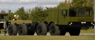
The collapse of the Soviet Union led to the end of serial production of the basic chassis of the MAZ-543 family, but their small-scale production on orders continued until the mid-2000s. By that time, a total of over 11 thousand vehicles of the 543rd series had been assembled in Minsk, which housed more than 70 main serial weapons systems and special military equipment. In 1990, to replace the already outdated MAZ-543 vehicles, the first prototype of the fourth generation was created - a multi-purpose four-axle 22-ton MAZ-7930 vehicle with a multi-fuel 500-horsepower V12 engine and a multi-stage transmission from the Yaroslavl Motor Plant, a fundamentally new welded monoblock cabin and mock-up high-sided body. Prototypes were tested until 1994, entered production in 1998, and in February 2003 were accepted for supply to the Russian Army under the MZKT-7930 brand. Despite this, to this day all MAZ-543 series vehicles remain in the MZKT production program and, if necessary, can be put back on the assembly line.
A prototype of a promising 22-ton tactical chassis vehicle MAZ-7930. 1990
Application options
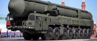
On the basis of various modifications of the MZKT-7930, a wide variety of weapons systems of the Russian army are deployed:
- operational-tactical missile systems "Iskander";
- coastal missile systems "Bal", "Bastion", "Club-M";
- coastal self-propelled artillery units A-222 "Bereg";
- multiple launch rocket systems "Uragan", "Polonaise" (Belarusian);
- coastal surface and air reconnaissance complexes "Monolit-B";
- antenna posts of the S-400 Triumph anti-aircraft missile system and the first prototype of the S-500 Prometheus anti-aircraft missile system;
- support vehicles for strategic missile systems "Topol-M" (combat duty, engineering support and camouflage, heavy mechanized bridge and others).
Modifications
The MZKT 7930 series includes several modifications:
- MZKT 7930 – basic chassis with a load capacity of 22.2 tons, a YaMZ 846 engine and a GMP MZKT-5561 mechanical transmission;
- MZKT 7930-300 – chassis with a load capacity of 24.2 tons, a YaMZ 846 unit and an automatic transmission GMP MZKT-5561;
- MZKT 79306 – export chassis with a load capacity of 24 tons, foreign Deutz BF8M1015C engine and Allison HD45P automatic transmission;
- MZKT 7415 - a truck tractor with a load capacity of 17.8 tons, a YaMZ 846 engine and a YaMZ 202-04 manual transmission;
- MZKT 7930-313 is the latest experimental model based on the MZKT 7930, used as the basis for the V-300TZM and V-300BM vehicles (Polonez-M MLRS).
Special machines have been developed based on the MZKT 7930:
- armed systems: BRK "Bastion", OTRK "Iskander", BSAU A-22 "Bereg", MLRS "Polonaise", MLRS "Uragan-1M", BMK "Bal" and others;
- antenna post of the S-400 "Triumph" air defense system;
- 15M69 camouflage and engineering support vehicle;
- coastal reconnaissance complex "Monolit-B";
- RCSN Topol-M support vehicle.
Design and device features
The MZKT-7930 heavy truck is equipped with a rigid spar-type frame (with a channel section of the side members). The vehicle is equipped with front and rear towing mechanisms, in some versions - two towing forks in the front and a towing device at the rear.
Both the front and rear suspensions of the car are independent, torsion bar type (reinforced or standard hydraulic shock absorbers are used). The MZKT-7930 vehicle is capable of moving off smoothly and provides a ride without shaking in the cabin, even when driving off-road. Wide-profile tubeless tires with a central inflation system play an important role in this, and not just the suspension.
Tires used size 1500×600-635, 20.5R25, tubeless, with a central tire inflation system.
The first and second axes of the MZKT-7930 are controlled. The design of the truck also uses central gearboxes with inter-wheel and center differentials, and planetary wheel gearboxes. At the same time, differential locking is not provided for steered wheels, but it is present on unsteered wheels.
Central non-through gearbox (1st and 4th axles) - a pair of bevel spiral gears (main gear) with a cross-axle differential. Central pass-through gearbox (2nd and 3rd axles) – a pair of bevel spiral gears (main gear) with an inter-axle differential, a pair of spur gears (additional gear) with an inter-axle differential. The differentials of the gearboxes of the steered wheels do not have locking, while the differentials of the non-steered wheels have locking ones. Center differentials (2nd and 3rd axles) – with forced locking with electro-pneumatic drive, controlled from the driver’s seat.
The rated voltage of the vehicle's on-board electrical network is 24 Volts. Batteries: 4 x 380 Ah.
Catalog of spare parts for MZKT-7930-200 (MZKT-7930-200):
Our catalog contains all the spare parts used in the MZKT-7930-200.
Select the node you need. To make it easier to find spare parts for the MZKT-7930-200, you can use the quick filter. Quick Filter by nodes:
- Body
BodyCabin installation
- Cabin 7930-5000200
- Installation of side windows
- Side window right, side window left
- Installation of wind windows
- Door installation
- Installation of seat pneumatic supply
- Installation of ESD system equipment
- Installation of cabin heater piping
- Installation of mirrors
- Installation of wings
- Engine
Engine
Engine Installation
- The engine is installed on the chassis
- Attaching air cylinders
- High pressure ducts
- Lubrication system and air ducts
- Air intake control units
- Air reducer
- Air system unit panel
- safety valve
- Start valve
- Grease dispenser tank 7930-1026200
- Grease dispenser
- Piston
- Installation of heater and exhaust pipes
- The heater is installed on the chassis
- Installation of engine heating system pipelines
- Installation of fuel heater power units
- Fuel filter
- Heater shut-off valve
- Installation of engine lubrication system units
- Filler plug
- Left fuel tank fuel lines
- Installation of exhaust system
- Radiator installation
- Clutch
Flywheel and clutch installation
- Gearbox Installation
- Transfer case installation
- Installation of power pipelines
- Installation of cardan shafts
- Wheel drive
- Frame
Frame 7930-2800001-30, 7930-2800001-40, 7930-2800001-50
- Wheel suspension
- Front hub installation
- Steering
Pipes and hoses for tank, valve block and pumps
- Installing a moisture-oil separator
- Electrical equipment
Installing electrical equipment in the cab
- Power take-off
Installation of power take-off 7929-4200010-10
- Tools and accessories
Installing a tow rope
Spare parts diagrams and components are presented on the website for reference purposes! We do not sell all spare parts for MZKT-7930-200 presented in this list, but many of them.
Heavy truck engine MZKT-7930
Cars of the MZKT-7930 family are equipped with YaMZ-846 turbocharged diesel power units produced by the Yaroslavl Motor Plant. This is a V-shaped, eight-cylinder, 32-valve, four-stroke liquid-cooled diesel engine with a power of 370 kW (503 hp) at 2100 rpm. The maximum torque of this engine is 1960 N.m (200 kgf.m).
The working volume of the YaMZ-846 engine is 18 liters. The cylinder diameter of this engine is 140 mm, the piston stroke is 140 mm. Compression ratio - 17.5. The operating order of the cylinders is: 1-5-4-2-6-3-7-8. Valvetrain: OHV.
The power supply system is a mechanical high-pressure fuel pump, one pump section per cylinder, with direct injection. It is located in the camber of the cylinder block, between the rows of cylinders. The injection pump is eight-plunger, driven by a centrifugal clutch, with automatic regulation of diesel fuel injection advance. All plungers are arranged in a row.
The intake pipes are located in the camber of the cylinder block. The valves (4 for each cylinder) are located in the cylinder head and are driven through rocker arms and rods from the lower camshaft. It is located in the cylinder block and is driven through 2 gears, which are located at the front end of the engine and are covered with a cover.
The rods are equipped with roller pushers. The crankpins of the crankshaft are placed at an angle of 90 degrees, for uniform flashes every 90°. The connecting rods are made offset. Cylinder liners are cast from high-strength cast iron. All intake and exhaust valves are equipped with two springs. A special lock connects the spring plates to the valves, ensuring their rotation during engine operation.
The engine camshaft is steel, stamped, with movement from cams, separate for each valve, and transmitted by rods with roller tappets. The crankshaft is made by hot stamping from steel. The first and fourth cranks are placed at an angle of 180 degrees in a plane perpendicular to the plane of the second and third cranks, which are also shifted relative to each other by 180 degrees. The engine pistons are cast from high-silicon aluminum alloy, and each of them has two compression rings and one oil scraper ring.
The Deutz BF8M1015C diesel engine, which was equipped with the experimental export version of the MZKT-7930, had a similar design and similar power. This is also a V-shaped, eight-cylinder turbocharged diesel engine. Its working volume is 15.87 liters; rated power - 400 kW (544 hp); maximum torque – 2350 N.m. Cylinder diameter – 132 mm, piston stroke – 145 mm. Compression ratio: 16.5.
The entire power unit is protected by a metal casing. In addition to it, hydraulic system containers, a battery pack, and two radiators, one of which is combined with a charge air cooler, are also hidden under the casing. The sides of the casing are removable to ensure maintenance of systems and units.
Engine
The base for the MZKT 7930 is the Russian diesel engine YaMZ 846. The V-shaped “eight” was created specifically for this equipment. The unit is equipped with direct fuel injection, turbocharging and charge air cooling.
Characteristics of the YaMZ 846 engine:
- working volume – 17.24 l;
- rated power – 370 (503) kW (hp);
- maximum torque – 1960 Nm;
- cylinder diameter – 140 mm;
- specific fuel consumption – 203 (149) g/kW per hour (g/hp per hour).
For the MZKT 79306 version, a foreign diesel engine, Deutz BF8M1015C, is offered. The 8-cylinder unit has 2 turbochargers, direct fuel injection and a liquid cooling system. Design features include compact dimensions, a cast-iron crankcase and cast-iron cylinder heads. The motor is characterized by increased resistance to loads.
Deutz BF8M1015C engine characteristics:
- working volume – 15.87 l;
- rated power – 400 (544) kW (hp);
- maximum torque – 2350 Nm;
- cylinder diameter – 132 mm;
- compression ratio – 16.5.
Transmission options for MZKT-7930
Depending on the modification of the truck, it can be equipped with various versions of transmissions:
- mechanical GMP MZKT-5561 (6 forward speeds, 1 reverse) - for MZKT-7930;
- mechanical YaMZ 202-04 (9 – forward, 1 – backward) – for the MZKT 7415 truck tractor;
- automatic GMP MZKT-5561 (6 – forward, 1 – backward) – for MZKT 7930-300;
- automatic Allison HD45P (6 - forward, 1 - reverse), with a single-stage locking torque converter with a single-disc friction clutch with a hydraulic drive - MZKT 79306.
Regardless of the modification, the MZKT-7930 is equipped with a two-speed transfer case with a lockable inter-vehicle differential.
Drive axles (for all models) – central gearboxes with interaxle and cross-axle differentials, planetary wheel gearboxes.
Brake and steering system
The brake system of the MZKT-7930 vehicle includes several subsystems. The main one uses a double-circuit mechanism with a pneumohydraulic drive. The parking brake subsystem has a spring energy accumulator for braking. A mechanical device is also used for emergency release of the parking subsystem.
The spare brake subsystem consists of a working circuit of the working subsystem and is activated in case of problems in one of the circuits. The auxiliary subsystem uses an electro-pneumatically controlled engine brake.
Steering system: left/right steering wheel, equipped with hydraulic booster.
Cabin MZKT-7930
The cabin of this car is rigid, fiberglass, two-door, three-seater, with an adjustable steering wheel, an informative instrument panel with adjustable backlight brightness. The MZKT-7930 cabin is pushed forward, in front of the engine and chassis. This arrangement helps to mount superstructures of serious size without going beyond the dimensions. Excellent visibility into the cabin of a heavy truck is ensured by tilting the three-section windshield at a slight forward angle.
The car starts moving smoothly, like a car. The gas pedal is soft, responsive to any driver action due to its smooth movement. The engine runs smoothly and is practically inaudible in the cabin.
The cabin is equipped with a powerful heater (and as an additional option - air conditioning and an even more powerful heater, or an autonomous heater. Other additional options include an armored cab, a powerful fan, a winch, tires with the Ranflat system (holding the tire on the rim even after a complete loss of pressure from puncture).
Also, the MZKT-7930 cabin is standardly equipped with thermoses for drinking water, a first aid kit, two OU-3 manual fire extinguishers, and it has space for installing brackets for weapons.
The cabin is quite comfortable, but without frills
What does this mean, first of all? The conclusion is clear - the MZKT 7930 vehicle is intended for use in off-road conditions. Let's talk in detail about the cabin. The place where the driver is located is quite spacious and comfortable. The cabin has excellent visibility thanks to the tilting of the three-section windshields. Moreover, the cabin looks unusual and original if we consider the issue of design.
The driver's seat is quite soft and sits comfortably on a special air suspension. There is also the possibility of adjusting the seat. This is an important element that helps the driver have a fixed position while driving in order to safely operate the car.
The instrument cluster and panel are made in a modern style. If we talk about the steering wheel, it has become quite comfortable both in terms of the thickness of the rim and the diameter. Since the gearbox is automatic, the pedal unit also has two pedals: gas and brake. The gearbox drive joystick itself is conveniently located on the console; it is very easy to reach and is located on the right side of the driver. To the left of the driver's seat is the parking brake lever.
If we talk in detail about the cabin itself, it is made of durable plastic. The developers immediately designed a car for army needs, but later realized that civilian comfort would clearly be in place here, so when decorating the inside of the cabin, they used not pressed cardboard as is usually done for army vehicles, but durable molded plastic. All seats are covered with durable fabric and equipped with special seat belts.
To keep the cabin warm in winter, a special device is provided - a liquid-air heater. The cabin has an air conditioner (Convecta KL-3AT/4), which makes it possible to provide ventilation and create comfort.
In the cabin of MZKT 79306 you can see thermoses with drinking water, a pair of fire extinguishers and a first aid kit. It is possible to install weapons on special brackets. In order to enter the cabin, there are steps that are conveniently located under the door. One of them is the lower folding type, and the upper one is solid and stretches along the entire cabin. The doors open as wide as possible.
Main technical characteristics of MZKT-7930 in numbers
- Overall dimensions: length 12669 mm, width – 3070 mm, height – 3017 mm.
- Weight parameters: gross vehicle weight - from 38,800 to 45,200 kilograms, curb weight of the vehicle - from 20,500 to 21,000 kilograms (depending on modification).
- The machine's carrying capacity is from 17,800 to 25,000 kilograms (depending on modification).
- Permissible axle load: 2×10350, 2×9150, 2×11050, 2×10950 (first and second); 2×11325, 2×10250, 2×11550, 2×11550 (third and fourth).
- Wheel formula – 8×8.
- Maximum speed – 70 km/h.
- The maximum climbable grade is 55 percent.
- The approach angle is 25 degrees.
- The departure angle is 35 degrees.
- Ground clearance - 400 millimeters.
- Vertical obstacle – 350 millimeters.
- Side slope - 40 percent.
- The turning radius (along the track) is 15 meters.
- The depth of the ford is 1.4 meters.
- The width of the ditch to be overcome is 2 meters.
- Power reserve – 1000 kilometers.
- Operating temperature – from –50 to +50°C.
- Fuel tank capacity – 2×385 liters.
- Air transportability - An-22, An-124.
Auto reporters from the magazine “Fixed Means”, who had a chance to take a test drive of the civilian modification of the car - MZKT-79306 - were surprised at how easy and convenient the car was to control - the steering wheel can be turned with just one finger.
Maneuverability is also enviable. From a deep skid, a huge truck gets onto the course confidently and easily, even when driving over rough terrain. Such controllability and maneuverability of a 4-axle vehicle is explained by the fact that it is equipped with an excellent steering mechanism with a powerful hydraulic booster (four wheels are still controlled and also driven), the failure of which is duplicated by a spare system.
The cost of these machines is not disclosed and is determined individually. By the way, it’s the same story with most BelAZ vehicles.