How are units classified?
Excavators equipped with a working body with one bucket are divided into categories:
- By functional purpose. There are machines designed for construction work, special and quarry ones. The latter are equipped with a reinforced bucket designed for working with rocks.
- The design of the chassis is wheeled on a special chassis, wheeled on a car chassis, or tracked. The latter can be equipped with caterpillar tracks with increased width.
- By type of drive of the working body - hydraulic, electric, combined.
What to do if the undercarriage of specialized tracked equipment is faulty
Downtime of equipment due to a malfunction of the chassis, no matter whether it is tracked or wheeled, is not acceptable for the owner. This directly affects the level of his income, so it is extremely important to quickly organize repair and restoration work. What does that require:
- Find good specialists who understand such systems and are ready to quickly and with a guarantee restore the functionality of the chassis of special equipment.
- Provide craftsmen with quality spare parts.
The second problem is very easy to solve if you contact the Trade-Service company, which provides its clients with the following advantages:
- Availability of the maximum possible range of spare parts to restore the performance of the tracked undercarriage of any modern special equipment.
- High-quality, original products.
- Reasonable cost of spare parts that is favorable for our customers.
- Prompt delivery and qualified assistance from our own specialists.
Do you want your special equipment to return to its ability to solve assigned tasks as quickly as possible? Do you want to receive guarantees of reliability and durability? Carrying out all the planned work is not too expensive for your budget? Then contact the specialized company Trade-Service!
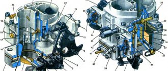
How does an excavator work?
The general design of an earth-moving excavator includes:
- chassis;
- engine;
- hydraulic system;
- transmission;
- cabin with controls;
- platform with a rotating device;
- working boom.
An internal combustion engine with compression ignition is mounted on the turntable. The motor has a liquid cooling system. The cooling fans are driven automatically, but there is a forced switch. To increase power and reduce fuel consumption, turbochargers are installed. The engine drives the working mechanisms of the excavator through a hydraulic or electric transmission. Mechanical transmissions are used on outdated equipment.
The rotating part is mounted on the chassis through a shoulder strap, providing 360° rotation. The platform houses the operator's cabin, hydraulic and electrical systems, and a boom with drive and control mechanisms. The excavator boom can be equipped with a variety of bucket designs or a trencher, which reduces the time required to create trenches. It is possible to install hydraulic hammers or other equipment necessary for excavation work.
Mechanically driven excavators use winches that directly control the movement of the boom. On machines there are winches with 1 or 2 shafts. A single-shaft unit is considered to be one in which the lifting and traction drums are installed on a single shaft. If the winch drums are spaced along the shafts, then it is called a 2-shaft winch. Similar mechanisms are installed on large excavators.
The winches are driven by shafts through a gearbox or by a chain from the main transmission shaft. Multi-disc friction clutches are used for starting, and band brakes are used for stopping. The cable is laid on the drum in one or several layers depending on the length.
The design of a mini-excavator does not differ from the principles inherent in full-size equipment. The difference lies in the simplification of the hydraulic design and the use of a small-sized diesel engine. The operator's workplace is located in a closed cabin equipped with ventilation and heating systems.
The design of the backhoe loader differs from the mechanism described above. The work bucket is located on an articulated boom at the front of a standard wheeled tractor. The loading equipment has a hydraulic drive, which is controlled from the operator's cabin.
The tractor is built according to the classical design - the engine and gearbox are part of the supporting structure. There is a subframe installed at the front that serves to support the engine and front axle. An excavator boom or other earth-moving equipment equipped with a hydraulic drive is installed on the rear of the machine. The boom can be rotated at a fixed angle. When digging pits and trenches, equipment moves under its own power.
Slewing ring
Excavators mounted on tractor chassis are rotated using hydraulic cylinders. Full-rotary equipment has a hydraulic or electric drive that rotates the platform with working equipment around a stationary chassis.
The excavator's slewing bearing ensures rotation of the platform around a vertical axis. Increased demands are placed on the strength of the unit, since it ensures that the platform is held on the chassis while the excavator is operating. The design of the rotating device uses rotating bodies in the form of rollers or balls.
Rollers are used on older models of excavators. The disadvantage of the design is the gap between the rotating body and the working surface of the shoulder strap, which leads to the platform rocking during the rotation process. Ball devices do not have this drawback. In addition, the ball swivel ring has less weight and reduced rotational resistance. The rotating bodies are installed in a ball structure in 1 or 2 rows.
The rotating mechanism consists of 2 rings, which are fixed together with bolted connections. The mechanism is rigidly attached to the turntable. The balls located inside are separated by a separator, which prevents the unit from jamming during operation.
A gear ring is installed on the rotating part, designed to rotate the platform. An axial piston engine equipped with a geared operating shaft is used for turning. It is possible to use mechanical gearboxes that increase torque. The rotation speed is adjusted by changing the oil pressure supplied to the hydraulic motor. The platform is kept from accidental rotation by mechanical and hydraulic brakes.
Crawler excavators turn around using tracks and brake mechanisms. Depending on the turning radius, one track is braked with different amounts of force.
Hydraulic system
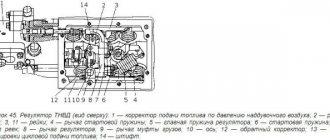
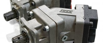
The excavator's hydraulic system operates from axial piston or gear pumps mounted on the machine engine. The pumps are driven through a step-up gearbox. The engine may have a small pump used to operate the hydraulic power steering. The pump is driven by timing gears.
The supply of working fluid is located in a supply tank equipped with a system for purifying the oil from impurities. A special oil is used as a working fluid, adapted for operation in axial piston units and which does not destroy the rubber elements of the lines. There are summer and all-season oils, which differ in their pour point.
The liquid is supplied from the tank to the pump and then goes to the hydraulic distributor. Flexible hoses and metal pipelines are used to connect the hydraulic circuit components. The couplings installed on them connect the nodes into a common line, ensuring the tightness of the structure. The distributor is equipped with spool valves that supply fluid to hydraulic equipment. The used oil enters the radiator and then, after passing through the filters, returns to the tank.
The hydraulics are equipped with safety valves that protect the system from overpressure. Bypass valves are used that divert part of the liquid into containers with reduced pressure. Flow adjustment is carried out by throttles and spools, which block the cross-section of the lines. Some mechanisms use a hydraulic lock to prevent backflow of fluid. Such valves are used on outriggers.
Double-acting hydraulic cylinders are used to operate the boom. Cylinders are used to rotate the boom, change the angle of the handle, and control the movement of the bucket. There is an eye on the cylinder rods that connects to the controlled units.
Hydraulics are used as an excavator transmission. Axial piston motors are installed on the drive wheels or sprockets. The speed of the machine depends on the operating pressure in the hydraulic system. The pressure is regulated by the engine speed, as well as by the hydraulic distributor. The steering is equipped with a power amplifier connected to a common or separate line. The brake mechanisms on the wheels and working parts operate using hydraulics.
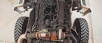
Chassis
The chassis is designed to move equipment and transfer loads from components and working equipment to supporting surfaces.
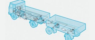
There are 2 chassis options:
- wheeled on pneumatic tires;
- tracked
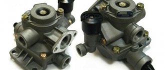
The wheeled chassis consists of 2 axles equipped with a drive. The front axle is equipped with movable knuckles that allow the excavator to rotate while moving. The steering axle design uses stabilizers to ensure lateral stability of the machine. The advantage of pneumatically driven machines is their high speed, which allows the excavator to be moved between construction sites without additional transport.
On wheeled vehicles there are brakes equipped with a pneumatic drive. A compressor mounted on the engine is used as a source of compressed air. The differential locking mechanisms and the front axle connection are powered by pneumatics. When towing an excavator, the pneumatic system is connected to the outlet of the tractor's brake system.
The wheels are driven by individual hydraulic motors or from a single engine and transfer case. The box is connected to the bridges by cardan shafts. There is no wheel suspension. Axle drives use differentials with the possibility of forced locking. Planetary gearboxes are installed in the wheel hubs to increase torque.
Tracked vehicles are equipped with mechanisms for changing the track, which increases the stability of the machine. To work in swampy areas, extended tracks are used, which are installed on standard rollers and drive wheels. Crawler excavators have low moving speeds, so they are transported on special trailers.
On outdated excavators, a chain drive is used to drive the drive sprockets, which is not reliable. Electrical installations can be used as engines for such equipment. The source of electricity is a traction generator or an external device. Individual hydraulic motors provide increased maneuverability and reliable operation.
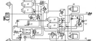
Electrical diagram
The electrical circuit of an excavator uses the machine body as a negative conductor. The operating voltage of the electrical equipment in the circuit is 12 or 24 V. The current sources are the generator installed on the engine and the battery.
The main purpose of the electrical system is to start the engine and illuminate the workspace around the machine at night.
Electric drives have a driver's cab ventilation system, instrumentation and external light signaling. Autonomous heaters are installed on excavators operating in low temperature conditions. The devices warm up the engine and cabin to a comfortable temperature.
Track Tension
As can be seen from previous chapters, track chain tension significantly affects the wear rate of most parts of the running mechanism, as contact stresses increase.
However, loose track chain tension is one of the main causes of improper contact of parts and, consequently, harmful effects on the side surfaces of the chain links and the side surfaces of the flanges of rollers and wheels. Therefore, the performance and durability of the chassis parts depend on the correct tension of the track chain.
How to measure track tension. Track slack between carrier rollers is a parameter commonly used to measure chain tension.
The chain tension is determined in the following order:
- slowly move the machine forward on a flat horizontal surface;
- stop the machine in a position where the lug is located directly above the support roller;
- make sure that the lugs are worn evenly (have the same height) and place a measuring stick on the two lugs between the support roller and the idler wheel (see figure);
- measure the distance f between the ruler and the top of the lug at the place where the sag is greatest.
Recommended track slack amount. Unless a different value is specified in the instructions for the machine, it is recommended to rely on the following values: tractors – f = from L/25 to L/35; excavators – f = from L/35 to L/50.
Excavator operating principle
Equipment equipped with one bucket performs work cyclically, which is why the activity is carried out intermittently. This ensures the versatility of the machine; the excavator can be used for loading and unloading operations. The boom cylinder installed on excavators can operate hydraulically and can also be switched to a floating mode, allowing the bucket to be loaded with the weight of the equipment. Activation of the floating mode is carried out by the driver as necessary by pressing the pedal.
The excavator operation diagram is as follows:
- at the first stage of the working stroke, soil is taken from the trench into the bucket;
- after this, the platform rotates around a vertical axis, transferring the soil to the dump site;
- then the reverse stroke is performed and the cycle begins again.
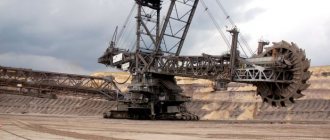
The operating principle of a continuous excavator is based on the movement of several buckets, which automatically throw the soil to the side, forming a dump. The working elements are installed on the rotor or chain. Chain excavators use a mounted or semi-mounted working tool. The chain sprocket is driven mechanically or hydraulically. Digging depth and force are created using a hydraulic mechanism. The excavated soil is fed onto a conveyor belt, which takes it to the side.
Additionally, the excavator is equipped with a bulldozer blade controlled by a hydraulic cylinder. The knife is used to level the working area.
New threads are not cut into the bolt mounts
And again replacing the fasteners. Already on any section of the chassis. If there were any creases, the remaining rods were drilled out correctly. If the bolts remain intact, they have been removed and new ones must be installed.
Right
- Before installing new fasteners, go through the holes with taps. This will remove rust, correct kinks in the threads, and prevent the bolts from breaking.
- Use a torque wrench (the owner's manual will usually tell you how much to tighten the fasteners).
Wrong
No taps, everything is done quickly, using the tools that are at hand. Screw the bolt into the old, rusted and partially torn thread during dismantling. Instead of a torque wrench, they use brute force and improvised objects - sometimes three people tighten one bolt.
Why is it wrong
A bolt with rust or broken threads is tight, it is pulled with too much force, it is overtightened. The result is that the bolt is broken, see point 1 about drilling. If you don’t have a large torque wrench, and the operating instructions with tension values were seen the last time you received new equipment, there is again a big risk of overtightening and breaking the bolt.