The parking brake (also known as the handbrake, or in common parlance “handbrake”) is an integral part of the car’s braking control. Unlike the main braking system used by the driver while driving, the parking brake system serves primarily to hold the vehicle in place when parked on sloped surfaces, and can also be used as an emergency emergency braking system in the event of failure of the main one. From the article we will learn about the design and principle of operation of the handbrake.
Design and principle of operation of the parking brake
The parking brake (also known as the handbrake, or in common parlance “handbrake”) is an integral part of the car’s braking control. Unlike the main braking system used by the driver while driving, the parking brake system serves primarily to hold the vehicle in place when parked on sloped surfaces, and can also be used as an emergency emergency braking system in the event of failure of the main one. From the article we will learn about the design and principle of operation of the handbrake.
What is a brake valve?
The brake valve is an integral component of the brake system of special equipment and vehicles equipped with a pneumatic drive. Its task is to supply compressed air mass to the actuators and other elements of the system when the braking process is activated. The list of part functions includes:
- maintaining the integrity of the system regardless of unfavorable environmental factors;
- “brake pedal feel”, that is, the feeling of effort on the pedal depending on the degree of braking;
- maintaining the operability of equipment in the event of an air leak in one of the chambers (for two-section types).
Thanks to the brake valve, the brake system is controlled during operation of the machine. The importance of the element can hardly be overestimated, since its malfunction leads to the failure of the entire braking system.
The principle of operation of the braking system
Functions and purpose of the hand brake
The main purpose of the parking brake (or handbrake) is to hold the car in place during long periods of parking. It is also used in case of failure of the main brake system during emergency or emergency braking. In the latter case, the handbrake is used as a braking device.
The handbrake is also used when making sharp turns on sports cars.
The parking brake consists of a brake drive (usually mechanical) and brake mechanisms.
Joomla Website
| Article Index |
| Brake control |
| Service brake system |
| Brake control faults |
| Brake systems KamAZ-5350 |
| Operation of the pressure regulator |
| Service brake system |
| Brake valve operation |
| Parking brake system |
| Auxiliary braking system |
| Maintenance of brake systems and possible malfunctions |
| Possible malfunctions of the brake systems of KamAZ vehicles |
| Brake control of the car Ural-4320-31 |
| Parking brake system. |
| Auxiliary braking system |
Page 8 of 14
Parking brake system
The parking brake system is designed to hold the car stationary in a parking lot; it can serve as a backup brake system, braking the car if the service brake system fails. The parking brake system brakes the vehicle using the brake mechanisms of the rear axle (rear bogie), which are driven by spring energy accumulators located above the brake chambers of the service brake system. Moreover, energy accumulators have reverse action - when air is supplied to its working cavity, the brake mechanism is released, and when air is released, it is braked due to the energy of a compressed spring. This provides increased safety when operating the vehicle.
The drive of the parking brake system (circuit III) is pneumatic.
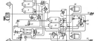
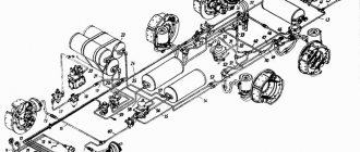
1 – four-circuit safety valve; 2 – accelerator valve; 3 – switch for the parking brake system warning lamp; 4 – control valve; 5 – break valve;
6 – control valve for trailer brake systems with a two-wire drive; 7 – switch for emergency air pressure drop alarm; 8 – receiver; 9, 15 – control valve; 10, 12 – automatic connecting head; 11 – connection head type A; 13 – control valve for trailer brake systems with a single-line drive; 14 – spring energy accumulator; 16 – two-line bypass valve;
17 – emergency brake release valve
Figure 12.30 — Drive of the parking brake system and trailer brake systems
The drive consists (Figure 12.30) of a four-circuit safety valve section 1, a receiver 8, a manual control valve 4, a two-line bypass valve 16, an accelerator valve 2, an emergency brake release valve 17, spring energy accumulators 14, a parking brake system warning lamp switch 3, an emergency warning lamp switch drop in air pressure in circuit 7, control valves 9 and 15.
The source of pressure in the circuit is a receiver with a capacity of 20 liters. The receiver 8 contains a switch for signaling an emergency drop in air pressure in the circuit, a condensate drain valve, and a control valve 9.
{loadposition adsense_720_90}
The actuators of the parking brake system are spring energy accumulators mounted on the covers of the brake chambers of the rear brake mechanisms.
The spring energy accumulator (Figure 12.25) consists of a housing 1, a piston 5 with a power spring 8, a pusher 4 with a thrust bearing 2, a screw of the emergency brake release mechanism 9.
When the brake is released, compressed air is supplied to the cavity under the piston from the accelerator valve of circuit III. Under the influence of air pressure, piston 5 rises upward, compressing power spring 8. Pusher 4 also rises upward along with piston 5, releasing the brake chamber membrane of the working brake system. The brake mechanism is released.
When braking with the parking brake system, air from the under-piston space is released into the atmosphere through the accelerator valve.
The power spring moves the piston 5 down. In this case, the pusher 4, with its thrust bearing 2, acts on the brake chamber membrane and moves it along with the rod down. The brake mechanism is slowed down.
If there is no compressed air in the pneumatic system, the car is braked by spring energy accumulators. If there is a sudden loss of compressed air pressure in the pneumatic system, for example, if the pipeline in circuit III is damaged, the vehicle automatically brakes, which increases traffic safety.
To tow a faulty vehicle, it is possible to emergency release the spring energy accumulators using screw 9. To do this, it is necessary to unscrew the screws from the housing to the maximum amount (approximately 120 mm). In this case, the screw, through the thrust bearing 13, acts on the pusher and piston, moving them upward. The power spring is compressed, releasing the brake chamber diaphragm and rod.
It is strictly prohibited to disassemble spring energy accumulators without special tools!
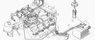
Compressed air is supplied to the spring energy accumulators from receiver 8 (Figure 12.30) through accelerator valve 2 installed on the right frame side member in the area of the rear (intermediate) axle. The relay valve is controlled by a manually operated reverse acting brake valve located in the cab to the right of the driver's seat. The term “reverse action” means that in the initial state, during movement, it supplies compressed air to the spring energy accumulators, and when braking, releases air from them into the atmosphere.
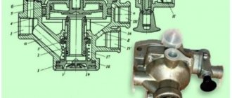
The parking brake system control brake valve (Figure 12.31) is designed to control the spring energy accumulators of the parking brake system drive. It consists of a body 1, a body cover 8 with a handle 19 and a lock 21, a piston 3 with an outlet valve 13, a rod 12 with a guide 10, a figured ring 9, a guide cap 20, a balancing spring 4, a piston 16 with a spring 17 and an adjusting screw 18 .
Compressed air from the receiver is supplied to the manual brake valve through terminal IV. Terminal II is connected to the control cavity of the accelerator valve. Through terminal III, the brake valve is connected to the atmosphere. Terminal I is connected to the middle cavity of the trailer brake control valve with a two-wire drive. Cavity A is connected by a channel to terminal I.
The follower piston 3 has an inlet seat, to which the valve 13 is pressed using a spring, performing, in this case, the function of an inlet valve, and when interacting with the seat made at the end of the rod 12, the function of an outlet valve.
1 – body; 2, 22, 23 – spring; 3 – follower piston; 4 – balancing spring;
5 – spring plate; 6 – axis with roller; 7 – tap handle; 8 – cover; 9 – figured ring; 10 – rod guide; 11 – sealing ring; 12 – rod; 13 – valve; 14 – retaining ring; 15 – valve with spring; 16 – piston; 17 – piston spring; 18 – adjusting screw; 19 – handle; 20 – guide cap; 21 – clamp; I – output to the trailer brake systems control valve with a two-wire drive; II – output to the accelerator valve; III – atmospheric output; IV – supply input; A – cavity
Figure 12.31 — Brake valve for controlling the parking brake system
The brake valve handle can occupy two fixed positions (Figure 12.32). In position I, compressed air enters the energy accumulators, which ensures a disinhibited state.
1 – locking strip; 2 – locking roller; I – disinhibited state; II – braking with the parking brake system; III – trailer release
Figure 12.32 — Positions of the brake valve handle
In position II, compressed air from the energy accumulators is released into the atmosphere - the car is braked by the parking brake system. When the lever is moved to the non-fixed position III (until the roller 2 stops in the groove of the locking plate 1), air is supplied to the middle cavity of the trailer brake system control valve with a two-wire drive, which leads to the release of the trailer while the driver holds the handle in position III. This position is used to check the reliability of holding the road train on a slope by the parking brake system of the tractor vehicle. This simulates the possible release of the trailer's brakes during long-term parking due to leakage of compressed air from the trailer's brake drive. After checking, the handle automatically returns to position II. If the handle is fixed between positions I and II, the air pressure in the energy accumulators is also fixed at a value proportional to the angle of rotation of the brake valve handle. This feature of the brake valve allows the parking brake system to be used as a backup.
In the braked state (with the valve handle in a horizontal position), compressed air passes through the open inlet valve of the valve into output II and then into the control cavity of the accelerator valve and the middle input of the trailer brake control valve with a two-wire drive. Compressed air is supplied through the accelerator valve to the cavities of the energy accumulators. The power springs are compressed and the vehicle's brakes are released. At the same time, the trailer brake control valve releases the trailer brakes.
When you turn the tap handle together with the cover 1 (Figure 12.33.), the guide cap 2 rotates. Sliding along the screw surfaces of the ring 3, the cap 2 rises up and carries the rod 12 along with it (Figure 12.31). The outlet seat comes off the valve 13, and the valve, under the action of the spring 2, rises until it stops against the seat of the follower piston 3.
1 – cover; 2 – guide cap; 3 – figured ring
Figure 12.33 — Guide cap
As a result, the passage of compressed air through input IV to output II stops; through the open outlet in valve 13, compressed air is released into the atmosphere through port III until the force of air pressure in cavity A under piston 3 overcomes the forces of the balancing spring 4 and the air pressure above the piston in cavity B. Overcoming the force of spring 4, the piston 3, together with valve 13, rises up until valve 13 comes into contact with the outlet seat of rod 12, after which air release stops.
With further rotation of handle 19, a similar process occurs, which leads to a greater drop in air pressure in terminal II.
This is how the brake valve follows the action, ensuring a linear dependence of the pressure in terminals II and I on the angle of rotation of the brake valve handle
The operating diagram of the STS brake valve is shown in Figure 12.34.
a b
a – disinhibited state; b – braking
Figure 12.34 — Scheme of operation of the brake valve of the parking brake system
The stop bar of the faucet has a profile that ensures that the handle automatically returns to the lower position when it is released. Only in the uppermost position does the lock 21 (Figure 12.34) of the handle 19 fit into a special cutout of the locking bar and fixes the handle.
In this case, the energy accumulators communicate with the atmosphere through an accelerator valve, and braking efficiency is maximum.
To release the spring energy accumulators, the valve handle 19 must be pulled up, while the latch comes out of the groove of the locking plate, and the handle 19 freely returns to the lower position. When stopping with a trailer on a slope, the driver must make sure that a possible air leak from the brake system of the trailer will not lead to unauthorized movement of the road train due to the release of the trailer. To do this, after stopping on a slope, you need to move the brake valve handle to position III (Figure 12.32) and hold it in this position for several seconds. In this case, compressed air is supplied to output I and then to the middle input of the trailer brake control valve with a two-wire drive. The trailer is released. After releasing the brake valve handle, due to the inclined surface in the groove of the locking plate, it returns to position II. The trailer brakes again.
Compressed air can be supplied to the parking brake system drive in two ways. The first way involves supplying compressed air through the four-circuit safety valve section. Setting the safety valve section ensures that the parking brake system circuit reservoir is filled last, after the service brake system reservoirs are filled. This ensures that all braking systems are ready to operate before the vehicle starts moving, which takes a few minutes.
In order to reduce the time required to prepare the vehicle for movement in emergency cases, an emergency brake release valve 17 is installed in the brake drive (Figure 12.35), which allows, if necessary, to supply compressed air to the accelerator valve and the parking brake system control valve directly from the supply circuit, bypassing four-circuit valve. Since in this case there is no resistance in the path of compressed air in the form of valves closed under the action of springs, compressed air, with the brake valve handle in a horizontal position, freely passes into the cavity of the energy accumulators, bypassing the receiver. The car is released 10-20 seconds after starting the engine.
To reduce the likelihood of an emergency, the emergency brake release valve must be constantly in the closed position and open only when necessary.
The emergency brake release valve (Figure 12.35) is located on the first cross member of the frame on the right side in the area of the headlight and in appearance resembles a control outlet valve.
1 – body; 2 – spring; 3 – pusher; 4, 5 – sealing ring; 6 – tape; 7 – wing nut; 8 – washer; 9 – gasket
Figure 12.35 — Emergency brake release valve
It consists of a housing 1, in which a pusher 3 is located, with sealing rings 4 and 5. Under the action of a spring 2, the pusher 3 is pressed against the seat in the housing, separating the inlet and outlet openings. A wing nut 7 made of polymer is screwed onto the threaded section of the body. In the off position, it should be screwed onto 2-3 threads. To open the valve, the wing nut must be tightened until it stops. The pusher with O-ring 4 will move, releasing the seat for air to pass from the supply circuit to the parking brake system control valve and the accelerator valve through the two-line bypass valve.
Double-line bypass valve 16 (Figure 12.36) is designed to power pneumatic devices from one of two compressed air lines connected to the valve. It consists of a body 2 with a cover 3, between which an o-ring 4 is installed. A membrane 1 is located in the valve cavity in a free state.
1 – membrane; 2 – body; 3 – cover; 4 – sealing ring; I, II – inputs; III – conclusion
Figure 12.36 - Double-line valve
The valve is connected to the supply line from the pressure regulator on one side, and from the receiver of circuit III on the other. The third output of the valve is connected to the input of the parking brake system control valve, as well as to the input of the accelerator valve of circuit III. When air is supplied from the pressure regulator, membrane 1 moves and closes the line inlet from the receivers, the compressed air passes to the parking brake system control valve and to the accelerator valve. When using compressed air from the receiver, the membrane closes the line inlet on the side of the pressure regulator. Compressed air again passes to the parking brake system control valve and to the accelerator valve, but comes from the receiver.
Circuit III, in addition to the parking brake system, provides power to the trailer brake systems and also controls them. All-wheel drive vehicles of the Mustang family are equipped with a combined (one- and two-wire) drive of trailer brake systems: In a single-wire drive, the power supply of the receiver and the control of the trailer air distributor are carried out through one line, which has a type A connecting head. Moreover, during long-term continuous braking, the brake receiver is refilled trailer system does not occur. In a two-wire drive, the receivers are constantly powered through the supply line, and the trailer air distributor is controlled through a separate control line. Both lines have automatic connection heads.
The trailer brake control circuit includes a two-wire trailer brake control valve, a single-wire trailer brake control valve, two automatic coupling heads and one type A head.
The trailer brake system control valve with a two-wire drive (Figure 12.37) is designed to activate the trailer brake pneumatic drive when the service, spare and parking brake systems of the tractor or any of the circuits are activated separately.
1 – membrane; 2, 9, 11 – springs; 3 – unloading valve; 4 – inlet valve; 5 – upper body; 6 – large upper piston; 7 – spring plate; 8 – adjusting screw; 10 – small upper piston; 12 – middle piston; 13 – lower piston; 14 – lower body; 15 – outlet window; 16 – nut; 17 – membrane washer; 18 – middle body; I – input from the lower section of the brake valve; II – input from the parking brake system control valve; III – input from the upper section of the brake valve; IV – output to the trailer control line; V – output to the trailer supply line; VI – atmospheric output;
VII – input from the receiver
Figure 12.37 — Trailer brake control valve with two-wire drive
The valve consists of a body made of three parts. On the right side, break valve 5 is attached to the body with two bolts (Figure 12.37).
Between the lower 14 and middle 18 housings (Figure 12.37) a rubber membrane 1 is clamped, which is secured between two washers 17 on the lower piston 13 with a nut 16 sealed with a rubber ring. An outlet window 15 with an attached rubber valve is attached to the lower body with two screws, protecting the device from dust and dirt getting inside. When the screws are loosened, the outlet window 15 can be rotated and access to the adjusting screw 8 can be opened through the holes of the valve 4 and piston 13. In the upper body there is a large piston 6 with a conical spring 11, in the central hole of which there is a small piston 10 with a spring 9 and an adjusting device, made integral with the exhaust seat.
In the middle section of the body there is a middle piston with a spring, in the upper part of which there is a hole and an inlet valve seat 4. In the lower part of the piston there is a retaining ring through which the middle 12 and lower 13 pistons are connected. Valve 4 is flat, acts as an intake valve, interacting with a seat made on the middle piston, and an exhaust valve, interacting with the exhaust seat of a small piston. The hollow valve stem 4 and the axial channel in the lower piston form an outlet channel that relieves pressure from the trailer brake control line. In the initial state, valve 4 is pressed against the inlet seat of the middle piston, the outlet seat is torn off from the valve and is in its uppermost position.
The trailer brake control valve with a two-wire drive directs compressed air from its source (input VII) to consumers (output IV) with simultaneous or separate receipt of control signals from three independent brake circuits of the towing vehicle. In this case, a direct-acting pneumatic signal is supplied through inputs I and III (to increase pressure, respectively, from circuits I and II of the service brake system), and through input II, a reverse-acting signal is supplied (to decrease pressure, from circuit III of the parking brake system drive). In addition, through the cavity under the middle piston 12, compressed air constantly passes from terminal VII, located in the break valve, into the supply line of the trailer through terminal V.
In accordance with the requirements of international standards for the brake control of trailers, the brake drive must ensure automatic braking of the trailer in the event of damage to the supply or control lines. If the supply line to the drive of the trailer brake systems is damaged, its braking occurs automatically due to the technical solutions incorporated into the design of the trailer air distributor. This problem is solved due to the fact that the supply line is constantly under compressed air pressure. If the supply line is depressurized, the pressure in it drops, which is a control signal for the trailer's air distributor, through which compressed air stored in the receiver is supplied to its brake chambers. The trailer brakes.
A more difficult task involves identifying damage to the trailer control line. The pressure in it appears only when braking. In the disinhibited state there is no air pressure in it. To automatically brake the trailer in the event of damage to its control line, a break valve is installed on the trailer brake control valve with a two-wire drive (Figure 12.38), which consists of a housing 8 connected to the body of the trailer brake control valve with a two-wire drive using two bolts 3 In the housing 8 there is a floating piston 1, loaded by a spring 7 with sealing rings 2 and 4, which separate the three valve cavities (A, B, C) among themselves. These cavities are connected by channels to the cavities of the control valve for trailer brake systems with a two-wire drive. The air channels at the connector are sealed with rubber rings. Cavity B is connected to valve inlet I and its upper cavity. Cavity B is connected to the trailer control line through the cavity above the middle piston and terminal IV. Cavity A is connected to the receiver of circuit III and through the cavity under the middle piston and terminal V to the trailer supply line.
1 – floating piston; 2, 4 – sealing ring; 3 – bolt; 5 – support ring;
6 – spring; 7 – spring plate; 8 – break valve body; 9 – retaining ring;
10 – cover
Figure 12.38 — Break valve
In the released state, the floating piston 1 is raised to the upper position by the pressure in cavity A acting on its lower end. At the first moment of braking, the air pressure at input I and in cavity B, connected to the first circuit of the service brake system, moves the floating piston 1 down. If there is no depressurization of the control line, the pressure established in it through the channel in the housing is supplied to cavity B and, acting on the floating piston 1, together with the pressure acting on its lower end, lifts the piston up. If the control line is damaged and its tightness is broken, then during braking, an intense outflow of compressed air will begin through it, and the pressure in cavity B will become close to atmospheric. The floating piston, displaced downward by air pressure in cavity B and spring 7 at the beginning of braking, will remain in this position, and its lower part will partially block input VII, limiting the flow of air into the supply line of the trailer. Since, during braking, the open valve 4 (Figure 12.37) in the middle piston 12 allows air to flow from port V to port IV, which is connected to the damaged control line of the trailer, the pressure in port V and the trailer supply line will begin to drop sharply, which will trigger the trailer air distributor and braking the last one.
When operating a vehicle with a trailer equipped with a single-line brake actuator, a trailer brake control valve with a single-line actuator is used, installed in the rear of the vehicle frame, connected to the trailer connecting line through a type A connection head.
The trailer brake systems control valve with a single-wire drive (Figure 12.39) is designed to activate the trailer brake system drive when the tractor brake systems are operating.
a) valve device; b) operation scheme in the absence of braking; c) operation scheme during braking; 1 – spring plate; 2 – bottom cover; 3.9 – thrust rings; 4 – lower piston; 5 – valve spring; 6 – exhaust valve seat; 7 – staged piston;
8, 15 – ring springs; 10 – top cover; 11 – protective cap; 12 – membrane spring; 13 – spring plate; 14 – membrane; 16 – support; 17 – pusher; 18 – exhaust valve; 19 – inlet valve; 20 – body; 21 – spring; 22 – adjusting screw;
23 – lock nut; A – tracking camera; B – working chamber; C – cavity; I – input from the receiver; II – output to the connecting line; III – atmospheric output; IV – input from the trailer brake systems control valve with a two-wire drive
Figure 12.39 — Trailer brake control valve with single-line drive
The valve consists of a body 20, upper 10 and lower 2 covers, a pusher 17 with a membrane 14 and a spring 12, a piston support 16, a stepped piston 7, an exhaust 18 and an inlet 19 valve with a spring 5, a lower piston with a spring, an adjusting screw 22 with a plate springs, sealing and retaining rings.
In the initial position (in the absence of the need for braking) (Figure 12.43,b), compressed air is supplied to input I, output IV is connected to the atmosphere through a trailer brake system control valve with a two-wire drive. Compressed air from port I passes through the open seat of the intake valve to port II and then into the connecting line for controlling the trailer brake system.
When the pressure in the trailer line reaches 500-520 kPa (5.0-5.2 kgf/cm2), the lower piston 4, under the influence of this pressure, moves downward, compressing spring 21, the intake valve seat sits on valve 19 and stops the supply of compressed air to the connecting trailer line. When the pressure in the trailer connecting line decreases below the specified limits, the lower piston 4 moves upward under the action of the spring 21, and the intake valve seat is again torn away from the valve, providing replenishment of the trailer brake drive and maintaining the required air pressure in it, eliminating braking of the trailer when the air pressure fluctuates in brake drive of a tractor-trailer.
When the vehicle is braking, compressed air from the brake valve is supplied to the brake chambers and to the trailer brake control valve with a two-wire drive, from which compressed air is supplied to input IV of the trailer brake control valve with a single-wire drive and fills cavity C (Figure 12.39c), causing it to fire.
In this case, the exhaust valve 18 comes off the seat in the pusher, and the air from the trailer connecting line through pin II, the hollow pusher 17 and the hole in the cover (pin III) escapes into the atmosphere. A drop in pressure in the trailer's connecting line causes its air distributor to operate; compressed air from the trailer's receiver is supplied to the brake chambers, which activate the trailer's brake mechanisms.
Connecting head type A (Figure 12.40) is designed for installation on tractor vehicles and serves to connect a single-line pneumatic drive of a trailer, as well as to automatically close the connecting line of the tractor in case of spontaneous separation of the heads. The head is painted black. It consists of a housing 1 with a cover 5, in which a check valve 3 with a seal 4 and a spring 2 is mounted.
1 – body; 2 – valve spring; 3 – check valve; 4 – seal; 5 – cover;
6 – ring nut; 7 – rod; I – connecting head; II – connection of heads type A and B
Figure 12.40 — Connection head type A
When coupling a tractor-trailer with a trailer, the protective cover 5 is moved to the side at the connecting head. The head of type A of the tractor is joined to the head of type B of the trailer with seals 4. In this case, the rod of the head of type B enters the spherical recess of the valve 3 of the head of type A and tears the valve away from the seal 4. The heads are then rotated until the protrusion of one head fits into the corresponding groove of the other head. The type B head lock fits into the groove of the type A guide head, preventing spontaneous separation of the heads. Sealing the joint of the heads is achieved by compressing the seals 4. When separating the tractor and trailer, the connecting heads are turned in the opposite direction until the protrusion of one head comes out of the groove of the other, after which the heads are separated. In this case, valve 3, under the action of spring 2, is pressed against seal 4 and automatically closes the connecting line, preventing the release of compressed air from the pneumatic drive of the tractor vehicle. After disconnecting, the head must be closed with lid 5.
Automatic connecting heads (Figure 12.41) are designed to connect the lines of the two-wire pneumatic drive of the brake systems of the trailer and tractor. The connecting head of the supply line is painted red, the other (control line) is painted blue; both heads are installed on the rear cross member of the tractor frame.
The head includes a housing with a cover 3, which houses a valve 2 with a spring 1 and a seal 4, which acts as a pusher.
1 – valve spring; 2 – valve; 3 – cover; 4 – seal; I – input; II – output to the trailer line
Figure 12.41 - Automatic connection head
When connecting the heads, move the protective covers 3 of both heads to the side. The heads are joined by seals, while the seal 4 is recessed, compresses the spring-loaded valve 2 and bypasses air from input I to output II and then to the brake systems of the trailer. When connecting, the heads must be rotated until the protrusion of one head fits into the corresponding groove of the other. This prevents spontaneous disconnection of the connection heads. Sealing of the junction of two heads is ensured by compression of seals 4
When the tractor and trailer are separated, the connecting heads are turned in the opposite direction until the protrusion of the insert comes out of the groove, while valve 2, under the action of spring 1, closes the inlet channel, preventing the release of air from the line into the environment. After disconnection, the connection heads are closed with covers 3.
Types of parking brake
According to the type of drive, the handbrake is divided into:
- mechanical;
- hydraulic;
- electromechanical parking brake (EPB).
Cable drive of the parking brake
The first option is the most common due to its simplicity of design and reliability. To activate the handbrake, simply pull the handle towards you. Tight cables will lock the wheels and reduce speed. The car will brake. The hydraulic handbrake is used much less frequently.
According to the method of activation, the parking brake is:
- pedal (foot);
- with a lever.
Foot-operated parking brake
A handbrake operated by a pedal is used on vehicles with an automatic transmission. The handbrake pedal in such a mechanism is located in place of the clutch pedal.
There are also the following types of parking brake drive in brake mechanisms:
- drum;
- cam;
- screw;
- central or transmission.
Drum brakes use a lever that, when the cable is pulled, acts on the brake pads. The latter are pressed against the drum, and braking occurs.
When the central parking brake is activated, it is not the wheels that are locked, but the driveshaft.
There is also an electric drive for the hand brake, where the disc brake mechanism interacts with the electric motor.
Parking brake device
The main elements of the handbrake include:
- mechanism that activates the brake (pedal or lever);
- cables, each of which acts on the main brake system, resulting in braking.
The design of the handbrake brake drive uses from one to three cables. The three-cable scheme is the most popular. It includes two rear cables and one front cable. The first are connected to the brake mechanisms, the second - to the lever.
The cables are connected to the parking brake elements through adjustable ends. At the ends of the cables there are adjusting nuts that allow you to change the length of the drive. Removal from the brake or return of the mechanism to its original position occurs due to the return spring located on the front cable, equalizer or directly on the brake mechanism.
How the handbrake works
The mechanism is activated by moving the lever to a vertical position until the latch clicks. As a result, the cables that press the brake pads of the rear wheels to the drums are stretched. The rear wheels are blocked and braking occurs.
To remove the car from the handbrake, you need to hold down the locking button and lower the lever down to its original position.
Parking brake in disc brake mechanism
As for cars with disc brakes, the following types of parking brakes are used:
Screw type is used in disc brakes with one piston. The latter is controlled by a screw screwed into it. The screw rotates due to a lever connected on the other side to a cable. The piston slides in along the thread and presses the brake pads to the disc.
Working principle of the brake valve
The principle of operation of the described part is simple. When the brake pedal is released, the placement of the valves provides for shutting off the receiver line. In this case, the brake chamber line communicates with atmospheric pressure, therefore, the system is in “sleep” mode. When the brake pedal is activated, the intake valve closes. At the same time, the exhaust manifold opens, and the system is “disconnected” from atmospheric pressure. The compressed air mass is supplied to the brake chambers, thereby carrying out the braking process.
If you release the brake pedal, the intake manifold will close and the exhaust tract will open at the same time. The compressed air mass is released into the atmosphere, which leads to disinhibition of the system. When you further press and release the pedal, the described processes are repeated.
brake valve
Handbrake operation
In conclusion, we will give a couple of tips on using the handbrake.
You should always check the position of the handbrake before driving. Driving with a handbrake is not recommended; this can lead to increased wear and overheating of the brake pads and discs.
Is it possible to park the car with the handbrake in winter? This is also not recommended. In winter, mud and snow stick to the wheels and in severe frost, even a short stop can lead to freezing of the brake discs and pads. The movement of the car will become impossible, and the use of force can lead to serious damage.
In cars with an automatic transmission, despite the “parking” mode, it is recommended to also use the handbrake. Firstly, this will extend the life of the “parking” mechanism. And secondly, it will save the driver from a sudden rollback of the car in a confined space, which, in turn, can lead to undesirable consequences in the form of a collision with a neighboring car.
Kamaz parking brake control valve
The parking brake control valve is used to control the spring energy accumulators of the parking and spare brake drive (Fig. 1, a - c)
The manual brake valve is used to control the spring energy accumulators of the drive of the parking and spare brake systems
Based on the principle of operation, the reverse-acting brake valve controls pneumatic elements that operate by releasing compressed air
In the initial position (without braking, Figure b), the guide cap 8 and rod 9, under the action of their springs, occupy the lowest positions, and the exhaust valve 10, separated by the edge of the rod 9 from the piston seat 11, disconnects pin I from the atmospheric pin II and communicates pin I with pin III.
Compressed air through the hole in the piston 11 enters cavity A and through the inlet window of the valve seat, made at the bottom of the piston 11, into cavity B, from where it passes through a vertical channel to terminal III and then to the accelerator valve, which supplies compressed air to the cylinders of spring energy accumulators .
The springs of energy accumulators are compressed under the influence of compressed air.
To activate the spare brake system, you must turn the valve handle. In this case (Figure (c)), the guide cap 8 is rotated together with the cover 7.
Sliding along the helical surfaces of the shaped protrusions of the ring 5, the cap 8 rises up and carries the rod 9 with it.
The lower edge of the rod 9 comes off the valve 10 and the latter, under the action of the spring 1, sits in the seat of the piston 11, disconnecting terminal I from terminal III and connecting the atmospheric terminal II with terminal III.
The flow of compressed air from terminal I to terminal III stops, and the compressed air from the control line of the accelerator valve through terminal III, valve opening 10 and terminal II escapes into the atmosphere until the pressure in cavity A under piston 11 overcomes the total force of the balancing spring 3 and pressure on the piston in cavity B.
The double safety valve (Fig. 7.12) is designed to divide the line from the compressor into two autonomous circuits (auxiliary and parking brake systems) and automatically shut off the damaged circuit in order to maintain pressure in a healthy circuit. It consists of a housing, a central piston with two check valves, two thrust pistons and springs, respectively thrust pistons, a central piston and check valves.
In the initial position (the central piston, under the action of the spring, occupies the middle position.
In the operating position, when air is supplied from the compressor to the inlet, compressed air through the hole in the piston presses the check valves until they stop in the pistons and flows to terminals II and III of the air cylinders of the auxiliary and parking brake systems.
If one of the circuits is damaged, the pressure in this circuit drops and the central piston, under the influence of the pressure difference, moves towards the damaged circuit, its seat rests on the check valve and moves it all the way to the piston, turning off the damaged circuit. The secondary circuit check valve remains open and compressed air from the compressor continues to flow into the air cylinder of the undamaged circuit.
A double safety valve, when one circuit is faulty, maintains the compressed air pressure in good working order within the range of 520...540 kPa (5.2...5.4 kgf/cm2). When the pressure rises above 540 kPa, the spring is compressed under the action of the check valve, the valve is torn off the seat and excess compressed air is released into the damaged circuit.
The manual brake valve is used to control the spring energy accumulators of the drive of the parking and spare brake systems. Based on the principle of operation, the reverse-acting brake valve controls pneumatic mechanisms that operate when compressed air is released.
The main elements of the brake valve are: body, cover with handle, follower piston, release valve, rod, figured ring, guide cap, balancing spring, springs of the valve, rod and cap, respectively. Outlet I of the valve is connected to the air cylinder of the parking and spare brake systems, outlet II is connected to the atmosphere, outlet III is connected through an accelerator valve with spring energy accumulators.
In the initial position (without braking, Fig. 7.13.6), the guide cap and rod, under the action of their springs, occupy the lowest positions, and the exhaust valve is torn off from the piston seat by the edge of the rod, disconnects the outlet from the atmospheric outlet II and connects outlet I with outlet III. Compressed air through the hole in the piston enters cavity A and through the inlet window of the valve seat, made at the bottom of the piston, into cavity B, from where it passes through the vertical valve in the housing to terminal III and then to the accelerator valve, which supplies air to the cylinders of spring energy accumulators. The springs of energy accumulators are compressed under the influence of compressed air.
Rice. 7.13. Manual edge brake; a - device; 6 — inhibited position; c — position during braking; I - output to air cylinders; II — release into the atmosphere; III - connection to spring energy accumulators through an accelerator valve; 1 - valve spring; 2 - body; 3 - balancing spring; 4 — rod spring; 5 — figured ring; 6 — cap spring; 7 — cover with handle; 8 — guide cap; 9 — rod; 10 — exhaust valve | 11 — follower piston
To activate the spare brake system, you must turn the valve handle. At the same time, the guide cap rotates along with the lid. Sliding along the helical surfaces of the shaped protrusions of the ring, the cap rises up and carries the rod along with it. The lower edge of the rod breaks away from the valve, and the latter, under the action of a spring, sits in the piston seat, separating terminal I from terminal III and communicating atmospheric terminal II with terminal III. The flow of compressed air from terminal I to terminal III stops, and the compressed air from the control line of the accelerator valve through terminal III, the valve opening and terminal II enters the atmosphere until the pressure in cavity A under the piston overcomes the total force of the balancing spring and pressure on
the piston is in cavity B. If the forces are equal, the piston together with the valve rises up until the valve seats on the edge of the rod. The release of air from the control line of the accelerator valve through terminal III stops, i.e., a follow-up action is carried out.
When compressed air is released from the control line of the accelerator valve, the latter disconnects the cavities of the spring energy accumulator cylinders from the supply line and connects them to the atmospheric outlet of the accelerator valve. Compressed air from the cylinders is released into the atmosphere, and spring energy accumulators brake the wheels of the rear bogie of the car. The characteristics of the energy accumulator springs are selected in such a way that they provide a direct dependence of the pressure, and therefore the braking forces on the wheels, on the angle of rotation of the handle. The faucet stopper has a profile that ensures that the handle automatically returns to its original position when it is released.
To activate the parking brake system, you must turn the valve handle back all the way, where it is secured with a locking latch. In this case, the air from port III completely escapes into the atmospheric port II, since the piston rests against the spring stop and the valve does not reach the lower edge of the rod. To release the parking brake system, you must turn the crane handle forward as far as it will go. In this case, compressed air will flow from the air cylinder into cylinders with spring energy accumulators. Under the influence of compressed air, the springs are compressed and the brake mechanisms are released.
The accelerator valve is designed to reduce the response time of the drive of the parking and spare brake systems by reducing the length of the compressed air inlet line into the spring energy accumulators and the release from them into the atmosphere.
It consists of a control chamber, a piston, exhaust and intake valves and an intake valve spring. Compressed air from an air cylinder is supplied to terminal III. Pin IV is connected to the manual brake valve, pin I is connected to the cavities of the spring energy accumulator cylinders, pin II is connected to the atmosphere.
In the initial position, the piston is in the lower position, the exhaust valve is closed, the intake valve is open, since the area of the upper part of the piston is larger than the area of the lower part, and the pressure in cavity A and the chamber is the same (compressed air is supplied to terminals III and IV from the same same cylinder). Terminal I is disconnected from atmospheric terminal II, and the pistons of the spring energy accumulators are under compressed air pressure.
When braking with the parking and emergency brake systems, compressed air from the chamber is released into the atmosphere through the atmospheric opening of the hand brake valve. As the pressure in the chamber drops, the piston moves up, the exhaust valve opens, and the inlet valve closes under the action of a spring. Through terminal I and the open exhaust valve, the cavities of spring energy accumulators communicate with atmospheric terminal II. The pressure in the cavities of the cylinders of spring energy accumulators decreases, the springs are unclenched, and the brake mechanisms are braked.
Rice. 7.14. Accelerator valve: a - device; b — inhibited position; c — position during braking: I — output to the energy accumulator cylinders; II - atmospheric output; III - output to the air cylinder; IV - output to the manual brake valve; I—exhaust valve; 2 - control chamber; 3 - piston; 4 — inlet valve; 5 - intake valve spring
Release of the brake is carried out by supplying compressed air from the manual brake valve to terminal IV and further into the chamber. The piston, moving down, first closes the exhaust valve, then opens the intake valve. Compressed air comes from an air cylinder into the cavity of spring energy accumulators. The pressure in the cylinder cavities of spring energy accumulators increases, the springs are compressed, and the brake mechanisms are released.
The proportionality between the control pressure in terminal IV and the pressure in the cavities of the spring energy accumulators is achieved by a piston.
When the pressure in port I reaches the pressure corresponding to the pressure in port IV, the piston moves upward until the intake valve, moving under the action of a spring, closes. As the pressure in port IV decreases, the piston, under the influence of higher pressure in port I, moves upward and breaks away from the exhaust valve. Compressed air from the cavities of spring energy accumulators escapes into the atmosphere through open valve I and atmospheric outlet II.
Rice. 7.15. Double-line bypass valve: a - initial position; b — air supply from the accelerator valve (brake release using a manual brake valve); c — air supply from the emergency brake release valve; I - output to the accelerator valve; II—output to the energy storage cylinders; III—output to the emergency brake release valve; 1.3 - saddles; 2 - seal
The two-line bypass valve (Fig. 7.15) is designed to control one actuator (spring energy accumulator) through one of two independent circuits to choose from. It consists of a seal and two seats. Terminal I of the valve is connected to the accelerator valve line, terminal II is connected to the spring energy accumulator line, terminal III is connected to the emergency brake release valve line.
When the car is released using a manual brake valve (Fig. 7.15.6), compressed air from the air cylinder of the parking brake system is supplied to the outlet through the accelerator valve, pressing the seal to the seat and then through outlet II enters the cylinders of the spring energy accumulators.
When releasing the car using the emergency brake release valve (Fig. 7.15, c), compressed air is supplied to terminal III and the seal is pressed against the seat.
The car is braked by releasing compressed air from spring energy accumulators, while the seal remains pressed to the seat to which it has moved, and the air freely passes through terminal II to terminals I and III. When compressed air is simultaneously supplied to terminals 1 and III, the seal takes a neutral position.
The Type 20 brake chamber is an integral part of the pneumatic drive circuit of the rear bogie wheel brakes of the service brake system and is activated by the supply of compressed air.
The spring energy accumulator is an integral part of the pneumatic drive circuit for the brakes of the rear trolley wheels of the parking and spare brake systems and is activated when compressed air is released.
In the initial position, compressed air is located only in the cavity of the energy accumulator cylinder.
When a car is braked by the service brake system (service braking, Fig. 7.16, b), compressed air from the brake valve is supplied to the supra-diaphragm cavity of the brake chamber housing. The diaphragm 9, bending, moves the rod 11, turns the adjusting lever with the expanding fist and presses the pads against the brake drum with a force proportional to the air pressure supplied to the supra-diaphragm cavity.
When the vehicle is braked by the service brake system, compressed air is removed from the above-diaphragm cavity into the atmosphere through the brake valve and the brake chamber parts take their original position, and the brake pads move away from the brake drum under the action of tension springs.
The parking brake system is activated to hold the car in the parking lot by completely releasing compressed air into the atmosphere from the cavity of the energy accumulator cylinder through an accelerator valve controlled by a manual brake valve. When the air pressure in the cavity of the energy accumulator cylinder decreases, the piston moves under the action of a compressed spring and acts through the pusher on the diaphragm and rod 11. The latter, moving, turns the adjusting lever with an expansion fist, pressing the brake pads to the drum.
The parking brake system is turned off by supplying compressed air into the cavity of the energy accumulator cylinder under the piston 3, which, moving together with the pusher 2, compresses the spring 5 and allows the brake chamber rod 11 to return to its original position under the action of the return spring 12.
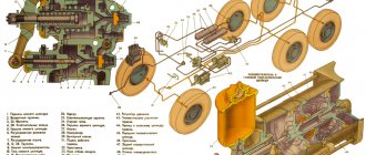
Rice. 7.16. Brake chamber type 20 with a spring energy accumulator: a - device; b — inhibited position; c — position when braking with the service brake system; d — position when braking the spare brake cficfeMOfl; o - position for mechanical release of brake mechanisms in the absence of air; 1 — camera body; 2 — pusher; 3 - piston; 4 — energy accumulator cylinder; 5 — power spring; 6 — screw of the emergency brake release mechanism; 7 — grenage tube) -8 — thrust bearing; 9 — diaphragm type 20; 10 — support disk; I - rod) 12 - return spring
Rice. 7.17. Engine brake-retarder mechanism: 1 - housing; 2— lever; 3 — throttle valve; 4 - damper shaft
If the tightness in the circuit of the pneumatic drive of the brakes of the parking (spare) brake system is broken or the pressure in the cylinder of this circuit decreases, the brake mechanisms of the wheels of the rear bogie of the vehicle will be automatically braked by spring energy accumulators. The movement of the vehicle in this case is ensured by the release of the brake mechanisms of the wheels of the rear bogie using pneumatic or mechanical release devices.
The device for mechanical release - a screw with a thrust bearing - is mounted in the pusher pipe of the spring energy accumulator. When the screw rotates (Fig. 7.16.5), the piston moves together with the pusher in the direction of compression of the spring, and the rod is released, which, under the action of the return spring, returns the adjusting lever with the expanding fist to the released position.