Since ancient times, hydraulic mechanisms have been used by mankind in solving various economic and engineering problems. The use of energy from fluid flows and pressure is still relevant today. The standard hydraulic motor design is designed to transfer the converted energy into force acting on the working link. The very scheme of organizing this process and the technical and structural nuances of the unit’s execution have many differences from conventional electric motors, which is reflected in both the pros and cons of hydraulic systems.
Mechanism design
The design of a hydraulic motor is based on a housing, functional units and channels for moving fluid flows. The housing is usually mounted on support posts or secured through locking devices with rotatable capabilities. The main working element is the cylinder block, which houses a group of pistons that perform reciprocating movements. To ensure the stability of the operation of this unit, the hydraulic motor is equipped with a system of constant pressure against the distribution disk. This function is performed by a spring with operating pressure from the working medium. The working shaft connecting the hydraulic motor with the output control is implemented in the form of a splined or keyed unit. Anti-cavitation and safety valves can be connected to the shaft as accessories. A separate channel with a valve ensures the removal of liquid, and in closed systems special circuits are provided for washing and exchanging working media.
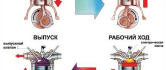
Operating principle of the hydraulic motor
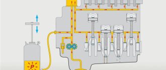
The main task of the unit is to ensure the process of converting the energy of the circulating fluid into mechanical energy, which, in turn, is transmitted through the shaft to the executive bodies. At the first stage of hydraulic motor operation, fluid enters the groove of the distribution system, from where it passes into the chambers of the cylinder block. As the chambers fill, the pressure on the pistons increases, resulting in the formation of torque. Depending on the specific design of the hydraulic motor, the principle of operation of the system at the stage of converting pressure force into mechanical energy may be different. For example, torque in axial mechanisms is generated due to the action of spherical heads and hydrostatic bearings on the thrust bearings, through which the operation of the cylinder block begins. At the final stage, the cycle of injection and displacement of the liquid medium from the cylindrical group is completed, after which the pistons begin their reverse action.
Connecting pipelines to the hydraulic motor
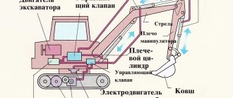
At a minimum, the fundamental design of the mechanism must provide for the possibility of connecting to the supply and drain lines. The differences in how this infrastructure is implemented largely depend on the valve adjustment technique. For example, the design of the hydraulic motor of the EO-3324 excavator provides for the possibility of dividing flows with a shunt valve. To control the hydraulic valve spools, a servo-drive control system with a pneumatic accumulator power source is used.
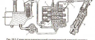
In conventional schemes, a drain hydraulic line is used, the pressure in which is regulated through an overflow valve. A distribution (also called cleaning and flushing) spool with an overflow valve is used in hydraulic drives with closed flows to exchange working fluids within the circuit. A special heat exchanger and cooling tank can be used as an addition to regulate the temperature of the liquid medium during operation of the hydraulic motor. The design of the mechanism with natural regulation is focused on the constant injection of liquid under low pressure. The difference in pressure across the operating hydraulic distribution lines causes the control spool to move to a position in which the low pressure circuit communicates with the hydraulic system reservoir through the overflow valve.
What is the price of a hydraulic motor?
There are many different brands on the market in our country that produce hydraulic motors of various types, the cost of which can vary from 100-200 to several thousand Euros. The popularity of this product has led to many Chinese counterfeits appearing on sale. Therefore, if you see a suspiciously low price, you should think about the fact that this product may be of low quality. is the official representative in Russia of such manufacturers as: Parker, M+S Hydraulic, Sauer Danfoss, Vickers, Sunfab, Sai, Italgroup, Casappa, Vivoil, Bosch Rexroth and other brands. Therefore, when purchasing a hydraulic motor from us, you can be sure that you will receive only original and reliable products with an official guarantee from the manufacturer.
Gear motor
Such engines have many similarities with gear pump units, but with the difference in the form of fluid removal from the bearing area. When the working medium enters the hydraulic motor, interaction with the gear begins, which creates torque. The simple design and low cost of technical implementation have made this type of hydraulic motor device popular, although its low performance (efficiency factor of about 0.9) does not allow its use in critical power supply tasks. This mechanism is often used in control circuits for attachments, in machine drive systems and in providing the functions of auxiliary parts of various machines, where the rated operating speed is within 10,000 rpm.
Low price of hydraulic motors in
Hydraulic motors, the price of which is optimal and lower than that of competitors, have advantages and disadvantages. Among the advantages noted:
- low weight and dimensions;
- presence of rotation speed adjustment;
- simplicity and ease of equipment management;
- fast start;
- affordable price;
- the presence of good indicators of resistance to frequent switching on and off.
The disadvantages of hydraulic motors include:
- low efficiency indicators;
- During operation, the working fluid heats up;
- the presence of breakdowns from low-quality or contaminated working fluid;
- the presence of negative effects from air that can enter the hydraulic system;
- unable to work in harsh climatic conditions.
You can get help in selecting a device from us. To do this, you can call a highly qualified manager by phone +74991139386 or write in the online form.
Gerotor hydraulic motors
A modified version of gear mechanisms, the difference of which is the ability to obtain high torque with small design dimensions. The liquid medium is serviced through a special distributor, as a result of which the gear rotor is driven. The latter works on roller rolling and begins to perform planetary motion, which determines the specifics of the gerotor hydraulic motor, the design, operating principle and purpose of this unit. Its scope of application is determined by its high energy intensity under operating conditions at a pressure of about 250 bar. This is the optimal configuration for low-speed loaded machines, which also place demands on power engineering in terms of compactness and design optimization in general.
Order travel hydraulic motor with fast delivery
At HYDRO-IMPULSE you can buy a new hydraulic motor, the price of which may be higher than that of used equipment, but at least:
- longer service life;
- the gap between repairs and maintenance is longer;
- has a guaranteed service life from the manufacturer;
- consumes less resources while the performance is greater than that of a supported motor.
Hydraulic motor, the price in our company is lower, because we supply the entire range ourselves, without the help of intermediaries.
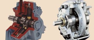
Axial piston hydraulic motors
One of the design options for a rotary-piston hydraulic machine, which most often provides for axial placement of cylinders. Depending on the configuration, they can be located around, parallel or with a slight slope relative to the axis of rotation of the piston group block. The design of an axial piston hydraulic motor also assumes the possibility of reverse motion, therefore, in configurations with serviced units, it is necessary to connect a separate drainage line. As for the target equipment operating such engines, it includes machine hydraulic drives, hydraulic presses, mobile work units and various equipment operating with a torque of up to 6000 Nm at a high pressure of 400-450 bar. The volume of the serviced environment in such systems can be either constant or adjustable.
The pump consists of a distributor disc, a rotating block, pistons, rods and a swashplate pivotally connected to a central pin. The disk has arc windows through which liquid is sucked in and pumped by pistons. Between the windows there are jumpers of width separating the suction cavity from the discharge cavity. When the block rotates, the cylinder holes are connected either to the suction cavity or to the discharge cavity. When the direction of rotation of the block changes, the functions of the cavities change. To reduce fluid leaks, the end surface of the block is carefully ground to the disk. The disk rotates from the shaft, and the cylinder block rotates along with the disk.
Rice. 1. Schemes of an axial piston pump: a - piston action, b - pump operation, c - structural, d - action of a fixed distribution disk; 1, 5—discs, 2—rotating block, 3—piston, 4—rod, 6—shaft, 7—window, .8—hole; a is the length of the full cross-section of the arc window
Rice. 2. Diagram of an adjustable axial piston pump: 1 - spring, 2 - piston, 3 - washer, 4 - plunger, 5 - shaft
The angle y is usually 12...15°, and sometimes 30°. If the angle y is constant, then the pump flow is constant. When the angle changes during operation, the stroke of the pistons 3 changes by one revolution of the rotor and the pump flow changes accordingly.
In an automatic variable axial piston pump, the flow regulator is a washer connected to the shaft and connected to the piston. A spring acts on the piston on one side, and pressure in the pressure hydraulic line on the other. When the shaft rotates, the washer moves the plungers, which suck in the working fluid and pump it into the hydraulic line. The pump flow depends on the inclination of the washer, i.e., on the pressure in the pressure hydraulic line, which, in turn, changes from external resistance. For low-power pumps, the pump flow can also be adjusted manually by changing the inclination of the washer; for more powerful pumps, a special booster device is used.
Axial piston hydraulic motors are designed in the same way as pumps. There are axial piston pumps and hydraulic motors with an inclined block and an inclined disk.
Fixed axial piston pump-hydraulic motor with an inclined block. The cylinder block receives rotation from the shaft through a universal joint. The shaft is driven by a motor and supported by three ball bearings. The pistons are connected to the shaft by rods, the ball heads of which are rolled into the flanged part of the shaft. The cylinder block, rotating on a ball bearing, is located at an angle of 30° with respect to the shaft and is pressed by a spring to the distribution disk, which with the same force is pressed against the cover, through the windows in which the working fluid is supplied and discharged. The lip seal in the front cover prevents oil leakage from the non-working cavity of the pump.
In such a pump, the axis of the cylinder block is located at an angle to the axis of the drive shaft, which determines its name - with an inclined block. In contrast, in axial pumps with an inclined disk, the axis of the cylinder block coincides with the axis of the drive shaft, and the axis of the disk, to which the piston rods are pivotally connected, is located at an angle to it.
Axial piston adjustable and non-adjustable pumps and hydraulic motors, widely used on domestic excavators, are distinguished by a unified design of the pumping section. The drive shaft is supported by three ball bearings: two angular contact and one radial. The inner rings of the bearings are held against axial movement by two spring rings, a bushing and a locking ring. The front cover has a lip seal resting on a bushing. The spherical seats of the shaft flange include seven connecting rods, which, together with the central tenon, are pressed to the shaft flange by a stamped plate. The cylinder block is fixed to the pin with a pin, the outer surface of which rests on the distribution disc. The tenon is supported on one side by a spherical head, and on the other by a bronze bushing pressed into the disk. Inside the cylinder block there are seven pistons rolled on connecting rods. Preliminary pressing of the cylinder block to the disk is achieved by disc springs.
When the axis of the shaft coincides with the axis of the tenon (as shown in the figure), the pistons do not reciprocate when the shaft rotates and do not suck in or pump out the working fluid.
Let us consider the designs of unregulated and adjustable pumps with one and two pumping sections, made on the basis of the described pumping section with an inclined block.
In an unregulated pump, the cylinder block is rotated so that the axis of the spike makes a certain angle with the axis of the shaft. Therefore, when the block rotates, the pistons suck in and force fluid through the disk channels. When changing the size and direction of inclination of the cylinder block, the power and direction of flow of the working fluid change. If you fix the angle of inclination of the cylinder block, the pump becomes unregulated.
Rice. 3. Axial piston unified pump-hydraulic motor: a - unified pumping section, b - unregulated pump-hydraulic motor; 1 - shaft, 2 - ring, 3, 9, 18 - bushings, 4 - plate, 5 - spike, 6 - disc springs, 7 - cylinder block, 8 - disk, 10 - pin, 11 - connecting rod, 12 - piston, 13, 14 — ball bearings, 15 — rings, 16, 20 — front and rear covers, 17 — seal, 19 — housing
Rice. 4. Axial piston unregulated pump-hydraulic motor with an inclined block: 1 - shaft, 2 - hinge, 3 - cylinder block, 4 - window, 5 - cover, 6 - disk, 7 - spring, 8 - piston, 9 - ball bearing, 10 - rod, 11 - seal
Rice. 5. Adjustable axial piston pump: 1 - shaft, 2, 13 - covers, 3 - housing, 4, 5, 6 - ball bearings, 7 - flange, 8 - connecting rod, 9 - axle, 10 - piston, 11 - cylinder block , 12 - distribution disk, 14 - rotary housing, 15 - central spike
The described design allows the pump to operate in hydraulic motor mode.
The adjustable pump has the ability to change the tilt of the block during operation. The pump housing can be rotated using a trunnion in relation to the fixed housing at an angle from 0 to 25°. The amount of liquid supplied by the pump is proportional to the angle of inclination of the cylinder block and the speed of rotation of the pump shaft. With this design, stepless control of the fluid flow is achieved regardless of the speed of the drive motor.
The force that must be applied to the trunnion may be such that direct control of the pump flow without the use of reinforcing devices becomes impossible. At high operating fluid pressure, pumps are used with mechanical and hydraulic amplifiers. Mechanical amplifiers can be either manually or electrically controlled. Hydraulic boosters are equipped with direct or remote control. Devices are also used that automatically change the angle of inclination of the cylinder block depending on the pressure in the hydraulic system (constant power regulators or power limiters).
The EO-3322D, EO-3323, EO-4321 A, EO-41 21 B and EO-4124 excavators are equipped with adjustable axial piston pumps, which consist of two unified pumping sections mounted in one housing. Such pumps are used to create two flows of working fluid. Full use of the drive motor power is ensured by a built-in power combiner, which distributes the power between consumers in such a way that the sum of these powers remains constant and equal to the installed drive power. The shaft receives rotation from the drive motor and transmits movement through the gearbox to the shafts of the pumping sections.
The rotating housings of the pumping sections are mounted on bearings and can be rotated around a vertical axis at an angle of 25°, thereby changing the pump flow. Both housings are rigidly connected to each other by the regulator traverse and can only be rotated synchronously under the influence of the power regulator.
Rice. 6. Double axial piston pump with power adder: a - hydraulic diagram, b - general view; 1, 7 - rotary housings, 2 - spool, 3 - set of two springs, 4 - traverse, 5 - pump shaft, 6 - gearbox, 8 - stroke limiter, 9 - cylinder block journal, 10 - regulator rod, 11 - screw minimum flow settings, 12 - washer
The power regulator is a two-stage spool placed directly in the pump housing. The areas of the regulator spool steps are equal. Discharge pressure is supplied to each stage from the pumping sections, i.e. P1 and P2. The spool is connected by pins to the cylinder blocks and receives the forces of the springs on one side, and the force created by the pressures P1 and P2 on the other. When operating at low pressure, the springs hold the housings at the greatest angle of rotation, ensuring maximum pump flow. When pressure increases, the spool compresses the springs, reducing pump flow. The springs and thrust washer are selected in such a way as to keep the specified drive power constant.
Advantages of axial piston pumps and hydraulic motors: compactness, high efficiency at high pressure, relatively low inertia, significant energy consumption per unit mass (in some high-speed designs up to 12 kW/kg).
The disadvantages of these pumps and hydraulic motors are the need for fine filtration of the working fluid, the complexity of manufacturing and the difficulty of ensuring a long service life of some parts (for example, the cylinder block bearing for pumps with a spool valve).
Radial piston pumps and hydraulic motors. The basis of the pump is a crank-slider mechanism, in which the role of a connecting rod is played by a stator coaxial to the O axis, and the cylinders are made in the rotor. When the rotor rotates around the O axis, which has eccentricity e relative to the O axis, the piston performs a rotational motion together with the rotor and a reciprocating motion relative to the rotor.
Rice. 7. Kinematic diagram of a radial piston pump: 1 - stator, 2 - rotor, 3 - channels
The liquid is supplied under the piston and removed from there through two channels made along the axis of the rotor. The liquid is displaced (pumped) when the piston rotates from point A to point C and when it moves to the center (axis). During operation, it is necessary that the pistons are pressed against the stator. This is achieved either under the action of springs placed under the piston, or with the help of sliders moving in the grooves of the stator, or through an auxiliary booster pump, thanks to which the pistons are pressed against the stator in the suction cavity of the pump.
In a hydraulic motor of a similar type, the pistons are pressed by the pressure of the liquid supplied under the pistons.
If the eccentricity size e in the pump is changed by moving the stator, the action of the suction and discharge cavities will be reversed. A change in eccentricity causes a corresponding change in pump flow.
Radial piston pumps are used to create pressure up to 25 MPa and flow from 5 to 500 l/min at a rotor speed of 6000 to 1500 per minute.
Radial piston hydraulic motors are similar in design to pumps and differ in purpose and principle of operation.
On EO-4321A excavators, a radial piston hydraulic motor is used to drive the turning mechanism, which develops a large torque on the shaft and is therefore called high-torque. The eccentric shaft of the hydraulic motor rests on two roller bearings, one of which is installed in the hydraulic motor housing, and the second in the lower cover. In constant contact with the shaft surface (kept from axial movement by thrust rings) there are five connecting rods that drive the pistons. The rubbing surfaces of the connecting rods and shaft are reliably lubricated by supplying oil from the hydraulic motor cylinder through filters pressed into the pistons, channels in the connecting rods and jets.
The lateral movement of the connecting rods is limited by the support plates. Attached to the top of the housing is a housing in which a hydraulic distributor is located that regulates the flow of working fluid into the hydraulic motor and drains it into the hydraulic system line. Through the coupling, the hydraulic distributor is constantly connected to the shaft and rotates with it.
Rice. 8. High-torque radial piston hydraulic motor: 1 - bolt, 2, 7, 13 - covers, 3 - hydraulic distributor, 4 - hydraulic distributor housing, 5 - jet, 6 - connecting rod, 8 - filter, 9 - piston, 10 - housing hydraulic motor, 11 — thrust ring, 12 — support roller bearings, 14 — shaft, 15 — valve, 16 — support plates, 17 — clutch
Two pipelines from the hydraulic system are connected to the hydraulic distributor housing. Fluoroplastic sealing rings are installed between the hydraulic distributor and its housing, as well as between the cylinders and pistons of the hydraulic motor. The internal cavities of the hydraulic motor are closed with covers.
An unloading drain valve is attached to the side of the body. At the lower protruding end of the eccentric shaft, the rotating gear of the rotation mechanism is rigidly keyed and meshes with the ring gear on the running frame.
The hydraulic motor works as follows. From the discharge pipeline, the working fluid under pressure enters the hydraulic distributor housing, and then into the hydraulic distributor. The discharge cavity of the hydraulic distributor is connected to the discharge windows in its central part, through which the liquid enters channels A, connected to the channels of the hydraulic motor housing. In this case, the liquid enters two or three cylinders of the hydraulic motor, depending on the position of the distributor windows relative to the holes of the housing 4. Under the pressure of the liquid, the pistons begin to move in the cylinders and rotate the shaft through connecting rods. As a result, the running gear of the mechanism rolls along the ring gear and the turntable of the excavator rotates relative to its undercarriage.
During operation of the hydraulic motor, some of the pistons move from the center, pushing liquid through the windows in the cylinders into the channels of the hydraulic motor housing and the distributor housing. From port B, fluid then flows into the hydraulic system return line. If the pressure of the liquid penetrating into the drainage line through the gaps of the ground cavities exceeds the permissible value, the valve piston compresses the spring and the liquid comes out through hole B. This indicates a decrease in the efficiency of the hydraulic motor.
Radial piston hydraulic motors
The most flexible and balanced hydraulic motor design in terms of torque regulation with the production of high values. Radial piston mechanisms are available with single and multiple action. The former are used in screw lines for moving liquids and bulk suspensions, as well as in rotating units of production conveyors. The radial piston device and the operating principle of a single-action hydraulic motor can be reflected in the following functional cycle: under high pressure, the working chambers begin to act on the drive cam, thus starting the rotation of the shaft, which transmits the force to the actuator. A mandatory structural element is a distributor for draining and supplying liquid, coupled with the working chambers. Multiple-action systems are distinguished by a more complex and developed mechanics of interaction of chambers with the shaft and liquid distribution channels. In this case, there is a clear divided coordination within the distribution system function across individual cylinder banks. Individual regulation on circuits can be expressed both in the simplest commands for turning on/off valves, and in point changes in the parameters of pressure and volume of the pumped medium.
Technical characteristics and features of the choice of hydraulic motors
To the question: “Where to buy a hydraulic motor at a low price,” many will answer: “HYDRO-IMPULSE.” In a store of hydraulic and attachments, where the entire range is certified and has a guarantee from the manufacturer. The cost of the hydraulic motor is lower, since it is formed without taking into account markups for the services of intermediaries. The site catalog presents a variety of models from domestic and foreign manufacturers, including:
- axial piston hydraulic pumps, hydraulic motors with an inclined block;
- keyed reversible hydraulic motors operating in both open and closed hydraulic systems;
- hydraulic motors with a splined shaft, with adjustable and unregulated volume, and other types.
When choosing a device, you need to pay attention not only to how much the hydraulic motor costs, but also to other, equally important aspects of the choice. Namely:
- technical characteristics of the device (rotation speed, operating and nominal pressure indicators, efficiency, power, performance indicators);
- type of device and method of motion transmission;
- features of the equipment (presence of reverse and the ability to change the working volume);
- features of the hydraulic distributor;
- model and brand of special equipment, and its design features, on which it is planned to install hydraulics - a hydraulic motor.
Since the same type of device cannot work effectively on different equipment.
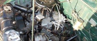
Linear hydraulic motor
A variant of a positive displacement hydraulic motor that creates exclusively incoming movements. Such mechanisms are often used in mobile self-propelled equipment - for example, in a combine harvester, the hydraulic motor supports the function of the actuators using the energy of the internal combustion engine. From the main output shaft of the power plant, energy is directed to the shaft of the hydraulic unit, which, in turn, provides mechanical energy to the grain harvesting organs. In particular, a linear hydraulic motor is capable of developing pulling and pushing forces over a wide range of pressures and working areas.
List
- MGP 100 Hydromotor Planetary Hydraulic
- MGP 125 Hydromotor Planetary Hydraulic
- Hydraulic motor A10FE10
- Hydraulic motor A10FE11
- Hydraulic motor A10FE14
- Hydraulic motor A10FE16
- Hydraulic motor A10FE18
- Hydraulic motor A10FM18
- Hydraulic motor A10FM21
- Hydraulic motor A10FM23
- Hydraulic motor A10FM28
- Hydraulic motor A10FM37
- Hydraulic motor A10FM45
- Hydraulic motor A10FM63
- Hydraulic motor A10VE28
- Hydraulic motor A10VE45
- Hydraulic motor A10VEC45
- Hydraulic motor A10VEC46
- Hydraulic motor A10VEC60
- Hydraulic motor A10VEC80