- home
- Media center
- Articles
- Air system ZIL 130
Menu
- News
- Articles
- Video materials
- Photo materials
- Publication in the media
- 3D tour
17.08.2020
Since the first release of the ZIL-130 in 1963, the model has undergone significant changes, which also affected the braking system. Manufacturers switched from an unreliable single-circuit system to a multi-circuit system, borrowed from another truck - KAMAZ. The Kamaz braking system for ZIL has become a practical and safe solution.
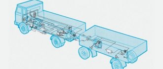
Air system for ZIL-130
The multi-circuit brake drive has been used in production since 1986. At the same time, a new designation came into effect - ZIL-431410, which is used mainly in technical documentation. For new models (manufactured after 1995), similar indices were used: UAMZ-43140 or AMUR-43140. This should be taken into account when searching for parts. Since 2014, the ZIL-130 has used three main independent air systems:
- Working – used to control movement and effectively stop a car, regardless of speed and weight.
- Parking - designed to ensure the immobility of the car in the absence of the driver (on a slope or horizontal surface).
- Spare – guarantees a complete stop of the vehicle in an emergency or in the event of a working failure.
Manufacturers of ZIL 130 prudently use the latest technical advances to ensure safety, because this model is used in the army and fire services.
Working circuit
The ZIL brake system, borrowed from KAMAZ, is the main one. The pedal in the driver's cabin of the ZIL-130 is connected to a two-section brake valve. The brake drive operates on a pneumatic basis. It is dual-circuit - with separate braking for the front and rear axles. The pneumatic brake circuits, including the parking and spare circuits, are equipped with a number of sensors to monitor their functionality. In case of defects they give visual (light) and sound signals.
Parking circuit
The mechanical drive provides the ZIL-130 vehicle with reliable fixation in the desired position. The brake chambers are installed on the rear axle and are additionally equipped with energy accumulators. The driver controls the system using the brake valve (a handle located to the right of the driver). During movement, the air compresses the springs of the electric accumulator, so that they remain motionless. When parked (after activating the lever), the air pressure decreases and power springs activate the brake mechanism on each wheel.
Spare circuit
The ZIL-130 spare air system is also connected to energy accumulators. It is activated using the brake valve of the parking model or automatically in the event of an emergency. Changing the air pressure on the power springs allows you to adjust the intensity of braking. In the KAMAZ brake system diagram for the ZIL-130, the spare circuit is considered the main advantage.
In the case of manual control, the ZIL-130 push-button valve provides control over the process, because compressed air is supplied to the energy accumulators in portions. If the parking system is partially or completely out of order, then in the spare system associated with it, mechanical devices are automatically turned on to brake the ZIL-130 when the pressure on the power springs decreases.
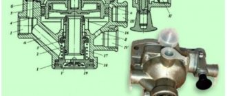
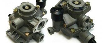
Stall Valve
(KS) (Figure 10) is designed to quickly discharge the brake line in the emergency braking position. The valve consists of a body, pos. 1, a cover, pos. 7, and an electro-pneumatic valve, pos. 8, installed on the valve cover. The housing contains a spring-loaded piston, position 2. The cavities above and below the piston are connected by throttle hole 3 with a diameter of 0.8 mm. There are 4 holes in the piston rod, which are located between the cuffs pos. 5 and 6 installed in the valve cover pos. 7. These holes connect the control cavity of the pressure switch with the atmosphere when the piston moves.
- 1 - body
- 2 - piston
- 3 - throttle
- 4 - throttle hole
- 5 - cuff
- 6 - cuff
- 7 - cover
- 8-EPV
Diagram of a multi-circuit air system
The ZIL-130 with the KAMAZ multi-circuit braking system is more reliable, because the driver can control the braking even in an emergency. For the parking and reserve circuits, only the compressor and energy accumulators are common.
The compressor (1) pumps air into the KAMAZ brake system of the ZIL. It is connected to the pressure regulator (20), which, in turn, is connected to the condensate freeze guard (21). The fuse is equipped with a control valve (3), through which, if necessary, diagnostic equipment can be connected to monitor the air pressure level. The same valves are located on other sections of the circuits.
Next, the air flow follows into the condensation air cylinder (10), where it gets rid of excess moisture. The cylinders are equipped with taps for draining condensate (12) and pneumoelectric sensors for determining the pressure drop in the circuit (13). From there the flow is forced into the double safety valve (19) or triple safety valve (14), where the first distribution takes place.
From the double valve (19) there is a line to the auxiliary air system air cylinder (23), which goes to the line to the control valves (24 and 25). On the other side, the valve (19) goes to the air distributor (7), which goes into the spare air system valve (6) with brake signal activation sensors (5). At the end of this closed line there are pneumatic cylinders that drive the spare circuit mechanisms (16).
From the triple valve, air enters the air cylinders of the ZIL-130 working brake circuit (9 and 11). In a critical situation, you can switch to parking. Then the air will flow through the parking circuit emergency brake release valve (8), then through the two-line bypass valve (31).
From there the path goes to the accelerator valve (27), from where it is sent to the parking air system valve (15) and the parking circuit air cylinder with a switch on sensor. After the cylinder there is a single safety valve (26), from which there is an outlet to: the connecting head (32), back to the accelerator valve (27), the control valve for the single-line trailer brake system (24), the control valve for the two-wheel drive air system of the trailer (25), parking circuit air cylinder with switch on sensor (22).
The connecting head (32) is used to combine the air systems of a ZIL-130 tractor and a trailer or semi-trailer. The trailer air control valves (24 or 25) are used separately, depending on the model. They are equipped with pneumatic-electric sensors to activate the braking signal (5), and they each go out to their own connecting head (32 and 33).
From the control valve for the trailer's dual-drive pneumatic system (25), there is also a line to the pressure limiting valve (4) with the control outlet valve (3). The brake chambers of the front wheels (2) are attached to part (4). From there there is a line to the two-section valve of the working system (18), where the line is connected back to the unit (25).
Separately from the two-section valve (18), there is a double line to the two-pointer pressure gauge of the working air system (17), to which the outlets to the air cylinders of the working circuit (9 and 11) are connected.
The brake force regulator (30) is protected by a two-line bypass valve (31). It is connected to the main line, goes to the control valve of the two-wheel drive pneumatic system of the trailer (25) and a closed circuit: brake chambers for the rear wheels (28), quick brake release valve (29), several control outlet valves (3).
The KAMAZ diagram of the ZIL-130 brake system duplicates the main parts. The working and parking lines operate completely separately, and the spare line remains as a backup. Each line is equipped with fuses and valves for precise control of air pressure.
Gearbox
(RED) (Figure 7) is designed to maintain a given pressure in the surge tank. The panel is equipped with a gearbox similar to the gearbox of the driver's crane 395. The gearbox consists of a housing, pos. 1 with feed valve pos. 2 and membranes pos. Z. The compressed air pressure is adjusted by rotating the stop pos. 4 acting on the spring pos. 5. A filter is installed at the inlet of the gearbox.
- 1 - body
- 2 - valve
- 3-membrane
- 4 — prop
- 5 - spring
Basic elements of a multi-circuit air system
The basis of the ZIL-130 air system is compressed air, which is pumped through a compressor. The air cylinders that are present in each circuit store a supply of compressed air in case of depressurization and are also called receivers.
The condensate freeze guard is a mandatory element in the ZIL-130 to prevent ruptures in system parts. An alcohol preservative creates an alcohol solution from condensation that freezes at a lower temperature. To do this, alcohol vapor is introduced into the air flow. It is rarely used, but the second option is popular.
The thermodynamic fuse is based on the supply of air cooled in the radiator, which liquefies the condensate and causes it to settle on the walls. Then the fuse is purged, removing excess.
The brake valve is used to pump pressure into the main actuators of the ZIL-130 in proportion to the force of pressing the brake pedal. To control the parking and spare air systems, an additional brake valve, made in the form of a handle, is used. These two circuits are interconnected and automatically interchangeable, so they can be controlled by a single lever.
Safety valves are located on important lines of the air system of the ZIL-130 truck. They must ensure consistent filling of the air system circuits and prevent the leakage of compressed air if one of the sections is depressurized. Thanks to their presence, even if there is minor damage, the system will be able to function normally.
Relay valves help increase speed. Energy accumulators contain a large supply of compressed air, which presses the power springs. When the parking brake is applied (for example), the accelerators help bleed air faster and speed up the response of the air system.
The brake force regulator should prevent the rear wheels of the ZIL-130 from locking when braking. According to the laws of physics, during braking the front wheels bear the main load, while the rear wheels are unloaded. The regulator helps to redistribute the load depending on the degree of deformation of the elastic suspension.
The emergency brake release capability is necessary to quickly release the vehicle from the brakes. In case of prompt action, compressed air can be pumped into the energy accumulators directly through the primary circuit. In a standard situation, pressure on the power springs appears only after the multi-circuit system has been filled.
The control valves for the air system of a trailer or semi-trailer for the ZIL-130 are shown in the diagram in full configuration. In some subtypes there may only be access to a single-circuit or double-circuit system.
The brake chambers in the ZIL-130 are actuators that directly affect the release devices of the brake mechanisms. Typically these are diaphragm type models.
Pneumatic boosters facilitate the operation of the compressor by increasing the pressure in the circuits to the required value. Thanks to their work, the expensive unit wears out more slowly. Sensors for monitoring the condition are located in the main components and brake chambers. This also includes a pressure gauge that monitors the pressure in the cylinders and in the brake chambers. Some models use a separate unit for each purpose.
Stabilizer
(ST) (the figure is also similar to the stabilizer of the driver’s crane 395. The stabilizer is designed to switch from increased to normal charging pressure without causing the brakes to operate.
The stabilizer consists of a body, pos. 1, with a valve, pos. 2, and a membrane, pos. 3. The cavity above the membrane is connected to the atmosphere by a throttling hole. The time of air flow through the throttle hole is regulated by a spring pos. 4, by rotating the stop pos.5.
- 1 - body
- 2 valve
- 3 - membrane
- 4 - spring
- 5 — prop
Operating principle of the KAMAZ type system
This sophisticated and efficient air system is used on most modern trucks because its operating principle makes it easier to operate, ensures quick stopping and prevents loss of control.
The ZIL-130 air system diagram is based on the action of power springs of electric accumulators. While they are exposed to compressed air (the main working fluid), they remain in a clamped state. This happens while driving or while the brakes are not applied in any way. Pressing the brake pedal or activating the parking brake valve (side handle) starts bleeding air from the system.
The pressure drops, the springs expand and act on the direct brake devices (pressing the pads against the brake discs). When the engine starts, you can pump air into the three circuits again with the compressor and continue on your way in safety. Amplifiers facilitate rapid air inflation, and an emergency brake release valve facilitates rapid deflation.
The ZIL-130 truck can be parked and released with the brakes even with the engine turned off, but within about ten minutes. The brake systems of ZIL and KAMAZ vehicles are equipped with receivers (air cylinders) in which a supply of compressed air is stored.
When the ZIL-130 driver stops the car and applies the parking brake, the air begins to slowly bleed out. But for some time there remains enough air in the cylinders to brake the car even without turning on the engine. But later you will have to start the car and wait until the compressor provides the required level of pressure.
The pressure regulator carefully monitors the condition of the parts, and in case of failure there are fuses. The multi-circuit air system for the ZIL-130 is completely safe and ideal for military trucks.
Control Circuit Switch
(Fig. 2) is intended for turning on and off the brake blocking device installed in the block of electro-pneumatic devices. The switch consists of a housing pos. 1 with a packet switch pos. 2, a piston pos. arrow, the second position (off) - by turning the key from the first position 90 degrees counterclockwise and the third position (change of cabins) - the key is turned another 90 degrees counterclockwise and removed from the socket. In the first two positions the key is locked. The driver must have one key for both cabs to exclude the possibility of control from an inactive cab.
Figure 2 — Driver’s crane control circuit switch
Advantages and disadvantages of air brakes
The KAMAZ multi-circuit system is a guarantee of safety, when duplicate circuits can replace the damaged area at the right time. But the basis of the brakes for the ZIL-130 was pneumatics.
Many car manufacturers prefer pneumatic systems for the following reasons:
- There is no need to replace the working fluid during maintenance: the air is simply released into the atmosphere every time you brake.
- Pneumatics are cheaper to maintain: the compressor requires minimal investment during use.
- The shock absorption of the system is reduced: the air does not damage the internal walls of the lines, so the hoses last longer.
- There is no risk of spoiling the working mixture: the hydraulic system uses various compounds that cannot be mixed and contaminated, and there are much fewer requirements for air.
- There is no danger from temperature changes: any fluctuations inside and outside are easily tolerated, a special device regulates the freezing of condensate.
- Minor damage does not threaten: with a small leak of compressed air, the brake can operate in the same mode.
- Trailer (semi-trailer) brake control: the system has special connectors for connecting a single-circuit or double-circuit circuit.
- Other elements can be connected to the system: door drive, sound signal, window regulator.
The main advantage of the pneumatic system is the low cost of spare parts and maintenance for the ZIL-130. Repairs can be carried out at a convenient time; even with severe breakdowns, there is at least one working circuit.
The pneumatic circuit also has disadvantages, which manufacturers are trying their best to correct. The ZIL-130 system operates slowly due to the need to pump three circuits with compressed air, but special amplifiers are already used. The units make the car heavier compared to its hydraulic counterpart, however, due to reliability and economy, most people choose pneumatics.
Mode Switch Tap
(KPR) (Figure 12) is a three-way ball valve and is designed to turn off electro-pneumatic valves when switching to backup control. The switch handle pos. 1 has two positions: remote control and backup control. When operating with a controller, the handle is installed perpendicular to the plane of the slab; when operating a backup tap, the handle is installed along the slab. For correct installation of the KPR handle, there is a corresponding marking on the panel.
1 - handle
Action
Basic faults
The ZIL-130 with the KAMAZ braking system is safe and reliable, but multi-circuit lines can also have malfunctions:
- Increasing braking distance. In normal condition, the size should not exceed 11m (in a dry area at a speed of 30 km/h). This indicates wear of spare parts or a violation of the tightness of the circuit.
- Pressure drop in the system. Compressor malfunction or area depressurization. It is necessary to urgently contact a specialist, although redundant circuits and fuses provide some time.
- Brake imbalance. It is characterized by the ZIL-130 truck skidding to the side during braking. The brake pads need to be adjusted.
- Difficulty releasing the brake. Many reasons (malfunction of elements). Requires urgent response.
- Wheel jamming. Breakage of tension springs, breakage of friction linings, jamming of pistons in wheel cylinders.
- Poor vehicle holding in place. Since the parking circuit is partially connected to the spare circuit, this situation is fraught with trouble. In most cases, the problem can be eliminated by adjusting the gap between the block and the drum or by washing and then lubricating the spare parts, but diagnostics must be carried out to exclude serious malfunctions.
- Trailer skidding when braking. Occurs as a result of a failure of the connection head, due to which signals are poorly transmitted to the trailer air system.
- Late response to pressing the pedal or clamping the brake valve. This may be the result of a sudden impact or gradual wear that has caused a defect in the air system.
The decision to use the KAMAZ scheme for the braking system in the ZIL-130 turned out to be very profitable. After the introduction of innovation, the demand for trucks increased greatly; at the moment it is considered a classic reliable vehicle for municipal and private services. As a result, the same principle was “borrowed” by many domestic and foreign manufacturers.
The multi-circuit pneumatic air system in the ZIL-130 allows you to save time and money on repairs, maintenance and management.
Crane Operator Controller
(Fig. 1) sector type is designed to control train brakes. Electrical signals from the controller are transmitted to an electronic unit located on the electro-pneumatic instrument unit.
The controller handle has 7 positions:
- -I - OVERCHARGING (with self-reset)
- -II - train (without “peak”)
- -III - closed without power
- -IV - closed with power supply
- -UA - slow braking
- -V - service braking
- -VI - emergency braking
Six positions of the controller handle are fixed, the first position is not fixed (overcharging) with self-return to the train position.
Figure 1 — Operator crane controller