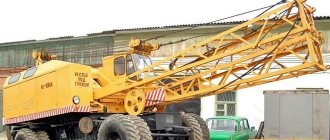
KS 4361A is a single-engine crane unit designed to perform operations related to the movement of cargo in hard-to-reach conditions. This device has gained recognition due to its endurance and ability to work on off-road, muddy ground and in cramped conditions. The advantages of the KS 4361A lie not only in its outstanding maneuverability, but also in its enormous capabilities in the construction and economic fields, as well as during search and rescue operations. The functions of this self-propelled vehicle have already been appreciated not only by developers during successful tests, but also by real users, for whom stable and uninterrupted operation over a long period of time is very important. This article presents the design, capabilities and characteristics of the KS4361A self-propelled pneumatic wheel crane.
Description and purpose
KS 4361A is a high-performance diesel crane with a torque converter. His responsibilities include moving a variety of cargo over certain distances. The model under consideration finds its application in the professional field, including the installation of buildings and structures, as well as the transportation of bulky technical equipment in horizontal or vertical positions. At the same time, the manufacturer says that there are no serious restrictions on the weight, type and dimensions of transported goods. Moreover, the equipment is in demand in logistics centers and other large organizations that require a replacement for low-power manipulators. The KS 4361A can also be used when removing rubble, and due to this, the truck crane is in deserved demand among the emergency services of the Ministry of Emergency Situations.
Transportation
Inside the construction site, the equipment moves independently, reaching speeds of up to 15 km/h. Movement with a payload mounted on the crane boom is allowed. In this case, the unit is located parallel to the longitudinal axis of the machine; the permissible speed does not exceed 3 km/h.
To deliver equipment to the work site, the method of towing with a rigid coupling is used. Trucks are used as tractors; road train speed is 20 km/h. When relocating, the gearbox is moved to the neutral position, and the hydraulic cylinders installed on the steering axle are turned off. Additionally, the driveshaft, which serves to drive the front axle, is removed.
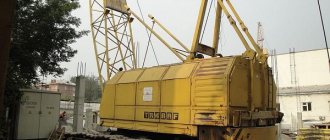
Delivery over long distances is carried out by rail. Before loading, the wheels are removed from the machine and the boom is disassembled into its component sections. The upper part of the knot is laid on the lower part. Loading is carried out by an assembly crane unit with a lifting capacity of at least 25 tons. If the machine includes additional boom elements, they are transported on another railway platform.
Technical and lifting characteristics
- Load capacity – 16 t
- Boom length – from 10 to 25 m
- Boom lifting speed – from 20 to 50 m/min
- Rotation speed of the rotary mechanism – from 0.4 to 2.8 rpm
- Entry angle – 15 degrees
- Load per wheel – from 3950 to 8350 kg depending on the load
- Load on front outriggers – 22340 kg
- Load on rear outriggers – 19040 kg
- Maximum speed – 333.3 m/min
- Turning radius – minimum 12 m
- Weight – 15 kgf/sq. m
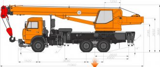
- Dimensions, mm: Length – 14500, Width 3800, Height – 3030.
| Pneumatic wheel crane KS-4361A description and technical characteristics |
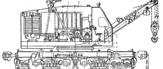
A self-propelled full-rotating diesel crane with a maximum lifting capacity of 16 tons is designed for construction and loading work with piece and bulk cargo on construction sites and warehouses. The crane has a hydraulic drive for supports and steering, and a lattice articulated-folding boom. The machine works with a main hook suspension on a boom of 10.5 m, 15.5 m, 20.5 m and 25.5 m, as well as an auxiliary extension (jib) of 6 m. With a boom of 10.5 m and 15, A 5 m crane with a load on a hook moves at a speed of up to 3 km/h. A feature of the kinematic scheme is the use of a torque converter, the output shaft of which is connected by a chain transmission to the rotation and movement reverse shaft. The operation of all actuators is ensured by a pneumatic system. For operation in tropical climates there is a special modification KS-4361AT.
| Overall dimensions of the pneumatic wheel crane KS-4361A |
Technical characteristics of the KS-4361A crane
| Maximum load capacity, t | |
| on supports | 16 |
| without supports on wheels and in motion * | 9 |
| Engine | SMD-14A |
| Engine power, hp | 75 |
| Hook lifting height, m | |
| with main boom | 10 |
| with full boom equipment | 25 |
| with additional equipment (extension + jib) | 30 |
| Lifting speed (stepless regulation) of load, m/min | |
| with a boom length of 10.5 m | 0…20 |
| with a boom length of 15.5 m | 0…35 |
| with boom lengths of 20.5 and 25.5 m | 0…50 |
| Turntable rotation speed, rpm | 0,4…2,8 |
| Maximum speed, km/h | |
| with a load on a hook | 3 |
| self-propelled without cargo | 18 |
| Smallest turning radius, m | 12,1 |
| Climbing angle of the track (without load) | 12° |
| Permissible wind speed, kgf/m2 | 15 |
| Structural weight of the crane, t | 23 |
| Maximum load on one wheel, kg | |
| when the crane is operating | 8 350 |
| when moving a crane with a 10.5 m boom | 3 950 |
| Maximum load on outriggers, kg | |
| front | 22 340 |
| rear | 19 040 |
| Overall dimensions, mm: | |
| length | 14 500 |
| width | 3 150 |
| height | 3 900 |
* Load capacity in motion is indicated with the boom positioned along the axis of the crane
Technical characteristics of the KS-4361A crane
| Hook lifting height, m | Load capacity, t | Reach, m | |
| on outriggers | without outriggers | ||
| Boom 10.5 m | |||
| 10.0 | 16.0 | 4.0 | |
| 10.0 | 9.0 | 3.8 | |
| 9.4 | 8.0 | 5.0 | 6.0 |
| 8.4 | 6.0 | 3.75 | 7.5 |
| 5.3 | 3.4 | 2.3 | 10.0 |
| Boom 15.5 m | |||
| 15.0 | 9.0 | 5.3 | 5.0 |
| 14.0 | 4.5 | 2.9 | 8.0 |
| 11.9 | 3.0 | 1.8 | 11.0 |
| 9.1 | 2.0 | 1.1 | 13.5 |
| Boom 20.5 m | |||
| 20.0 | 5.3 | 3.1 | 6.5 |
| 18.1 | 2.5 | 1.5 | 11.0 |
| 16.0 | 1.65 | 1.05 | 14.0 |
| 12.8 | 1.2 | 0.75 | 17.0 |
| Boom 25.5 m | |||
| 25.0 | 3.5 | 2.0 | 7.5 |
| 22.1 | 1.5 | 0.7 | 14.0 |
| 19.6 | 1.0 | 0.4 | 17.5 |
| 12.8 | 0.5 | 23.0 | |
| Running gear and movement mechanism of the KS-4361A crane | Portal crane KS-4361A | Replacement boom equipment for the KS-4361A crane |
| Photo gallery of the KS-4361A crane |
| Back to the page “Cranes. Descriptions and technical specifications" |
| The author of the site would be grateful for any information and photographs of this crane. Email |
| Copyright © 2002-2010 TechStory.ru |
home
Features of the device and operation
The KS-4361A truck crane installation is equipped with the following components: booms, hook and grab. These are moving parts that have different length parameters. For example, replacement booms are available in 15, 20 and 25 meter lengths. Together they form one main boom, in addition to which there is a 6 m long jib. The boom has a built-in tilt limiter onto the platform. KS-4361A is a modernized version of the popular KS-4361 crane, which has received fundamental changes that are noticeable both from the technical and external sides. The driver's cabin received an updated design, as did the appearance of the entire body. For ease of operation, the crane uses a time-tested pneumohydraulic control system. The operating speeds of the crane can be adjusted using a turbo transformer, which operates via a hydraulic system.
The running gear of the crane includes outriggers with screw jacks, which have so-called shoes at the ends. The crane unit moves around the site under its own power at a speed of 3 km/h, including together with the hook. Please note that when traveling over long distances, a self-propelled vehicle moves on a hitch or tow connected to a tractor. This is due to the fact that due to its large dimensions, the equipment is not approved for public roads. When transporting, the tug speed is no more than 20 km/h, and when turning it is reduced to 3 km/h. When transporting by rail, the crane is placed on a railway platform. The crane is loaded onto the platform using another (cargo) crane capable of lifting 25 tons.
Please note that all executive working parts of the crane are powered by a turbotransformer. To take off the power transmitted from the engine to the compressor, it is done using a V-belt drive.
The common shaft includes three drums - boom, auxiliary and cargo, which rotate freely on the shaft due to a ball bearing fit. In addition, the KS4361A model is equipped with a pneumatic chamber clutch with a friction connection. This type of connection allows you to open and close the connections of a part. The coupling includes a pulley, a tire and a pneumatic chamber.
Another structural element is the boom drum, on which band brakes are installed - closed and adjustable brakes. The design also includes a cylindrical final drive for the rear axle. The bevel gear is responsible for connecting intersecting shafts and regulating movement. A vertical shaft with a gear wheel is responsible for power take-off in the gearbox. The gearbox itself is a two-stage one, operating via a clutch.
Between the key parts of the crane installation - the engine and transmission - there is a torque converter that allows you to regulate speeds over a wide range, raise and lower loads, reverse the direction of the boom, and also change the speed of movement depending on the complexity and type of operation. The torque converter housing contains pump, turbine and idler wheels, which are driven by engine torque transmitted through the gearbox. The control system includes a compressor, refrigeration equipment, oil and moisture separator, receiver, control panel, pneumatic chambers and pipelines. The smooth rotation of the rotary mechanism is ensured by so-called flow regulators, and spools (valves) are used to control the valve mechanisms. So, depending on the type of task, a differential spool or a direct-acting spool is used.
The KS4361A truck crane is equipped with auxiliary elements that improve not only the functionality, but also the safety of the crane and the operator. In particular, let us pay attention to the complex of sensors and instruments that monitor the state of all operating systems and organs of a self-propelled vehicle. If any of the readings deviate from the norm (for example, a drop in oil pressure or overheating), the driver receives an audible signal indicating a malfunction. This will allow you to troubleshoot the problem in advance. The truck crane is also equipped with a protection system that is triggered when approaching power lines.
Device
The crane is based on a welded frame equipped with 2 bridges. The front steering axle is mounted on a balancer, which improves wheel traction on uneven roads. Changing the wheel alignment angle is performed by hydraulic power cylinders. The rear axle has a rigid suspension. A 2-speed manual transmission is mounted in the center of the frame. Cardan shafts are used to transmit torque to the axles. Axle gearboxes include spur and bevel gears.
On the side beams of the frame there are outriggers equipped with screw jacks. Installation and cleaning of units is carried out using the crane’s hydraulics. The use of supports increases the stability of the machine and increases the load capacity. A rotating platform is installed on the upper surface of the frame, on which all the working components of the machine are mounted. To connect the platform and frame, a 2-row ball ring with a gear ring is used.
The KS 4361A pneumatic wheel crane is equipped with a diesel power plant, including a 75-horsepower naturally aspirated 4-cylinder SMD-14A unit. The engine crankshaft is connected by an elastic coupling to a turbotransformer, which allows you to smoothly regulate the operating speeds of the machine. The pneumatic system compressor is installed separately from the engine. Torque is transmitted using a V-belt transmission. A fan is used to cool the compressor.
The transmission consists of cam and gear couplings equipped with a hydraulic drive. The nodes include rotation and movement mechanisms, respectively. To control the lifting units, a combined system with pneumatic and hydraulic drive is used. The winches are activated by pneumatic chamber couplings; a similar drive is installed on the reversible drive. Stopping and fixing of the drums is carried out by band brakes.
The standard lattice boom of the crane is 10.5 m long; It is possible to install additional extensions with a size of 5 m (up to 3 pcs.). Additionally, a fixed jib is mounted, having a length of 6 m. When using a jib, the length of the boom is limited to 20 m. There is a hinge unit at the base of the boom; a protective stop is installed to prevent tipping onto the platform.
The machine has a torque converter designed to drive the operating mechanisms of the crane.
A design feature is the installation of boom drive drums, a cargo hook and grab equipment on a single shaft.
The operator is placed in a closed metal cabin. The mechanisms are controlled using levers and pedals.
By special order there are cars with an insulated cabin equipped with an autonomous heater. The pneumatic system is equipped with a water vapor separator. The northern version of the crane allows you to perform work at air temperatures from -60°C.
Boats. Motors. Equipment and accessories
The KS-4361 crane is a diesel single-engine with a turbo-transformer (torque converter).
The set of working equipment includes a main boom with a length of 10 m
, a hook with a lifting capacity of 16
tons
and a grab with a capacity of 1.5
m3
, mounted on 10- and 15-meter booms.
Replaceable equipment is 15, 20 and 25 m
, obtained from the main boom by inserting 5 meter sections, and a 6
m
. The boom is equipped with a limiter that prevents it from tipping onto the platform when working at a minimum reach. The crane uses a mixed control system - pneumohydraulic. The winch and reverse shafts, as well as the drums, are activated using pneumatic chamber couplings; the direction of movement of the crane's turning and movement mechanisms is changed by a reversing mechanism and bevel gears. The inclusion of the reversing mechanism is also provided by pneumatic chamber couplings. The operating speeds of the crane are regulated over a wide range using a turbo transformer powered by the crane's hydraulic system.
Overall dimensions of the pneumatic wheel crane KS-4361
The running gear of the crane is equipped with outriggers with screw jacks having small shoes at the ends. The crane can move around the site under its own power, including with a load on the hook, at a speed of up to 3 km/h
.
Movement with a load on a hook is allowed on the platform with a boom of 10 - 15 m
, directed along the longitudinal axis of the crane.
Over long distances along highways, the crane is towed to a tractor using a coupling device. During the process of relocating the crane, the gearbox is set to the neutral position, the wheel steering cylinders are turned off, and the driveshaft of one of the axles is removed. The towing speed should not exceed 20 km/h
, and on slopes and turns the speed should be reduced to 3
km/h
.
The crane is transported by rail on a four-axle platform. Before loading the crane onto the platform, all pneumatic wheels are removed, the boom sections are separated, placing the upper section on the lower one. The crane is loaded onto the platform using an assembly crane with a lifting capacity of 25 tons
. If there are replaceable boom sections, they are laid on the second platform.
Technical characteristics of the crane KS-4361
| .. | 16 |
| .. | 3,75 |
| . without supports: | |
| ..at the smallest hook reach | 9 |
| ..at maximum hook reach | 2,5 |
| Hook reach, m: | |
| ..smallest | 3,75 |
| .. greatest | 10 |
| Hook lifting height, m: | |
| ..at the smallest hook reach | 8,8 |
| ..at maximum hook reach | 4 |
| Speeds: | |
| .. main hook lift, m/min | 10 |
| .. lowering, m/min | 0 — 10 |
| .. rotation speed of the turntable, rpm | 0,5 — 2,8 |
| .. self-propelled movement of the crane, km/h | 3; 15 |
| 213 | |
| 150 | |
| Smallest turning radius (outer wheel), m | 12,2 |
| Maximum angle of ascent of the track, degrees | 15 |
| Engine: | |
| .. brand | SMD-14A |
| .. power, hp | 75 |
| Wheel track, m: | |
| .. front | 2,4 |
| .. rear | 2,4 |
| Crane weight, t | 23,7 |
| Including counterweight, t | — |
Load capacity when moving and the climbing angle overcome during travel in transport position
*
— The load capacity is indicated with the boom located along the axis of the crane.
**
— The denominator is the permissible angle of inclination of the crane when working on outriggers.
Characteristics of the main and replaceable boom equipment of the KS-4361 crane
| Main boom length, m | 10 |
| Maximum length of extended boom, m | 25 |
| Length of unsteered jib, m | — |
| Tower boom equipment: | |
| .. maximum length of additional boom, m | — |
| ..maximum tower length, m | — |
| Grab capacity, m3 | 1,5 |
All actuators of the mechanisms on the KS-4361 crane are driven through a turbotransformer 35
. The landing of the drums of the boom, cargo and auxiliary (grab) mechanisms is on a common shaft; thus, one three-drum winch is used.
Power take-off from engine to compressor 32
carried out using a V-belt drive
43
-
44
and a cardan shaft
33
.
Rotation from the engine 34
to the turbotransformer
35
is transmitted through the coupling
20
, the output shaft of the turbotransformer is connected by a chain transmission
15
-
36
with the shaft
9
of the reversing mechanism.
Shaft 10
of the three-drum winch is connected to shaft
9
of the conical reverse gear by a gear
16
-
22
and a chain drive
18
-
23
, and gear
16
and sprocket
23
have a rigid fit on the shafts, and sprocket
18
and gear
22
rotate freely.
They are activated using pneumatic chamber couplings 19
and
14
mounted on the shafts.
Depending on which gear is engaged (chain or gear), shaft 10
is given direct or reverse rotation.
As can be seen from the diagram, the boom drum 13
, the main lift cargo drum
12
and the auxiliary lift cargo drum
11
have a free fit on the shaft and are kept from rotating by band brakes.
The drums are turned on using pneumatic chamber couplings; At the same time, the drums are released.
8
rotate freely on shaft 9 and are in constant mesh with gear
7
of vertical shaft
28
.
By alternately engaging the pneumatic chamber clutches of the gears 8
28
is ensured (rotation clockwise or counterclockwise).
Gears 6
, gears
24
and
26
are in constant mesh, and gear
26
is freely mounted on the shaft.
It is turned on using the cam clutch 27
, and the shaft
29
begins to rotate.
25
rotates together with the shaft , rolling along the ring gear
5
;
the rotary part of the crane rotates. Gear 24
, being in constant engagement with gear
26
, also rotates when it rotates, and since gear
24
has a keyed connection with shaft
30
, the shaft rotates with it.
Next, the rotation is transmitted using an equalizing clutch to shaft 31
, bevel gear
45
-
46
and shaft
55
of the chassis gearbox.
Gears 4
and
48
rotate freely on shaft
55
.
Their alternating activation is carried out using a cam clutch 49
.
Depending on which gear is engaged by the clutch, the speed of rotation of the shaft 53
, and, consequently, the speed of movement of the crane.
The gear 51
of the intermediate shaft is in constant mesh with the gear
50
of the output shaft
54
drives the front and rear axles
with the help of cardan shafts
41
and
52 The front and rear axles of the crane include differential devices that allow the right and left wheels to rotate at different speeds, which is very important when the crane moves along curved sections of the track. The input gear 40
of the main gear is in constant mesh with the gear
42
, sitting on the splines of the intermediate shaft.
From the intermediate shaft of the main drive, rotation is transmitted through gears 38
and
39
to the differential housing and through satellites (gears)
3
and sun gear
2
to the axle shafts of the crane wheels.
On the KS-4361 crane with a single-engine drive, when considering the kinematic diagram of its mechanisms, the concept of a main and auxiliary lift winch is not fully applicable, since the layout of the mechanisms with a single-engine drive does not allow one to clearly distinguish one or another winch; many elements of the kinematic chain of mechanisms are transmissions for a number of executive bodies. Therefore, this crane considers only the design of mechanisms directly connected to the executive bodies - the drums.
| Multi-drum winch | Band brake for cargo and grab drums | Adjustable boom drum brake |
On a common shaft 6
three drums are mounted: cargo
3
, auxiliary (grab)
18
and boom
5
.
All three drums have a ball bearing fit and rotate freely on the shaft. The drums are activated using pneumatic chamber couplings 1
,
7
and
14
, rigidly connected to the shaft, and are kept from free rotation or from rotation under the action of loads (loaded ropes) using band brakes.
The shaft rotates in double-row spherical bearings of supports 2
and
10
and is driven by a sprocket
9
or a gear
11
with a ball bearing support.
The wheel is driven using a pneumatic clutch 12
.
The reversal of the shaft is carried out by engaging a chain transmission using a pneumatic chamber coupling 19
mounted on the reversing shaft, or by engaging a gear wheel
11
.
The operating principle of a pneumatic chamber clutch is based on the friction of the tire against the surface of the drum pulley under the influence of compressed air. The type of coupling according to the nature of the connection is frictional; by the nature of the work and main purpose - to the class of controlled and coupling couplings that allow you to open and close the connections of the part. The coupling consists of a pulley 17
, a pneumatic chamber
16
and a tire
15
.
Air is supplied to the pneumatic chambers through rotating swivel joints from the ends of shaft 6
(through channels in it) and from the shaft to the chambers (through flexible hoses).
When compressed air is supplied through the hose 5
into the chamber, the latter expands and presses the friction belt with tire
15
to the inner surface of the drum pulley
3
.
The brake band is adjacent to the outer surface of the drum pulley. Tape 3
consists of two parts connected by a coupling bolt
1
.
One end of the tape is hinged with a pin on the scarf, the second end is connected to the eye 12
.
7
of the hydraulic cylinder
6
using a lever system .
The brake control is hydraulic. When you press the hydraulic cylinder pedal with your foot, the piston moves to the left and
turns the lever
11
7
and fork
9 .
In this case, eye 12
moves upward and the brake is tightened (the drum is braked).
If you remove your foot from the pedal, the hydraulic cylinder piston, under the action of spring 8
, will return to its original position (the drum will be released).
To ensure uniform withdrawal of the brake band from the drum pulley, spring 2
.
A brake of a similar design is installed on a clamshell (auxiliary) drum. The boom drum is equipped with two band brakes: permanently closed and adjustable. The eye 19
of the permanently closed brake is mounted on a bracket
18
;
the running end of the brake band is tensioned by a spring 4
.
16
is installed on the drum ;
with the help of pawl 15
the drum is kept from rotating.
If it is necessary to lower the boom, the pawl is disengaged from the ratchet wheel using rod 1
, lever
2
and pneumatic chamber
3
.
The stroke of the pneumatic chamber rod is limited by an adjustable (screw) stop 17
.
The controlled brake band, like the brake band of a cargo winch, consists of two parts connected by a coupling bolt. The uniform withdrawal of the belt from the drum is regulated by a guy spring 6
.
The brake eye is mounted on the bracket 10
using a shaft, on which a lever
12
, connected at one end to the eye of the brake band
14
, and at the other to the rod of the pneumatic chamber
9
. The tension of the brake band (braking of the boom drum) is carried out by spring 8 through rod 13, and the band is released using a pneumatic chamber. The main and auxiliary winches of jib cranes are equipped with special devices - rope handlers. They ensure correct laying of the rope drum in the grooves and prevent it from falling off the drum.
| Swing mechanism and slewing ring | Front axle | Transmission |
Rotation mechanism
is driven by a common motor for all crane mechanisms.
The bevel gear 27
of the reversing mechanism for rotation and movement of the crane is in constant mesh with the bevel gears sitting on the reversing shaft.
Loads on the vertical shaft 14
are perceived at the top by a radial ball bearing, and at the bottom by a thrust ball bearing and a double-row spherical roller bearing.
15
is rigidly mounted , which meshes with a gear wheel
8
, freely sitting on the vertical shaft
12
.
On the shaft 12
, in addition to the gear
8
, there is a brake pulley
13
, a gear coupling
10
and a gear
23
;
they are all rigidly connected to the shaft. During rotation of shaft 14
and with clutch
10
, the gear wheel rotates freely on shaft
12
and transmits rotation to gear
7
, which is rigidly seated on shaft
5
.
Together with the gear wheel 7,
the vertical shaft rotates and thus the power is transferred to the movement mechanism.
When clutch 10
12
begins to rotate and gear
23
begins to run around ring gear
22
;
the turntable begins to rotate relative to the central shaft 5
.
The ring gear has internal gearing. As can be seen from the diagram, the platform rotation gearbox simultaneously plays the role of a crane movement gearbox. The outer rings 17
,
19
are connected not to the frame of the undercarriage, but to the turntable;
the inner ring 22
is connected to the fixed frame of the undercarriage. Thus, the inner ring is stationary and plays the role of the base of the slewing bearing.
Front axle
crane KS-4361 - controlled, leading;
its suspension to the frame is balanced, which improves the grip of the wheels with the base on uneven roads. The transmission of power from the cardan shaft to the axle shafts 12
on the front axle is also carried out by a cylindrical main gear, as on the rear axle.
The inner wheels are mounted on a hub 6
, which is mounted using tapered bearings on a pin mounted in the frame
17
.
Using a flange 5
the hub
6
is connected to the axle shaft
4
.
The outer wheels are mounted on hub 2
6
using sliding bearings ;
thus, the outer wheels are not driven, as they have a loose fit. When a decrease in cross-country ability begins to affect the performance of the crane, the outer wheels are blocked with internal special drivers 18
installed on the flanges
5
so that the protrusion of the driver falls between the wheel rim stops.
The leash is fixed with bolt 19
.
The lower arms of the housings 17
are connected to each other by a transverse rod
14
of the steering linkage.
The upper arms of the housings are connected to the rods of the turning hydraulic cylinders, which are mounted on the axle housing bracket. Rotation of the drive wheels from axle shaft 12
to axle shaft
4
is transmitted through articulated joints
15
and
16
.
The rear axle
of the KS-4361 crane is driving. The bridge is of an automobile type, its suspension to the frame is rigid. It uses assembly units of the KrAZ vehicle, including the main gear with differential, axle shafts and brakes. The fastening of the running wheels is discless; it is carried out with clamps and rings. The main gear of the rear axle is cylindrical. The bevel gear serves to connect intersecting shafts and regulate movement.
On the KS-4361 crane, instead of the main friction-type clutch, a special hydraulic device is installed between the engine and transmission - a torque converter TRK-325. The torque converter provides stepless regulation of the speed of lifting and lowering a load, reversing the direction of movement, lifting small loads at increased speed, and changing the speed of movement depending on the resistance to movement.
Torque converter diagram TRK-325
The torque converter TRK-325 includes a housing in which the pumping unit is coaxially located 1
, turbine
2
and guide
3
(reactor) wheels.
The reactor is rigidly connected to the housing. The driving pump wheel receives movement from the motor shaft 4
, and the turbine (driven) wheel is connected to the driven shaft.
The radiator 5
serves to cool the working fluid passed through it using a gear pump
6
.
The transformer is equipped with a bypass valve, a filter and a hydraulic tank 7
, as well as an overrunning clutch.
At the same rotation speed of the turbine and pump wheels, the clutch connecting shafts 4
and
8
.
Turn off the torque converter by removing fluid from the system.
A brake controlled by the driver can be installed on shaft 8 To direct the movement of fluid in the system, a pneumatic pusher, spool valve, ejector and diffuser are used.
To the pneumatic control system
The KS-4361 jib crane includes the following elements: a compressor, a refrigerator and an oil and moisture separator, a receiver, a control panel with a pneumatic distributor, pipelines and pneumatic chambers mounted on the actuators of the crane.
Schematic diagram of the pneumatic control of the KS-4361 crane
The air is pre-compressed in the first stage of the compressor 13
, passes through the refrigerator and oil-moisture separator and is compressed in stage II to 0.6 - 0.7
MPa
, from where it enters receiver
16
and then through pipeline
17
to control panel
3
.
In the oil and moisture separator, the air is cleaned of moisture and oil, and then enters the second stage of the compressor. From the control panel, air flows through pipelines and special rotating joints 10
to the pneumatic chamber couplings
7
of the crane mechanisms.
When each mechanism is turned off, air from the pneumatic chamber couplings is released into the atmosphere. To quickly release the crane mechanisms, special valves 8
.
18
are used in the systems of the reversing mechanism and the rotation brake, as well as the movement mechanism . The crane mechanisms are controlled from the remote control using special devices - spool valves (valves). There are two types of spools: differential and direct acting. Differential spools are used for those valve mechanisms that require regulation of external forces when turned on. Such mechanisms are mechanisms with friction clutches used in cranes with a single-engine drive - an internal combustion engine. For mechanisms that do not require changes in pressure in the system, direct-acting spools are used.
Control cabin of a crane with a single-engine drive KS-4361
Electrical equipment
the KS-4361 crane serves to power internal and external lighting, light and sound alarms, and a load limiter; provides starting of the starting engine, heating and ventilation of the control cabin, heating of the diesel engine. The source of direct current is the G-66 generator, which is also designed to charge the 6ST-42 battery. The generator is driven by a diesel engine through a gear drive. To regulate the voltage and protect the generator, a relay regulator is provided, consisting of a voltage relay, a current limiter and a reverse current relay (prevents the battery from being discharged to the generator when the diesel engine is not running). Fuses are used to protect against short circuits. During the period when the diesel engine is stopped, the crane's electrical network is powered by a battery, which is also used to start the starting engine with an electric starter. The magnitude of the battery charging and discharging current is determined using an ammeter. The electrical system of the crane includes a set of converters installed on the engine, the oil tank of the turbo-transformer and the compressor. These converters make it possible, through appropriate devices, to control the temperature of water and diesel oil, the oil temperature in the turbotransformer, and the oil pressure in diesel and compressor systems. The limit positions of the boom are fixed by a limit switch, which acts on the electromagnet circuit. The latter controls the spool, which, when the boom reaches its extreme position and the switch is activated, turns off the turbo transformer and turns on the winch brake. The magnet receives power from the running diesel engine through a relay. The electrical circuit provides a control button that allows you to bypass the limit switch and return the boom to the working position, as well as turn on the load limiter when it is triggered. The control panel has a button to turn on the sound signal. The portable repair lighting lamp is switched on via a plug socket.
To limit the load capacity
The electric load limiter OGP-1 is used for the crane and automatic shutdown of the cargo winch. When the crane operates at minimum boom radii, a stop with flexible elements is used to prevent it from tipping onto the turntable.
Rope traction 2
passes through deflection rollers
1
on boom
4
and is fixed on the platform.
Springs 3
support the rope and prevent it from sagging. When the boom reaches the maximum angle of inclination (towards the turntable), the rope is tensioned and keeps the boom from further movement.
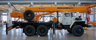
Truck crane KS-4361 and KS-4361A: technical characteristics, weight, lifting capacity, photo, boom length
The KS-4361 self-propelled full-rotating diesel crane with one engine has a lifting capacity of 16 tons. The machine is designed for construction and loading work with piece and bulk cargo at construction sites, warehouses, and factories.
The set of working equipment includes a main lattice articulated-folding boom 10 m long, a hook with a lifting capacity of 16 tons and a grab with a capacity of 1.5 m3, mounted on 10 and 15 meter booms. Replaceable equipment is extended booms with a length of 15, 20 and 25 m, obtained from the main boom by inserting 5-meter sections, and a non-steerable jib 6 m long. The boom is equipped with a limiter that protects it from tipping onto the platform when working at a minimum reach.
The KS-4361 crane uses a combined pneumohydraulic control system. The winch and reverse shafts, as well as the drums, are activated by means of pneumatic chamber couplings; the direction of movement of the crane's turning and movement mechanisms is changed by a reversing mechanism and bevel gears. The inclusion of the reversing mechanism is also provided by pneumatic chamber couplings. The operating speeds of the crane are regulated over a wide range using a torque converter powered by the crane's hydraulic system.
The running gear of the KS-4361 crane is equipped with outriggers with screw jacks, which have small shoes at the ends.
The crane is able to move around the site under its own power, including with a load on the hook, at a speed of up to 3 km/h. Movement with a load on a hook is allowed on the platform with a boom of 10 - 15 m, which is directed along the longitudinal axis of the crane.
Over long distances along highways, the KS-4361 crane is towed to a tractor using a coupling device. During the process of relocating the crane, the gearbox is set to the neutral position, the wheel steering cylinders are turned off, and the driveshaft of one of the axles is removed. The towing speed should not exceed 20 km/h, and on slopes and turns the speed should be reduced to 3 km/h.
The crane is transported by rail on a four-axle platform. Before loading the crane onto the platform, all pneumatic wheels are removed, the boom sections are separated, placing the upper section on the lower one. The crane is loaded onto the platform using an assembly crane with a lifting capacity of 25 tons. If there are replaceable boom sections, they are laid on the second platform.
The KS-4361 crane has an improved modification - model KS-4361A with a modified design of the body and driver's cabin.
Currently, the KS-4361 crane is not produced, but individual models can still be found on construction sites.
The self-propelled full-rotating diesel crane KS-4361A with a maximum lifting capacity of 16 tons is designed for construction and loading work with piece and bulk cargo at construction sites and warehouses.
The KS-4361A crane has a hydraulic drive for supports and steering, and a lattice articulated-folding boom.
The special equipment works with a main hook suspension on a boom of lengths of 10.5 m, 15.5 m, 20.5 m, and 25.5 m, as well as with an auxiliary extension (jib) 6 m long.
With a boom of 10.5 and 15.5 m, the KS-4361A crane with a load on a hook moves at speeds of up to 3 km/h.
The drive of all crane mechanisms is centralized. A feature of the kinematic scheme is the use of a torque converter, the output shaft of which is connected by a chain transmission to the rotation and movement reverse shaft. The operation of all actuators is ensured by a pneumatic system.
The KS-4361A crane is capable of successfully operating at subzero temperatures, and a special modification KS-4361AT is possible for working with tropical climates.
The KS-4361A crane is a modernized model of the KS-4361 crane with a modified design of the body and driver's cabin. All main technical characteristics of the machine correspond to the base model.
Serial production of the KS-4361A crane was started by the Yurginsky Machine-Building Plant in 1975. The crane is not currently being assembled.
Previously, we wrote about the technical characteristics of the KS-45726 truck crane.