Such protection will be required at a time when the towbar is not connected to the trailer.
If the pressure in the trailer line decreases, the lower piston, under the action of its spring, will rise and reopen the inlet valve. Some American cars use four-pin sockets. In the “Krepysh” the ground is carried out everywhere in bundles through the 3rd contact of the connector and distributed to all lamps except the fog lamp: for the fog lamp it is taken from the trailer through a ball. Connecting the towbar socket wires
Standard towbar socket This connection method is the most optimal, since it does not require intervention in the electrical wiring. The cavity above the piston, and, consequently, the outlet to the trailer brake line and the trailer brake control line is connected through the opened relief hole to the outlet to the environment. Starboard turn signal control signal. The S-type light socket is used to transmit reverse signals and fog lights.
Thanks Dmitry Buy Trailer They ensure the transmission of all signals from the car to the BTS. Cover First familiarize yourself with the location of all seven connectors. In MZSA trailers, the ground from the lights and the white ground wire of the wiring are connected to the trailer body.
The tracking action is carried out by a stepped piston.
KamAZ 5511 installation of a two-wire trailer brake control valve
KAMAZ how to remove the trailer crane
disconnecting the trailer brake control valve
How to remove the main brake valve on a Kamaz 5511 car
KamAZ trailer air distributor
Repair of trailer crane and generator.
Air leak from the brake valve KAMAZ ZIL PAZ MAZ KRAZ GAZ
Wabco air distribution valve.
KamAZ. State Customs Committee for the cabin.
Trailer brake control valve
KAMAZ accelerator valve
Trailer brake control valve.
Also see:
- KAMAZ 740 cylinder head bolt tightening diagram
- Gur KAMAZ 45143
- How to make the front of a KAMAZ truck softer
- Video tutorials on KAMAZ repairs
- Fire truck KAMAZ 43118 diagram
- Overview of the KAMAZ 5460 cab
- Dump truck KAMAZ 5510 technical characteristics
- Tie rod KAMAZ longitudinal rostar
- Tataria KAMAZ plant
- KAMAZ results of the first quarter of 2015
- Engine KAMAZ 11113
- How to properly adjust valves on KAMAZ video
- Standards for repairing KAMAZ vehicles
- KAMAZ is the master of whose engine
- How to change gears on a KAMAZ vehicle video
Home » Clips » KAMAZ how to remove the trailer crane
kamaz136.ru
Returning goods of inadequate quality
Returns of goods of inadequate quality are made exclusively within the warranty period..
If there are visible defects, you must send photographs or videos to e-mail: autofiltersmail.ru, in which the described defects are clearly visible and it is possible to identify the installed filter. In addition, the letter must contain the order number and VIN number of the vehicle. Photos should be taken during daylight hours or in a well-lit room. The indicated defects must be in focus. After viewing these materials, it will be determined whether the filter is defective or the feature/quality/property of this product.
If a defect is recognized, a replacement will be made. All shipping costs are the responsibility of the seller. In the case of a particular product or its properties, the product cannot be exchanged or returned.
If it is impossible to draw conclusions about a defect based on the materials sent, the store has the right to conduct an examination of the filter within 7 days (in accordance with Article 21, paragraph 1 of the PZPP). If, as a result of the examination of the product, it is established that its defects arose due to the fault of the consumer, the consumer is obliged to reimburse the seller for the costs of the examination, storage and transportation of the goods (Article 18, clause 5 of the Law of the Russian Federation).
Connection diagram for KAMAZ brake trailer valve
disconnecting the trailer brake control valve
KamAZ trailer air distributor
Air leak from the brake valve KAMAZ ZIL PAZ MAZ KRAZ GAZ
Wabco air distribution valve.
11.3531010-70 air distributor connection
11.3531010-70 air distributor
Repair of trailer crane and generator.
KUTP 1 TRAILER BRAKE CONTROL VALVE WITH SINGLE WIRE ACTUATOR ZTD
We install the KAMAZ accelerator on Foton 1093
air distributor 11.3531010-81.80 PAAZ connection
Also see:
- How to change gears on a KAMAZ dump truck
- KAMAZ dump truck 2012
- How to seal the casing on a KAMAZ
- Mode of part-time working KAMAZ
- Wedge disks for KAMAZ
- KAMAZ vehicles characteristics
- Installation of a Bosch fuel pump on KAMAZ
- Installation of a turbine on KAMAZ 53212
- KAMAZ trucks what category is needed
- KAMAZ design projects
- Disaster with KAMAZ
- Steering rod repair kit KAMAZ 4310
- Brake system of the KAMAZ 5310 vehicle
- Firefighter rapid response vehicle based on KAMAZ
- Air sensor KAMAZ
Home » Video » Connection diagram for the KAMAZ brake trailer valve
kamaz-parts.ru
Returning goods of proper quality
Returning goods of good quality is possible provided that they do not show signs of use. The contents, presentation and packaging must be the same as upon purchase. In case of damaged, dirty or missing packaging or other cases of “non-marketable” appearance of the Goods, the seller has the right to refuse to return the goods to the Buyer.
In accordance with the rules for the sale of goods remotely, enshrined in Article 26.1 of the Law of the Russian Federation of 02/07/1992 No. 2300-1 “On the Protection of Consumer Rights”, the Consumer has the right to refuse the goods at any time before its transfer, and after the transfer of the goods - within seven days .
KAMAZ trailer air distributor device | KAMAZ
KamAZ trailer air distributor
11.3531010-70 air distributor
Brake air distributor Design and operation
air distributor 100-3531008
disconnecting the trailer brake control valve
11.3531010-70 air distributor connection
Air leak from the brake valve KAMAZ ZIL PAZ MAZ KRAZ GAZ
air distributor 11.3531010-81.80 PAAZ connection
Valve KUTP 2
How does an air brake system work?
Also see:
- Cummins engine for KAMAZ power
- Removing timber on your KAMAZ
- Engine KAMAZ 570
- Front towing hook KAMAZ
- Video under the wheels of KAMAZ
- KAMAZ container truck body volume
- Mounting the mirror on KAMAZ
- KAMAZ 4 axle 20 cubic meters
- How to install a Cummins engine on a KAMAZ
- KAMAZ 65117 frame repair
- Laugh about KAMAZ trucks
- The largest KAMAZ plant
- Repair instructions for KAMAZ 53229
- Antifreeze went into KAMAZ oil reasons
- Oil scraper caps KAMAZ
Home » Selections » KAMAZ trailer air distributor device
kamaz136.ru
KAMAZ trailer braking system
KAMAZ brake system
KamAZ trailer air distributor
Brake systems KamAZ
disconnecting the trailer brake control valve
Pneumatic braking system
Air leak from the brake valve KAMAZ ZIL PAZ MAZ KRAZ GAZ
How the WABCO ABS pneumatic braking system works
Brakes jam on KAMAZ ZIL GAZ PAZ LAZ MAZ. Brake valve repair.
11.3531010-70 air distributor
CONVERTING BRAKE SHAFTS FOR BEARINGS (FRUEHAUF, BPW, ROR, SAF)
Also see:
- Replacing a KAMAZ vehicle engine
- Rem dimensions of KAMAZ shaft
- Buses on KAMAZ Ural chassis
- KAMAZ cylinder head
- KAMAZ cabs with sofa
- Transferring fuel from tank to tank on a KAMAZ
- Soars from the breather onto a hot KAMAZ
- There is no reverse gear on KAMAZ
- KAMAZ fits the platon
- Standard time for KAMAZ maintenance
- How to properly remove the box on a KAMAZ
- KAMAZ windshield wiper blade size
- Adjusting the steering wheel KAMAZ 53215
- Shock absorber KAMAZ 5312
- How much does KAMAZ consume when idling?
Home » Popular » KAMAZ trailer braking system
kamaz136.ru
_______________________________________________________________________________
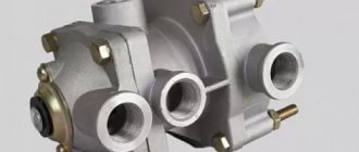
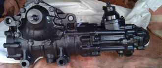
Trailer brake control valves for Kamaz vehicles
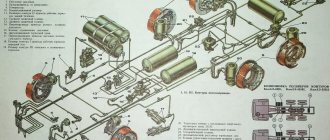
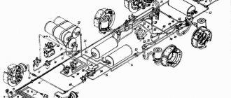
Trailer brake control valve with a two-wire drive The trailer brake control valve for Kamaz vehicles with a two-wire drive (Fig. 1) is designed to activate the brake drive of a trailer (semi-trailer) when any of the separate drive circuits of the working brake system of the tractor are turned on, as well as when spring energy accumulators are turned on drive of the spare and parking brake systems of the tractor. The valve is mounted on the tractor frame with two bolts. Fig.1. Kamaz trailer brake control valve with two-wire drive 1 - membrane; 2 - spring; 3 — unloading valve; 4 — inlet valve; 5 — upper body; 6 — large upper piston; 7 - spring plate; 8 — adjusting screw; 9 - spring; 10 — small upper piston; 11 - spring; 12 - medium piston; 13 — lower piston; 14 — lower body; 15 — outlet window; 16 - nut; 17 — membrane washer; 18 — medium body; I — output to the brake valve section; II - output to the parking brake system control valve; III - output to the brake valve section; IV - output to the trailer brake line; V - output to the receiver; VI - atmospheric outlet Between the lower 14 and middle 18 housings there is a membrane 1 clamped, which is secured between two washers 17 on the lower piston 13 with a nut 16 sealed with a rubber ring. An outlet window 15 with a valve is attached to the lower body with two screws, protecting the device from dust and dirt. When one of the screws is loosened, the outlet window 15 can be rotated and access to the adjusting screw 8 can be opened through the hole of valve 4 and piston 13. The Kamaz trailer brake control valve with a two-wire drive generates a control command for the air distributor of the trailer (semi-trailer) brake system from three independent commands. , acting both simultaneously and separately. In this case, a direct action command (to increase pressure) is sent to terminals I and III, and a reverse action command (to drop pressure) is sent to terminal II. The valve leads are connected as follows: I - with the lower section of the brake valve; II - with a manually operated reverse valve; III - with the upper section of the brake valve; IV - with the trailer brake control line; V - with car receiver; VI - with atmosphere. In the inhibited state, compressed air is constantly supplied to terminals II and V, which, acting from above on the membrane 1 and from below on the middle piston 12, holds the piston 13 in the lower position. In this case, terminal IV connects the trailer brake control line with atmospheric terminal VI through the central hole of valve 4 and lower piston 13. When compressed air is supplied to terminal III, the upper pistons 10 and 6 simultaneously move down. Piston 10 first sits with its seat on valve 4, blocking the atmospheric outlet in the lower piston 13, and then lifts valve 4 from the seat of the middle piston 12. Compressed air from terminal V, connected to the Kamaz receiver, enters terminal IV and then into the brake control line trailer mechanisms. The supply of compressed air to terminal IV continues until its effect from below on the upper pistons 10 and 6 is balanced by the pressure of compressed air supplied to terminal III on these pistons from above. After this, valve 4, under the action of spring 2, blocks the access of compressed air from terminal V to terminal IV. In this way, a tracking action is carried out. When the compressed air pressure decreases at port III from the brake valve, i.e. when braking, the upper piston 6, under the action of the spring 11 and the pressure of compressed air from below (in port IV), moves upward along with the piston 10. The seat of the piston 10 comes off the valve 4 and communicates pin IV with the atmospheric port VI through the holes of valve 4 and piston 13. When compressed air is supplied to terminal I, it enters under the membrane 1 and moves the lower piston 13 together with the middle piston 12 and valve 4 upward. Valve 4 reaches the seat in the small upper piston 10, closes the atmospheric outlet, and with further movement of the middle piston 12 breaks away from its inlet seat. Air flows from terminal V, connected to the Kamaz receiver, to terminal IV and further into the trailer brake control line until its effect on the middle piston 12 from above is equalized by the pressure on membrane 1 from below. After this, valve 4 blocks the access of compressed air from terminal V to terminal IV. In this way, a tracking action is carried out with this type of operation of the device. When the compressed air pressure drops at outlet I and under the membrane, the lower piston 13, together with the middle piston 12, moves down. Valve 4 opens from the seat in the upper small piston 10 and communicates terminal IV with atmospheric terminal VI through the holes in valve 4 and piston 13. With the simultaneous supply of compressed air to terminals I and III, the large and small upper pistons 10 and 6 simultaneously move downwards, and the lower piston 13 with the middle piston 12 - upward. Filling the Kamaz control line with the brake mechanisms of the trailer through terminal IV and releasing compressed air from it occurs in the same way as described above. When compressed air is released from port II (when braking with the spare or parking brake system of the tractor), the pressure above the membrane drops. Under the action of compressed air from below, the middle piston 12 together with the lower piston 13 moves upward. Filling the Kamaz trailer brake control line through terminal IV and braking occurs in the same way as when compressed air is supplied to terminal I. The tracking action in this case is achieved by balancing the compressed air pressure on the middle piston 12 and the sum of the pressure from above on the middle piston 12 and membrane 1. When compressed air is supplied to terminal III (or when air is simultaneously supplied to terminals III and I), the pressure in terminal IV connected to the trailer brake control line exceeds the pressure supplied to terminal III.
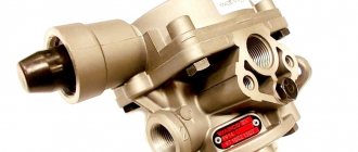
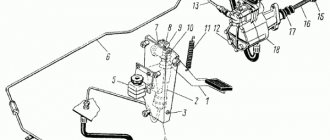
This ensures the leading action of the trailer (semi-trailer) braking system. The maximum value of excess pressure at terminal IV is 98.1 kPa (1 kgf/cm2); minimum - about 19.5 kPa (0.2 kgf/cm2), nominal - 68.8 kPa (0.6 kgf/cm2). The amount of excess pressure is regulated by screws 8: when the screw is screwed in, it increases, when turned out, it decreases. Trailer brake valve with a single-line drive Kamaz trailer brake control valve with a single-line drive (Fig. 1a) is designed to activate the brake drive of a trailer (semi-trailer) when the brake systems of the tractor are operating, as well as to limit the compressed air pressure in the pneumatic drive of the trailer (semi-trailer) in order to prevent the latter from self-braking during pressure fluctuations in the pneumatic brake drive of the Kamaz tractor. Fig.1a. Kamaz trailer brake control valve with single-wire drive 1 - spring plate; 2 — bottom cover; 3, 11 — thrust rings; 4 — lower piston; 5 — valve spring; 6 — exhaust valve seat; 7 — tracking camera; 5 — stepped piston; 9 — working chamber; 10, 17 — ring springs; 12 - top cover; 13 — protective cap; 14 — membrane spring; 15 — membrane spring plate; 16 - membrane; 18 — support; 19 — pusher; 20 — exhaust valve; 21 - inlet valve; 22 — body; 23 - spring; 24 — adjusting screw; 25 - lock nut; I - output to the receiver; II - output to the connecting line; III - release into the atmosphere; IV - output to the trailer brake control valve with a two-wire drive. The valve is installed on the vehicle frame and secured with two bolts. Compressed air from the receiver of the tractor vehicle is supplied to terminal I and passes through channel A into the cavity above the stepped piston 8. In the released state, the spring 14, acting on the plate 15, holds the membrane 16 together with the pusher 19 in the lower position. In this case, the outlet valve 20 is closed, and the inlet valve 21 is open and compressed air passes from outlet I to outlet II and then into the connecting line of the trailer. When a certain pressure is reached in port II, set using the adjusting screw 24, the piston 4 overcomes the force of the spring 23 and lowers, as a result of which the inlet valve 21 sits on the seat in the piston 4. Thus, in the released position, a certain pressure is automatically maintained in the trailer line, less pressure in the pneumatic drive of the tractor. When the Kamaz tractor is braking, compressed air is supplied to terminal IV and fills the sub-membrane cavity B. Overcoming the force of the spring 14, the membrane 16 rises upward together with the pusher 19. In this case, the inlet valve 21 first closes, and then the outlet valve 20 opens, and the air from the connecting line opens trailer through terminal II, hollow pusher 19 and terminal III in cover 12 goes into the atmosphere. Air leaves port II until the pressure in cavity B under the membrane 16 and in the cavity under the stepped piston 8 is balanced by the pressure in the cavity above the stepped piston. With a further decrease in pressure at port II, the piston lowers and moves down the pusher, which closes the exhaust valve, as a result of which the release of air from port II stops. In this way, a tracking action is carried out, and the trailer (semi-trailer) is braked with an efficiency proportional to the amount of compressed air pressure supplied to terminal IV. A further increase in pressure at port IV leads to the complete release of compressed air from port II and thus to the most effective braking of the trailer. When the tractor is braked, that is, when the pressure drops at terminal IV and in cavity B under the membrane 16, the latter, under the action of the spring 14, returns to its original lower position. The pusher goes down together with the membrane. At the same time, the exhaust valve closes and the inlet valve 21 opens. Compressed air from port 7 enters port II and then into the connecting line of the trailer (semi-trailer), as a result of which the trailer (semi-trailer) is released. Fig.2. Kamaz brake disconnect valve a - the valve is open; b - valve closed; 1 - plug; 2 - body; 3 — valve spring; 4 - valve; 5 — rod spring; 6 — rod with membrane; 7 - cover; 8 — pusher; 9 — handle; I - to the connecting head; II - from the receiver; III - into the atmosphere The Kamaz brake release valve (Fig. 2) is designed to shut off, if necessary, the pneumatic line connecting the tractor vehicle with the trailer (semi-trailer). Kamaz truck tractors are equipped with three disconnect valves: on side tractors - on the rear cross member of the frame in front of the connecting heads, on truck tractors - behind the cab on the right on a special bracket in front of the connecting flexible hoses. Each tap is secured with two bolts. The trailer brake control line is connected to terminal II, and compressed air is supplied to it through terminal I. If handle 9 is located along the axis of the valve, pusher 8 together with rod 6 are in the lower position and valve 4 is open. Compressed air from port I through the open valve and port II flows from the towing vehicle to the trailer (semi-trailer). When handle 9 is turned 90°, rod 6 together with the membrane rises upward under the action of spring 5 and air pressure. Valve 4 sits on the seat in housing 2, separating terminals I and II. The stroke of the rod 6, determined by the screw profile of the cap 7, is greater than the stroke of the valve 4. The rod 6 departs from the valve, compressed air from the connecting line through port II, the axial and radial holes in the rod 6 exits to the atmosphere through port III in the cap 7. After This allows the connection heads to be released. Fig.3. Connecting head KamAZ type “Palm” 1 - body; 2 - insert; 3 - seal; 4 - cover; 5 - clamp; I—connecting head; II - connection of the tractor and trailer heads Fig. 4. Connecting head Kamaz type A 1 - housing; 2 - valve spring; 3 - check valve; 4 - seal; 5 - cover; 6 — ring nut; 7 — rod; I - connecting head: II - connection of heads type A and B Kamaz connecting heads of the “Palm” type (Fig. 3) are designed to connect the lines of a two-wire pneumatic brake drive of a trailer (semi-trailer) and a tractor. On Kamaz onboard tractors, one connecting head, “Palm” type for the supply line, painted red (or with a red cover), is installed on the rear cross member of the frame on the right side (along the direction). Another Palm type connection head for the control line, painted blue (or with a yellow cover), is installed there on the left side. Both heads are installed in such a way that the connecting holes in them are directed to the right. On Kamaz truck tractors, the connecting heads are installed on flexible hoses and, after being disconnected from the semi-trailer, they are attached behind the cab on special brackets. The coloring of the heads is the same as on the onboard tractors. When connecting Kamaz heads of the “Palm” type, it is necessary to move aside the protective covers 4 of both heads. The heads are joined by seals 3 and rotated until the protrusion of the head fits into the corresponding groove of the other, that is, until the insert 2 is connected to the latch 5. Thanks to this, the tractor lines in case of spontaneous separation of the heads (for example, when the trailer is torn off). On Kamaz onboard tractors, the connecting head type A, painted black, is installed on the rear cross member of the frame on the left side (along the direction) so that the connecting hole in it is directed to the right. On KamAZ truck tractors, the type A connecting head is also painted black and mounted on a flexible hose. After being disconnected from the semi-trailer, the head is mounted behind the cab on a special bracket. When coupling a Kamaz tractor-trailer with a trailer, the protective cover 5 is moved to the side at the connecting head. The head of type A of the tractor is joined to the head of type B of the trailer with seals 4. In this case, the rod 7 of the head of type B enters the spherical recess of the valve 3 of the head of type A and tears off the valve from seal 4. After this, the heads are rotated until the protrusion of one head fits into the corresponding groove of the other head. The type B head lock fits into the groove of the type A guide head, preventing spontaneous separation of the heads. Sealing the joint of the heads is achieved by compressing the seals 4. When separating the tractor and trailer, the connecting heads are turned in the opposite direction until the protrusion of one head comes out of the groove of the other, after which the heads are separated. In this case, the valve, under the action of a spring, is pressed against the seal 4 and automatically closes the connecting line, preventing the release of compressed air from the pneumatic brake drive of the tractor vehicle. After disconnecting, close the head with lid 5.
_______________________________________________________________________________
_______________________________________________________________________________
_______________________________________________________________________________
- Clutch KamAZ-5320 and its components
- Repair of PGU and Kamaz clutch master cylinder
- Gearbox gearbox KamAZ 141
- Gearbox gearbox KamAZ ZF 16
- Gearbox 152 Kamaz with divider
- Gearbox gearbox 154 Kamaz
- Gearbox Kamaz-4308
- Clutch of a Kamaz-4308 car
- Clutch and gearbox KamAZ-65115
- Disassembly and assembly of Kamaz-4310, 55111, 43118 gearboxes
_______________________________________________________________________________
- Cylinder block, head and valves Kamaz-740
- Fuel system of Kamaz-740 diesel engine
- Adjustments and repairs of fuel injection pump Kamaz-740
- Drive axles of the Kamaz-4310 vehicle
- Repair of Kamaz drive axle gearbox
- Rear axle KamAZ-4308
- Axles and suspensions of Kamaz-65115 dump trucks
- Installation of Kamaz cardan shafts and axles
- Repair of Kamaz vehicle transfer case
- Kamaz power steering - adjustments and repairs
- Repair of Kamaz steering gear parts
- Steering parts Kamaz-4308
- Parts of the brake system Kamaz-4308
- Brake system and brake drive Kamaz
- Repair of brake valves and Kamaz compressor
- Suspension Kamaz-4310, 55111, 43118 and their parts
- Frame and suspension of the Kamaz-4308 car
- Cabin details and platform KamAZ-65115
- Cabin components Kamaz-4308
- Platform mechanism of Kamaz vehicles
- Klintsy KS 65719-5K truck crane based on KamAZ-6522 chassis
- Truck crane KC-35719-7-02 based on Kamaz-43118 chassis
- Truck crane Galichanin KC-55713-1K based on KamAZ-65115 6x4
- Ivanovets KS-45717K-1/1R truck crane based on KamAZ-65115 chassis
- Ivanovets KS-3577-3/4 truck crane on KamAZ-43253 4x2 chassis