see also
Comments 21
It’s normal for there to be so much dirt on the cylinder, how did you keep it cool? In general, the engine is not very good, weak and noisy, you need to install a Chinese one on it, but that will be a different matter)
We are made in the USSR. I borrowed a Chinese one from a neighbor as a replacement, I thought I wouldn’t be able to finish it - the cutters are small, everything bends and sag, I ate gasoline like an adult... We can’t beat the Chinese, we can’t)
I meant the Lifan 6 hp engine. It rushes at idle very confidently, judging by the reviews. And of course their cultivators themselves are so-so. I also have a mole with the original engine, only the piston on it died, it needs to be changed.
I thought that I wouldn’t find a magneto, so many years have passed and there are plenty of them... Most likely there is a piston one too and it costs a penny.
What oil do you use to dilute gasoline?
While there was an M8, I diluted it with it, now for two-stroke engines - STIHL, I read that it was not very good, but there is no other way.
They gave me something in the store for 2-stroke engines - the engine doesn’t want to work for a long time! I used to pour anything - autol - diesel and it worked! Now the seals need to be changed!
I read about oil seals. If it’s necessary, then it’s necessary. What you like is that everything can be taken apart on your knee.))
Maybe it will be useful to someone. Although, it’s unlikely. Such equipment can’t be found now, only China is around)
Whoever needs it will take a look)))
That's for sure. I still have a boat motor left over from the old days - “Salute”. He also lost the spark about 10 years ago. Now I looked at the documentation, and there is the same magneto)) The capacitor, by the way, is working, the winding of the high-voltage coil turned out to be short-circuited. This is so true)
Here's how to even)) Resolder the capacitor and the boat motor can also work)))
The condenser is working, the coil has broken.) I don’t know what the boat has yet.
Let's hope then that one of the two will work out)
Must! If it does not work out. I’ll install a new one, the path is already trodden))
Chainsaw magneto friendship?
Magneto from "Mole". But, most likely, it went and goes into many two-stroke engines.
Visually, the Ural chainsaw magneto is very similar. If possible, write down the markings, and I’ll compare them with my chainsaw magneto, maybe they’re identical.
see also
Comments 21
It’s normal for there to be so much dirt on the cylinder, how did you keep it cool? In general, the engine is not very good, weak and noisy, you need to install a Chinese one on it, but that will be a different matter)
We are made in the USSR. I borrowed a Chinese one from a neighbor as a replacement, I thought I wouldn’t be able to finish it - the cutters are small, everything bends and sag, I ate gasoline like an adult... We can’t beat the Chinese, we can’t)
I meant the Lifan 6 hp engine. It rushes at idle very confidently, judging by the reviews. And of course their cultivators themselves are so-so. I also have a mole with the original engine, only the piston on it died, it needs to be changed.
A device for checking the ignition unit of a chainsaw.
Currently, the market is saturated with chainsaws of foreign and domestic production, differing in appearance, size, power, but they all have one main detail in common - gasoline engines.
The ignition of the fuel-air mixture in the engine combustion chamber in previous domestic chainsaw engines was carried out by a spark obtained from a magneto, which was subsequently replaced by manufacturers with an electronic chainsaw ignition unit (MB-1 and MB-2).
Situations arise when a chainsaw fails to operate precisely because the electronic ignition unit is not working. How can you be sure of this? How to find the cause and eliminate it?
You can disassemble the ignition unit in parts and tinker with them, comparing them with working ones, or you can assemble a simple device that will help you determine a malfunction in the electronic ignition unit of a chainsaw in a couple of minutes.
Motoblock MB-1: frequent breakdowns of the unit and their solutions
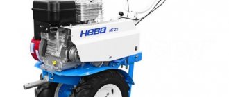
This walk-behind tractor can easily be called the “first-born” in Niva production. Of course, by now it has been modernized in many ways and has acquired a more modern design. With the help of such a unit, you can effectively treat the area in absolutely any weather. It will perform well both on soft sandy soil and on hard ground. And the cast iron cylinder liner ensures its reliability and long service life.
Now we will look at the most common cases of breakdowns of this unit. Usually all repair instructions can be found in the instruction manual, so if you still have it, you can safely use its instructions. But if this item is lost, then you can use our advice.
Let's look at the most common malfunctions of the MB-1:
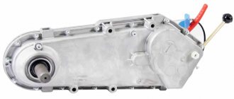
- If there is an oil leak on the output shaft, the first thing to do is remove the axle cover and replace the seal.
- What to do if the gearbox jams? In this situation, you need to disassemble the walk-behind tractor, where you need to replace the broken chain.
- If there is no kinematic connection inside the gearbox, then the broken sprocket in the block needs to be replaced.
- Gear malfunction: does not engage at all or does not shift. There may be several reasons for such a breakdown. The first is a destroyed switching pin. The second is that the threaded part of the shift knob is cut off. In these cases, we simply replace the defective parts with new ones.
- Oil leakage on the shift shaft. The first thing we do is check the oil level in the gearbox. If an excess of it is detected, then drain off the excess, and if on the contrary, top up.
- Wear of the shaft seal edge. Everything is simple here: we disassemble the gearbox and replace the worn cuff with a new one.
- Restoration of the overrunning clutch should be carried out as follows: remove the starter, take out the clutch, and grind off the grooves for the balls. You need to pour a little oil inside to minimize friction between the coupling and shaft. We install everything back.
How to make a device for checking the ignition unit of a chainsaw.
We have assembled a device that can accurately determine whether a chainsaw ignition unit is working or not.
The device consists of a horseshoe-shaped core assembled from a package of transformer steel strips, with a pulse coil and an excitation coil located on it.
The excitation coil (named according to our definitions) is designed to excite an alternating magnetic field into which the electronic ignition unit of the chainsaw being tested is placed.
The impulse coil (also named according to our definitions) supplies voltage to the electronic switching system (signal coil), that is, the electronic commutator.
Technique for detecting a chainsaw ignition malfunction with a device.
The principle is this: near the ends of the horseshoe-shaped core, the chainsaw ignition unit under test is placed, and the high-voltage discharge is checked at the output of the high-voltage coil.
For the MB-1 and MB-2 units being tested, the output from the pulse (signal) coil is unsoldered (in some cases this may not be done if its resistance corresponds to the reference one).
- The block is placed near the ends of the device in such a way that the core of the charging coil is located in the gap between the ends of the horseshoe-shaped core.
- One end of the wire from the pulse coil of the device is connected to the metal body of the ignition unit, the other end to a tap located at the signal coil of the electronic unit.
- An external conductor (high voltage wire) with a spark plug installed on it is connected to the output of the high-voltage ignition coil.
- The spark plug body is connected to the body of the electronic unit being tested. Instead of a spark plug, you can use a high-voltage spark gap with an adjustable gap or a regular break from the high-voltage wire to the body of the electronic ignition unit.
- The device is connected to an alternating current network.
- If the electronic switching unit is working properly, then a discharge will be observed at the site of the high-voltage gap (arrestor) or the spark plug, with a working high-voltage coil.
Repair and modernization of Magdino MB-22, MB-23.
Upgraded electronic unit MB-23.Since the beginning of the 90s, Vikhr-30 outboard motors began to be equipped with an MB-22 electronic ignition system (Magdino) instead of the outdated, less reliable MB-2 system. Soon, the Neptune-23E began to be equipped with a similar system, designated MB-23, and at first the electronic units of these Magdinos were identical, only the generator units located under the flywheel differed.
However, the new Magdinos also turned out to be not entirely reliable, since the manufacturer stubbornly continued to equip them with unpackaged thyristors with a KU-202M(-N) crystal. These thyristors are designed for a voltage of 400 volts, which is not enough for the normal operation of the ignition system, in which the operating voltages on the thyristor reach just this value. As a result, quite often the thyristors break through and the ignition fails. True, many electronics specialists have a different opinion about the cause of thyristor breakdowns: they say, the cord effect is to blame, and thyristors cannot withstand operating values of pulse currents. But this does not change the essence of the matter: KU-202 are unsuccessful thyristors for working in ignition systems.
In addition, the MB-23 electronic units of recent years are equipped with a circuit for limiting the maximum engine crankshaft speed. However, the limiter circuit is also unreliable, and often, due to the deviation of the parameters, it limits the speed to a significantly lower value than the rated 5000/min. As a result, the engine does not develop power. Buying a new unit only partly solves the problem, since there is a high probability of purchasing the problematic copy again.
The purpose of the proposed repair and modernization of Magdino is to eliminate the main reasons for the unreliability of standard blocks.
| Upgraded Magdino MB-23. Electrical circuit diagram. Explanations for the diagram: D1, D2 - KD 226 D; D3 - KD105B; Resistors - MLT-0.5; C1 - K73-17; Thyristor S1 - KU-709V (1000 V, 16 A); T1 - standard high-voltage transformer Magdino MB-23, L1 - standard charging coil (output - blue wire); L2 - standard control coil (output with green wire). |
The reliability of the unit is increased due to the use of elements with a good margin of operating voltage and current. Another requirement for parts - small dimensions - is dictated by the need to place the circuit in the “native” case, which, let me remind you, was designed for the use of an unpackaged thyristor and diodes. The list of elements includes proven diodes in a plastic case, a small-sized metal film capacitor and a thyristor in a small-sized TO-220 case. Domestic, inexpensive parts that are widespread in most of Russia are recommended. Of course, it is possible to use imported analogues. The closest analogue of the KU-709V thyristor is 16TTS12, but the range of thyristors is very wide and it is always possible to choose the appropriate one according to the parameters.
However, in Vladivostok there were no thyristors of the KU-709 series on sale, and the author purchased a foreign triac (thyristor of a symmetrical structure) MAS-16N (800 V, 16A) and a foreign metal film capacitor S 130 MPE 1 MKF, 630 V, which I hope , will only benefit reliability.
A speed limiter is not provided in this circuit; accordingly, the notorious yellow wire coming from the base of the magdino will remain unconnected.
| Drawing of PCB conductors. | Arrangement of elements on the board. |
The printed circuit board is designed for installation of parts recommended by the author. In the case of installing the domestic capacitor K-73-17, which is characterized by smaller dimensions, its left (according to the drawing) terminal is installed in the hole second from the edge of the board, and the connecting wire is soldered into the outer hole. Due to the design features of the cast housing of the MB-22(-23) electronic unit, the capacitor is placed on the side of the conductors. The grid pitch in the drawings is 2.5 mm.
Having prepared the parts, you can begin manufacturing the printed circuit board. There is no particular point in a detailed description of this widely known process, especially since, depending on the tastes and capabilities of each amateur, various technology options are possible. To the extent that the pattern of conductors can be obtained not by etching, but by cutting insulating grooves, and in general the board may not be printed, and the installation is carried out using suspended conductors. The author painted the conductors with ladies' nail polish using a standard brush and etched away the excess copper in a ferric chloride solution. To speed up etching, the following techniques were used: the solution was preheated to approximately 80°C in a microwave oven, the board was placed on the surface of the solution with the foil side down, and then floated on the surface due to surface tension forces. With this position of the board, insoluble sludge freely settles to the bottom of the container without slowing down the etching process.
| Printed circuit board with installed parts. | Cleaning the board from rosin residues with alcohol. |
After soldering the parts, stranded wires in vinyl chloride insulation are soldered into the corresponding holes. The color of the insulation must match the color of the wires of the factory unit. The photo shows a variant of wire colors corresponding to the Magdino MB-23. After soldering is completed, the board is thoroughly cleaned with alcohol to remove any remaining rosin so that the protective varnish adheres well to the surfaces in the future. It is not advisable to use stronger solvents, because Damage to the coatings of parts is possible.
| Electronic unit prepared for removal of the old board. | The process of softening the compound with a gas burner. |
The old printed circuit board with parts must be removed from the housing. The matter is complicated by the fact that the board is secured with a screw and then filled with epoxy compound in the case. Therefore, you have to resort to heating the block with the flame of a gas burner (you can also use an industrial hair dryer). Before heating the block, you should unscrew the high-voltage coil from it and bite off the wires.
It is better to heat the block in the fresh air, placing it on a stone or concrete block. Since epoxy resin releases harmful substances when heated, it is desirable that the wind direction be from the worker to the block. You should also wear safety glasses, as the compound may crack and fly into sharp pieces. The unit should not be overheated, because The goal is to soften the resin, not burn it!
After the resin has softened above the fastening screw, you should unscrew the screw and continue heating from different sides. At a certain point, the remains of the board and resin are easily removed from the body by striking the latter against a wooden log.
| Body cleared of compound. | Housing and lid with sealant applied in “drops”. |
If desired, you can install the board in the case and fill it with epoxy compound, similar to the factory version. However, since I used a MAC-16N triac, the threshold opening voltage of which is higher than that of thyristors, I had to provide for the possibility of selecting resistors in the control circuit. Therefore, I chose to seal the board with a coating of waterproof varnish and then install the cover with sealant. The good old BF-2 glue, which has proven itself well in this quality, was used as varnish. However, you should dry the board coated with this glue carefully, avoiding heat, so that bubbles do not appear. Of course, if possible, it is advisable to use a special varnish UR-231.
To fix the board in the case, one standard screw is not enough, so it was decided to clamp it in the area of the capacitor between two large drops of Kazan sealant applied to the bottom of the “bath” and the lid. Before installing the board, it is advisable to slightly dry the drops of sealant until they are tack-free, but so that the sealant inside remains mobile. This will ensure that the board is installed without distortion and can be easily removed for configuration.
| Coating the board by immersion in varnish. | Installing the board into the case. |
The board was installed in the case after being varnished twice with intermediate drying. After installing the board, it is useful to warm up the unit on a radiator to completely dry the varnish.
| Drying the board on the battery. | The finally assembled block. |
Finally, the lid and housing seat are coated around the perimeter with sealant and after some exposure they are assembled together. The holes between the cover and the housing where the wires exit are additionally coated. The red and white wires are soldered to the high-voltage transformer, the green and blue are terminated with standard half-connectors removed from the old wires. If old tips break, you can purchase new ones at a radio store.
Some thoughts on installing the upgraded Magdino on the engine. Since in the case of a homemade unit it is impossible to set the ignition timing using marks, you should initially install the generator unit under the flywheel in the middle position, and then select the optimal angle by trial runs at the highest achievable revolutions (or speed), or use the stroboscopic method.
Copyright © 1999 - 2005

