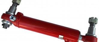
The performance of many types of power equipment, both industrial and domestic, is ensured by a device such as a hydraulic cylinder. Acting as a reciprocating drive motor, such a mechanism, with minimal energy consumption, ensures a full cycle of operation of power equipment used in construction, in various industries, in agricultural enterprises and in everyday life. Hydraulic cylinders are most widely used as the main element of equipment for pressing equipment, which is actively used to solve various problems.
A hydraulic cylinder is a volumetric hydraulic motor that converts the energy of fluid flow into mechanical energy
Hydraulic cylinder design - operation and principle of operation
A hydraulic cylinder is the simplest example of an engine.
The output (moving) link, which can be a rod, a plunger, or the cylinder body itself, carries out a reciprocating movement. The main parameters that characterize all hydraulic cylinders are the internal diameter, piston stroke, rod diameter and nominal pressure of the working fluid. Hydraulic cylinders come in several types: piston, telescopic, plunger, double-acting and single-acting. Based on the type of fastening, hydraulic cylinders are divided into models with hinged and rigid mounting.
A single-acting hydraulic cylinder exerts a force on the moving link, which is directed only in one direction (the working stroke of the cylinder). In the opposite direction, the moving link simply moves back under the influence of gravity or a return mechanism such as a spring. These cylinders have only one working plane.
Double-acting hydraulic cylinders have slightly more capabilities. They have two working planes, that is, they can create working forces on the output link in two directions. To ensure reciprocating motion, the liquid is alternately supplied under pressure into the cylinder cavity. When one of the cavities is filled with liquid, the other is connected to the drain. The hydraulic cylinder has two cavities: the rod cavity, in which the rod is located, and the piston cavity.
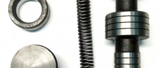
Now let's take a closer look at the design of a hydraulic cylinder using the example of a double-acting cylinder. The main parts that make up the cylinder are the hydraulic cylinder body, consisting of a sleeve (19) and a rear cover screwed to the sleeve, a front cover (9), which has a hole for the rod and is screwed onto the sleeve, a rod (18) with an eye (2 ), piston (15).
The figure shows the structure of a hydraulic cylinder. It consists of a spherical bearing (1), rod eye (2), wiper (3), sealing rings (4, 5, 8 and 13), cuff (6 and 14), cuff holder (7 and 12), front cover (9 ), locknut (10), damper (11), piston (15), nut (16), cotter pin (17), rod (18), cylinder liner with back cover (19), bushing (20) and wiper nut (21 ).
Using a piston with cuffs (14) and an o-ring (13), the piston and rod cavities are hermetically separated, and the force created by the pressure in the working cavity is transmitted to the rod. The piston is attached to the inner end of the rod using a nut (16), which is secured with a cotter pin (17). Cuff holders (12) keep the cuffs from moving along the piston axis. The front cover (9) is secured to the cylinder liner threads using a locknut (10). A bushing (20) is inserted into the cover (9), which serves as a guide for the rod. To avoid leakage of working fluid from the rod cavity, rings (8) are installed in the groove of the cover (9); cuffs (6), sealing rings (4) and (5) in the bushing are also used for this purpose. To avoid axial displacement when the rod moves, the cuff is restrained by a cuff holder (7). At the outer end of the cover there is a wiper (3), held in place by a nut (21), which is screwed into the internal thread of the cover. If the mechanism that is driven by the cylinder is deprived of stops that limit its stroke, which would fix it in extreme positions, then hard collisions between the piston and the hydraulic cylinder cover are possible. To soften these shocks, by damping or braking the piston as it approaches the cover, different types of damping devices are used. In the cylinder design, which is shown in the figure above, this function is performed by a damper (11) installed next to the piston (15) on the rod. The damper (11) softens the impact of the piston and the front cylinder cover at the end of the full stroke. The gap at the end of the rod stroke, located between the conical surface of the damper and the edge of the cover (9), through which the piston squeezes the working fluid from the rod cavity into hole “A”, decreases. During this process, due to the throttling of the liquid through the gap, the movement of the piston is inhibited.
Even if you know the structure of a hydraulic cylinder very well, repairing it at home or assembling your own cylinder is quite a difficult task. This requires special equipment and skills. Therefore, it is better to turn to experienced professionals with such questions. We specialize in the repair of hydraulic cylinders, as well as the manufacture of hydraulic cylinders according to your orders. Our company deals with the full range of work related to hydraulic cylinders. Our workers repair hydraulic cylinder rods, repair hydraulic cylinders for special equipment such as loaders, asphalt pavers, excavators, concrete pumps, truck cranes and manipulator cranes. We can also manufacture a hydraulic cylinder according to the drawings or samples you provide. We guarantee high quality and short terms of work.
Operating principles of a hydraulic cylinder
A hydraulic cylinder is a volumetric, cylindrical engine that supplies working fluid under pressure, driving any component of the hydraulic system. This mechanism is widely used in such types of special equipment as excavators, rollers, earth-moving, quarry machines, drilling rigs, machine tools, presses, cranes, etc.
Principle of operation:
In the standard case, the basis of the design is a liner - a pipe with a carefully processed inner surface, inside which a piston moves, which has rubber lip seals that prevent the flow of working fluid from the cylinder cavities separated by the piston. When the working fluid is supplied into the cavity, the liquid under pressure begins to move.
Components
The hydraulic cylinder consists of the following parts:
The chambers in the hydraulic cylinder must be sealed. To achieve this goal, special seals are installed on the piston - cuffs that prevent fluid from flowing through the piston. Also, the cuffs are placed on the axle box, here they act as seals. The axle box is also equipped with a wiper to prevent particles from the external environment of the device from getting into the inside of the cylinder.
Important: The seals on the piston do not work if there are roughness and scratches inside the liner. The inside of the liner is ground by special machines at the factory to achieve a relatively perfectly smooth state.
Types and characteristics of hydraulic cylinders
When purchasing a hydraulic cylinder, you should take into account a number of parameters and purpose. The main characteristics of these devices are:
- P —nominal pressure of the working fluid:
- D —diameter of the cylinder (piston);
- d —rod diameter;
- L —rod stroke.
Nominal pressure is the main indicator. The technical resource is determined by the operating mode of the engine at maximum pressure, therefore this indicator is also important. The maximum value of the rod speed should not exceed 0.5 m/s. If higher speed is required, special seals are used.
Depending on the purpose or scope of application, there are hydraulic cylinders for turning, lifting the boom, arm, bucket, blade, support, etc.
Depending on the principle of operation, hydraulic cylinders are single-acting and double-acting, telescopic and piston with a single-sided and double-sided rod.
Single acting hydraulic cylinders
— the extension of the rod is carried out due to the pressure in the piston cavity, and the return is made by the force of the spring. If the return is carried out due to the action of the drive of another hydraulic cylinder or the gravity of the lifted load, there is no need for a return spring, that is, the principle of operation in this case is similar to jacks.
Double-acting hydraulic cylinders
— during forward and reverse stroke of the piston, the force on the rod is created by creating pressure of the working fluid in the piston and rod cavities. In this case, the force during the forward stroke is slightly greater, and the speed of the rod movement is less than during the reverse stroke due to the difference in areas - the effective cross-sectional area.
Telescopic hydraulic cylinders
– have a structural similarity to a telescope. They are several cylinders inserted into each other in such a way that the body of one cylinder is the rod of another. They are available for both single- and double-acting.
Piston hydraulic cylinders
with a one-way rod are used most often in self-propelled machines. Double-sided - for turning the working equipment of mounted excavators. The working fluid is supplied into the cavity, both through the body and through the rod itself.
carries out repairs and restoration of hydraulic cylinders of all types and manufacturers on favorable terms in Moscow. We can also provide advice on the effective use of various models of hydraulic motors.
Hydraulic drives in industry. Part I
It is difficult to name a branch of modern industry where a hydraulic drive . High efficiency and great technical capabilities make it an almost universal tool used in various technological processes. Hydraulic drives are used in metallurgy and energy, in metalworking and the production of plastic products, in lifting and transport and woodworking equipment, in construction, in the production of agricultural machinery and in the automotive industry, etc. They are used in the processing of scrap metal, waste paper and municipal solid waste.
Drive selection
Drives in industrial production provide linear or rotational movement of parts and assemblies, raising or lowering them, moving with a load, maintaining a given speed of movement and acceleration, positioning, combining production processes, etc. Depending on the drive motor used, there are electric, hydraulic - , and pneumatic actuators.
Each of these drives has its own advantages and disadvantages. Therefore, when choosing equipment with one type of drive or another, you can focus on their consumer characteristics presented in Table 1. Table 1
| Options | Electric drives | Hydraulic drives | Pneumatic actuators |
| Energy costs | Low | High | Very high |
| Energy transfer | Over an unlimited distance at the speed of light | At a distance of up to 100 m. Speed - up to 6 m/sec., signal transmission - up to 100 m/sec. | At a distance of up to 1000 m. Speed - up to 40 m/sec., signal transmission - up to 40 m/sec. |
| Energy storage | Difficulty | Limited | Easily feasible |
| Linear movement | Difficult, expensive, low effort | Simple, high forces, good speed control | Simple, low effort, speed depends on load |
| Rotational movement | Simple, high power can be achieved | Simple, high torque, low revs | Simple, low torque, high rotation speed |
| Actuator operating speed | Depends on specific conditions | Up to 0.5 m/sec. | 2.5 m/sec. and higher |
| Efforts | High forces, no overload allowed | Forces up to 3000 kN, protected from overloads | Forces up to 30 kPa, protected from overloads |
| Positioning accuracy | Plus or minus 1 micron and above | Up to plus or minus 1 micron | Up to 0.1 mm |
| Rigidity | High - when using mechanical intermediate elements | High, since the oil is practically incompressible | Low because gas is compressible |
| Leaks and their consequences | None | Creates pollution and, if there are leaks, poses a fire hazard | No harm other than energy loss, explosion-proof |
| Environmental influence | Virtually insensitive to temperature changes | Sensitive to temperature changes | Virtually insensitive to temperature fluctuations |
Typically, the main advantages of a hydraulic drive include:
- high forces and large transmitted power per unit of drive mass;
- wide range of stepless speed control of the output link;
- precision positioning of parts;
- ease of control and automation;
- simplicity of protecting the drive motor and executive bodies of machines from overloads;
- reliable lubrication of rubbing surfaces when using mineral oils as working fluids.
And to the disadvantages:
- leakage of working fluid through seals and gaps, especially at high pressures;
- heating the working fluid, which in some cases requires the use of special cooling devices and thermal protection means;
- the need to ensure the purity of the working fluid during operation and protection from the penetration of air into it;
- fire hazard - in case of using flammable working fluid.
However, with the right choice of design of drive units and proper operation, some of the listed disadvantages can be eliminated or their negative impact can be significantly reduced.
According to the principle of operation, hydraulic drives are of dynamic type (hydraulic turbine, water wheel) and volumetric type. In volumetric type drives, liquid is pumped into the working chamber under pressure, as a result of which pistons, gears, plates, etc. are driven. In dynamic type hydraulic drives, only rotational motion is possible. In volumetric ones - both reciprocating or reciprocating motion ( hydraulic cylinders ) and rotational motion ( hydraulic motors ). hydraulic drives are mainly used .
Market and competition
The Russian market for hydraulic drives is assessed by most manufacturers as promising. Its traditional large consumers are agricultural and road construction engineering enterprises, as well as machine tool manufacturing.
According to experts, especially in connection with the implementation of the latest federal programs, agricultural engineering will remain a major consumer. We are talking about hydraulic systems intended mainly for servicing tractor attachments, and about hydraulic systems (50-60% of the drive engine power) - for harvesting machines, soil tillers, etc.
There are promising prospects in the production of road construction equipment using hydraulics : excavators, loaders, scrapers, bulldozers, motor graders, self-propelled jib cranes, and in the automotive industry - with fundamentally new hydraulic steering and other mechanisms.
In the machine tool industry, the prospects for the use of hydraulic systems are associated with: the use of gearless drives of feeds and spindles; with the production of machines with numerical control for contour and contour-positional processing; with the creation of mixed discrete control systems containing electrical and pneumatic elements; with increased reliability and accuracy through the use of relay and pulse-width control, with a feed system for multi-operational machines of increased accuracy and power with a servo hydraulic drive, etc.
The need for hydraulic drives used for the production of plastics, woodworking and other industries is not decreasing.
However, these prospects for domestic producers may turn out to be illusory, and a comfortable life may not happen. The reason is high competition with foreign companies. , foreign companies Denison Hydraulics, Ponar-Wadowice, YDAC, Vickers, etc. are taking root in the Russian hydraulic equipment
As for the Bosch Rexroth group of companies, it feels more than confident in the Russian market. And there is a reason. It is a world leader in hydraulics and drive technology. The share of products from this group of companies is about 20% of the world production of industrial hydraulic equipment for a wide variety of purposes. The production structure is dominated by hydraulic drives for metallurgy, hydraulic structures, energy, foundries, pressing equipment, injection molding machines, shipbuilding, oil production, metalworking, handling equipment. The companies included in the group, Bosch AT IHY and Rexroth Hydraulics, produce and supply industrial hydraulics , and hydraulics for hydraulic structures and metallurgical equipment - Rexroth Hydraudyne. Another supplier of mobile hydraulics is Bosch AT IMY. Rexroth Indramat and Bosch, etc. are engaged in complex control systems for machine tool building and general automation. Moreover, this group of companies represents on the Russian market other independent manufacturers of components for hydraulic drives - Voss, Pisner, Internormen, KTR.
Enterprises from CIS countries also continue to supply their products to Russia. For example, JSC "Kharkovsky" offers domestic consumers a fairly wide range of pumps: unregulated axial piston pumps of the HP2 type with a capacity of 632 to 1110 l/min. They are used in hydraulic systems of mechanisms of walking excavators, turbines of nuclear power plants, forging presses and powerful hydraulic machines; radial piston unregulated pumps type 50NR and sectional pumps type 50NS with a capacity from 5.5 to 423 l/min. Their scope of application is hydraulic presses, injection molding machines, nuclear power plants; adjustable radial piston pumps type 50НРР with capacity from 159 to 423 l/min. — for hydraulic presses, mining and woodworking equipment, metallurgical industry; adjustable axial piston pumps type NA..74M with a capacity from 57 to 200 l/min, which are used in rolling mills, injection molding machines, hydraulic presses, metallurgical industry, etc.
Price and more
Competition among manufacturers is also intensified by increasing supplies from abroad of equipment with already installed drives. We are talking about road construction machines and lifting and transport machines, metal-cutting, casting and pressing equipment, etc.
Under these conditions, domestic manufacturers choose various ways to combat competitors, which, in addition to using the traditional lever of lower prices, in the most general terms boil down to the following:
- import substitution - for example, Shakhtinsky OJSC mastered the production of equipment produced by Yerevan. This technique is used in the coal mining industry, for pressing plywood and naphthalene, in the construction industry, for the production of diamond powder, etc.;
- production of spare parts for equipment produced by Russian enterprises in previous years;
- production of spare parts and components for foreign equipment;
- modernization of hydraulic drives;
- production of products under licenses from reputable foreign companies. A number of domestic factories (Shakhtinsky, Yeletsk, Ulyanovsk) produce licensed products from Bosch Rexroth, which have made it possible to significantly raise the technical level of hydraulic drives for general machine-building applications. Solombalskaya, using the documentation and technology of the Finnish company Loglift, produces hydraulic manipulators SF-65, which, according to the manufacturer, combine Scandinavian quality and Russian prices. These hydraulic manipulators have been successfully tested for 15 years in all regions and in all climatic zones of Russia as part of URAL, MAZ, KamAZ, KrAZ vehicles, as well as TDT-55, TT-4, T-150K and Kirovets tractors; reduction of material and energy consumption of equipment, etc.
Naturally, with all this, domestic manufacturers not only continue to produce equipment that has earned a good reputation among consumers, but also increase production volumes and also create new ones. Naturally, in a competitive environment, product quality comes first for domestic manufacturers.
Components and Application
For the sake of systematic consideration, these products can be divided into several groups—components of industrial hydraulic systems that differ in their functional specificity. These groups are as follows: pumps, hydraulic motors, working fluids and filtering devices, control and regulating equipment, distribution equipment and various elements of hydraulic automation, pipelines and hoses, seals, etc. But, perhaps, the central place in this conditional classification is occupied by pumps. Table 2 presents some of the pump models produced by domestic enterprises, as well as typical areas of their application.
table 2
| Name of product | Application | Name of product | Application |
| Adjustable axial piston pumps | Pump - unregulated axial piston motors | ||
| NASF 63/22 | Five-axis CNC milling machine; winch; electric coating press; loader; blowing unit; electrode crimping unit | RMNA 32/35 | Forage harvester; grape harvester; injection molding machine; installation of continuous casting of cast iron; drilling and crane machine; lifting unit |
| 1NA4MF 63/22 | Single-station injection molding machine for thermoplastic materials with robot; press for making molds - for rubber technical products and cold extrusion for pressing and pressing parts of wheel pairs, electric machine rotors, blocks | RMNA 63/35 | Pipelayer; track machine; injection molding machine; mine drilling rig; injection molding machine; well repair unit; installation for testing oil wells; lifting and tractor installation; lifting and straightening machine |
| NARF 63/22 | Press for the production of particle boards; chip and sheet bending presses; presses for continuous rolling of metal and pressing of abrasives | MH 250/160 | Installation for repair of oil and gas wells; installation for drilling geophysical and structural exploration wells for oil, gas and water; installation for drilling water wells; locomotive; cold pipe rolling mill; hydraulic press |
| NAR74M-224/32SH | Guillotine shears; pipe bending machine | NAF 63/22 | Injection molding machine; broaching machine |
| NADP 63/22 | Machine for making building blocks from soil; hydraulic drive systems for rolling equipment; hydraulic power stations for welding equipment | MN 56/32 | Excavator; road roller; crane arm; car lift; motor grader |
| 1NADF 63/22 | Installation for welding large diameter pipes | MG 2.112/32 (310.2.112….) | Truck crane; municipal vehicles; forestry machines; railway cars |
| 1RNAM 32/35 | Hydraulic press is correct; chilling machine; casting machine; injection molding machine; hydraulic press with a pressure of 220 tons; broaching machine | Axial piston pumps, unregulated | |
| NPA 16/32 | Press | ||
| NPA 4/32-01 | Screw-cutting lathe; semitrailer | ||
| 1RNAS 125/35 | Floating crane; coal combine | NPA 32/32-01 | Hydraulic units |
Read about the features of pumps and other hydraulic drive elements in the next part of the article.
Valery Kaziev www.expert.ru
Hydraulic cylinder - device, operating principle, force calculation
The performance of many types of power equipment, both industrial and domestic, is ensured by a device such as a hydraulic cylinder. Acting as a reciprocating drive motor, such a mechanism, with minimal energy consumption, ensures a full cycle of operation of power equipment used in construction, in various industries, in agricultural enterprises and in everyday life. Hydraulic cylinders are most widely used as the main element of equipment for pressing equipment, which is actively used to solve various problems.
A hydraulic cylinder is a volumetric hydraulic motor that converts the energy of fluid flow into mechanical energy
Design features and principle of operation
The design of any hydraulic cylinder includes the following elements:
Plunger hydraulic cylinders are somewhat different in design, in which the plunger simultaneously performs the functions of a piston and a rod.
Hydraulic cylinder diagram
The operating principle of any type of hydraulic cylinder is based on the pressure of the working fluid on the piston. As a result of the impact on the hydraulic cylinder piston, the rod begins to perform cyclic work, transmitting force to the working unit of the equipment served by the device. Such a working unit, the functioning of which is ensured by a hydraulic cylinder, depending on the type and purpose of the equipment, can be a compacting platform, a bending or pressing mechanism, as well as a device of any other type that ensures the transmission of the force of the hydraulic cylinder to the final recipient of power energy.
Sliding hydraulic cylinder device
Since the force created by a hydraulic cylinder, as mentioned above, is formed due to the pressure exerted by the working fluid on the piston, the properties of this fluid have a significant impact on the efficiency of use, technical and operational characteristics of the cylinder itself. As a working fluid for piston or plunger type hydraulic cylinders, as a rule, a special oil is used, which must meet certain requirements for a number of parameters:
- chemical composition and density;
- temperature values at which the working fluid retains its original characteristics;
- the tendency of the working fluid to develop oxidative processes.
To operate hydraulic cylinders of various types and models, working fluid is pumped into their internal chamber using a manual or electric pump.
Features of plunger models
Take a look at the hydraulic cylinder catalogue. Among the power units of standard rod, telescopic, single-sided or double-sided ones, you will probably notice plunger modifications. Let’s say right away that they also have a wide range of applications and have proven themselves well in production equipment, such as lifts for heavy trailers. They contain, as the name implies, a plunger. Let us recall that this is a cylindrical rod, extended under the influence of the working medium pumped through the valve system. Under the weight of the object or due to external influences, the monolithic displacer returns to its original position and is recessed in the tube.
In addition to the base (sleeve) and plunger, the product includes a sliding support, sealing collars, and a wiper ring.
How are they different from piston
In plunger hydraulic cylinders, as you understand, there is no piston, that is, the rod is directly affected by the guide sleeve, which is displaced by the pumped medium. If there is no place for the piston, then there are no sealing rings; as a result, the inner surface of the cylinder may not contain a special chrome coating, and without it the drive is able to function properly. This is the main difference; other nuances relate to performance indicators. Plunger devices have a greater load capacity and are equipped with valve protection, which is activated when overloaded, but they have a significant disadvantage - the movement of the output link in one direction.
Main advantages
Among the obvious advantages, we highlight reliability, relatively simple production (no need to treat the inner surface, apply protective layers for perfect smoothness), and, accordingly, reasonable cost. But the advantages are not limited to this; here are some significant points:
- Power;
- Wear resistance;
- High efficiency with small dimensions;
- Durability;
- Possibility to choose products for different brands of cars.
Let's add simple maintenance to the above. Nothing special is needed. Those who have dealt with hydraulic systems are familiar with the basic requirements: maintaining fluid levels, avoiding overload, and periodically replacing seal materials.
Main varieties
Different types of hydraulic cylinders are distinguished according to a number of parameters. So, depending on the number of positions that the device’s rod can occupy, it can be:
Depending on the nature of the stroke of the piston and rod, the following types of hydraulic cylinders are distinguished:
- single-stage devices;
- telescopic hydraulic cylinders.
Operating principle of various types of hydraulic cylinders
A single-acting telescopic device or a double-acting telescopic hydraulic cylinder is used in cases where it is necessary for the rod overhang to exceed the length of the hydraulic cylinder body. A telescopic hydraulic cylinder consists of several cylinders that are nested one inside the other, and the body of each subsequent cylinder is the rod of the previous one.
According to the method of fastening the rod and sleeve, hydraulic cylinders can be divided into the following groups:
- 1. On lugs with articulated bearings
- 2. On the eye with a spherical bearing and a journal on the body
- 3. On the eye with a hinged bearing and with the preparation of the rear cylinder cover for welding with the mating structural element
- 4. With the outer end of the rod prepared for welding with a mating part and on the eye with a hinged bearing
- 5. With the preparation of the outer end of the rod for welding with the required part and with fastening
- 6. With preparation for welding of the outer end of the rod and the rear cover of the hydraulic cylinder with the required parts
Depending on the manufacturer, the layout of the elements of this circuit may vary.
Here are examples of hydraulic cylinder designations:
TsG-125×80×1000.11 manufactured by JSC "ELETSGIDROAGREGAT" where 125 piston diameter, 80 rod diameter, 1000 working stroke, 11 design: lugs with articulated bearing on the body and rod
G-150.125.56.400G manufactured by JSC "SDM" Orel where piston diameter is 125, rod diameter is 56, stroke is 400
Moreover, the plant that produces the machine often uses its own separate product markings, for example: the G-150.125.400G engine also has the designation TO-30.44.10.000, which is used directly by the plant that produces the TO-30 loader.
All features of markings and symbols must be reflected in the corresponding accompanying documentation of a particular hydraulic cylinder manufacturer.
Main characteristics
When selecting a hydraulic cylinder, you should focus on its parameters, which can be divided into two main groups:
- characterizing the power potential of a hydraulic cylinder;
- related to the design features of the device.
From the point of view of power potential, the most important parameter of a hydraulic cylinder is the force it creates. Various models of hydraulic cylinders offered on the modern market are capable of creating pressure, the value of which varies in the range from 2 to 50 tons, while the minimum forces (up to 10 tons) are created by single-sided hydraulic cylinders, and the maximum by double-sided ones.
Hydraulic cylinders are available with gravity, hydraulic or spring return, as well as with a locking nut
Knowing the dimensions of the hydraulic cylinders, as well as the pressure that the working fluid exerts on their piston, it is possible to calculate the force created on the rod. In order to calculate a hydraulic cylinder in order to determine the force created by the rod, it is enough to multiply the values of the pressure of the working fluid and the area of the piston on which it acts. When performing such calculations, it is important to take into account friction losses, for which a special coefficient is used, which is substituted into the formula used.
Calculation of the main parameters of a hydraulic cylinder
To determine the geometric parameters of the selected device, it is not necessary to study the drawings of the hydraulic cylinder; to do this, it is enough to understand its markings. Thus, the marking of hydraulic cylinders, the requirements for which are specified by the provisions of the relevant GOST, contains information about the following geometric parameters:
- diameter of the piston working surface;
- diameter and stroke of the pump rod.
In addition, the marking of hydraulic cylinders contains information about:
- design of the pump;
- type of device (single- or double-acting).
Based on the designations of hydraulic cylinders, you can also determine for what climatic conditions a particular model is intended.
Marking of piston hydraulic cylinders according to OST 22-1417-79
The efficiency of a hydraulic cylinder is ensured not only by its design and technical parameters, but also by the characteristics of the elements of the hydraulic system working in conjunction with such a device. A hydraulic cylinder, consisting of a working chamber, piston and rod, requires a supply of working fluid in the required volume and under a certain pressure, the degree of purity and other characteristics of which must meet certain requirements.
Compliance with such requirements is ensured by elements of hydraulic systems, the selection and maintenance of which, as well as the selection of the hydraulic cylinder itself, should be given special attention.
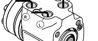
Designation on the diagram of the excavator filter and elements for monitoring fluid parameters
To clean the working fluid, a drain filter with a bypass valve is installed in the hydraulic system of the excavator. The pressure at the inlet to the filter is controlled by an MH3 pressure gauge; the pressure value can be used to judge whether the filter element is clogged.
The pressure at the pump outlet is controlled using pressure gauges МН1 and МН2; the pressure gauges are connected to the excavator hydraulic system through valves.
The temperature of the working fluid is controlled by thermometer T1.
Source
What is a hydraulic cylinder?
A hydraulic cylinder is a mechanism of the hydraulic system, which is an integral working element of equipment for various purposes, the main principle of which is the transformation of hydraulic force into mechanical force - the output link. The process of converting force is carried out using reciprocating or rotary-rectilinear movements.
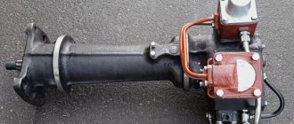
What does a hydraulic cylinder look like?
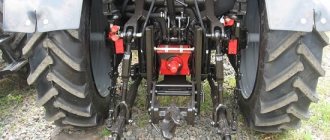
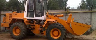
The hydraulic cylinder is used in the manufacture of construction, road and agricultural equipment that has drives for raising and lowering mounted structures - manipulator cranes, buckets, shovels, seeders, hydraulic hammers, plows, buckets, etc. Hydraulic cylinders are also often used for wood splitters.
Excavator hydraulic diagram
The hydraulic diagram of a single-bucket mounted excavator is shown in the figure.
Such excavators are installed on tractors.
The liquid from the unregulated pump H1 flows to the multi-spool distributor P1, which controls the hydraulic cylinders for raising and lowering the boom, rotating the bucket, and rotating the handle.
Hydraulic distributor P2 controls the hydraulic cylinders for raising and lowering the boom and turning the working equipment.
As can be seen from the hydraulic diagram of the excavator, distributor P3 is located in series, after hydraulic distributor P2. Spools P3.1 and P3.3 allow you to control the hydraulic cylinders of remote platforms; spool P3.2 is necessary to control the hydraulic cylinder for raising and lowering the bulldozer blade; to adjust the speed of lowering the blade, a throttle DR1 is installed in the hydraulic system.
The distributors are equipped with safety valves that limit the maximum pressure in the system.
Types of hydraulic cylinders
Product variants require different configurations and application options. And for convenience, they are usually divided into specific types.
By type of direction of action of the liquid:
- Single acting;
- Double acting;
- Telescopic models;
- Differential;
- number of rod positions: two positions and many positions;
- by type of travel: telescopic or single-stage;
- in the direction of fluid pressure: single- or double-acting;
- by the presence of braking: with or without braking.
Classification of hydraulic cylinders depending on the working unit used:
- piston with one- or two-sided rod;
- bellows - with a working link in the form of a bellows;
- plunger - in which a plunger is used as a piston;
- membrane - have a link in the form of a membrane.
Based on the type of fixation in the system, units are divided into options with fastenings on hinges or more rigid fasteners.
Single acting
Such hydraulic motors are characterized by a certain direction of movement of the rod in it when the fluid pressure increases. A spring returns it to its normal position, creating certain forces for this.
Drawing of a single-acting hydraulic cylinder
It resists the standard elastic force of the spring during the smooth movement of the cylindrical rod. The functions of a return type mechanism in such a mechanism are performed by a spring. A slightly different method of operation is observed in jacks that do not have a return spring. When the mechanism is activated, the rod is returned by engaging the functions of another hydraulic motor or the force of gravity of the load being lifted or lowered.
Double acting
During normal piston movement, the force on the rod is achieved by providing increased pressure of the available fluid in the cavities of the rod and piston type cylinder.
Drawing of a double-acting hydraulic cylinder
The forward stroke, compared to the reverse stroke, is characterized by increased reinforcement on the rod and low speed of movement. This is due to the difference in areas to which the pressure force of the available fluid is applied. This type of hydraulic motor is used to lift and lower blades in many brands of bulldozers.
Telescopic
They are named so due to the structural features of the structure, visually reminiscent of a small telescope and due to the characteristic operating principle.
Drawing of a telescopic hydraulic cylinder
Structurally, the mechanism looks like several cylinders of different diameters inserted into one another. It is relevant to use such mechanisms in situations in which a large stroke of the cylindrical rod is required, but the size of the product itself must be small. This type of mechanism can be found in the form of single- or double-acting. Actively used in dump trucks.
Differential
This type of mechanism is characterized by a complex design, where pressure is applied to the piston pushing the liquid from both sides at once. The areas of pressure on the cylindrical rod are different from different sides. The speed of movement in relation to the forces in strokes of different directions is commensurate with the ratio of the areas of the piston. Accordingly, there is a relationship between effort and speed: the higher the speed, the lower the effort and the lower the speed, the higher the effort.
Drawing of differential hydraulic cylinder
When operating a hydraulic motor, the dimensions of the pistons, which have a ratio of 2 to 1 (differential), provide identical speed and rod stroke options in two directions. Similar functions are not found for hydraulic cylinders with a one-way piston without auxiliary elements or special adjustments.
Why can the lifting of the excavator boom be controlled from two distributors?
Raising and lowering the boom can be controlled using both distributor P1 and distributor P2, the liquid to which is supplied from different pumps. This allows you, if necessary, to increase the speed of raising or lowering the boom by switching both distributors.
In addition, when switching spool P1.1, it will not be possible to use spools P1.2 or P1.3, but what if you need to simultaneously lower the boom and turn the bucket or use the handle. For this purpose, a P2.1 spool is installed in the system; it allows you to control the boom and at the same time, using spools P1.2 or P1.3, move the bucket or handle.
Technical characteristics of hydraulic cylinders
The scope of application of the mechanism, as well as the period of its trouble-free operation, depend on the characteristics and parameters of the unit. It is important to know what it consists of so that, if necessary, you can easily purchase a replacement for the faulty part.
Main operating parameters:
- The diameter of the rod is a fairly important parameter that determines the scope of operation of the product. When choosing, it is important to focus on the type of equipment in which it will function. When designing a hydraulic system for a specific vehicle, it is imperative to take into account the dynamics of the load on the mechanism, as well as its load-carrying capacity. This eliminates bending of the rod during operation of the hydraulic cylinder.
- The diameter of a cylindrical rod, the main function of which is to determine the value of pulling and pushing forces;
- characteristics of the stroke of the cylindrical rod - a parameter that determines the movement of the piston and the dimensions of the mechanism in working condition.
- design features that allow you to determine how to attach the hydraulic cylinder.
- pulling force (kg).
- non-operating distance on centers that provide an effective assessment of the connecting dimensions of the unit.
- nominal pressure, calculated in MPa.
- pushing force (kg).
- the mass of the product itself.