After 240 hours of operation, check and adjust the gap between the rocker arm and the end of the valve stem, as well as between the decompressor rod and the rocker arms of the suction valves.
Checking and adjusting the valve and decompression mechanisms of the KDM-100, 6KDM-50, D-108 engines are carried out on a warm engine.
Before checking the clearances in the valve mechanism and the decompressor mechanism, tighten the cylinder head nuts in the sequence shown in Fig. 52.
To tighten the nuts, remove the tractor engine hood and cylinder head caps. The four nuts located under the rocker shaft support must be tightened with a special wrench. Large cylinder head nuts are tightened with a wrench with a shoulder equal to 1000 mm, and small ones with a shoulder equal to 500 mm. In this case, the order shown in Fig. 52, and tighten the nuts in two or three steps.
After tightening the nuts, check and adjust the valve mechanism and decompressor mechanism.
To check and adjust the clearances, in addition to the removed valve mechanism caps, you need to remove the air cleaner pan and the flywheel housing manhole cover. Then you need to engage the starting gear of the activation mechanism in engagement with the engine flywheel and set the gear lever to the direct gear (accelerated) position. After this, you should turn on the clutch of the starting engine and make sure that the valve of the starting tank is closed and the ignition is turned off. By turning the crankshaft of the main engine with the starting crank (or by the fan blade), it is necessary to set the piston of the first cylinder to the position corresponding to the end of the compression stroke. To do this, you need to align the “c” mark. m.t. 1-4 cyl.” on the flywheel with an indicator attached to the flywheel housing. In this case, both pusher rods of the first cylinder should be in the lowest position, and the intake valve rod of the fourth cylinder should rise up. Then you should put the decompressor lever in the “Working” position and check the gap between the valve stem and the rocker arm of the first cylinder with a feeler gauge. On a warm engine, the clearance at the intake and exhaust valves should be 0.25-0.33 mm. A 0.3mm feeler gauge should be lightly pressed between the rocker arm and the valve stem. If the gap is greater or less than specified, you need to loosen the lock nut and adjust it by unscrewing or screwing the adjusting screw in the rocker arm. After this, it is necessary to tighten locknut 9 and recheck the gap between the rocker arm and the valve stem. Then you need to check the gap between the tip of the decompressor rod and the rocker arm 12 with a feeler gauge and, if necessary, adjust it within the following limits: for the KDM -100 engine from 0.5 to 0.6 mm; for the D-108 engine from 0.5 to 1 mm. Deviations are unacceptable to avoid the piston hitting the valves.
Rice. 1. Scheme for tightening the cylinder head nuts of the KDM-100 and D-108 engines: 1—14 - order of tightening the nuts
Rice. 2. Valve distribution mechanism and decompressor mechanism of KDM-100 and D-108 engines: a - cross section; b - adjusting the gap between the valve stem (glass) and the rocker striker; c — adjusting the gap between the rocker arm and the tip of the decompressor rod; 1— camshaft; 2— pusher; 3— spring ring; 4 — pusher bracket; 5 — pusher rod; 6 — decompressor rod; 7 — base of the cap, 8 — cork gasket; 9 - lock nut; 10 — adjusting screw; 11 — cap; 12 — rocker arm; 13 — outer spring; 14 — valve sleeve; 15 - suction valve
The gap between the rocker arms and the tips of the decompressor rods must be adjusted in the working (upper) position of the decompressor lever. To adjust, it is necessary to loosen the lock nut and, by unscrewing or screwing in the tip of the rod, bring the gap on the D-108 engine to 0.5-1 mm, achieving the opening of the valves during decompression within 0.7-2.5 mm. After tightening the locknut, you need to check this gap again.
The size of the gaps is determined by a feeler gauge, the amount of valve opening by an indicator with a stand. The stand is secured to the mounting pin of the rocker shaft struts, and the indicator leg is installed on the valve spring plate. If there is no indicator, then check whether the valve rises when the decompressor mechanism lever is moved from the “Operating” position to the “Start” position and whether there is a gap between the piston in. m.t. and an open valve. To do this, set the lever of the decompressor mechanism to the “Start” position, lift the short arm of the rocker arm with a crowbar until the valve stops against the piston, which is located at V. m.t., and measure the gap between the rocker arm and the tip of the decompressor rod, which should be at least 0.3 mm.
The clearances in the valves and in the decompressor mechanism for the remaining cylinders are adjusted in the same order. To do this, having adjusted the gaps in the first cylinder, turn the engine crankshaft 180° until the mark on the flywheel “b” aligns. m.t. 2 - 3 cyl." with a pointer attached to the flywheel housing.
Description
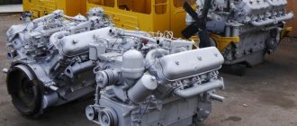
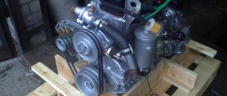
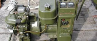
SMD-14, as can be seen in the photo, has several important differences from most analogues used in specialized vehicles. It is necessary to mention its compact dimensions, as well as its light weight, which greatly simplifies the maintenance and repair of the power unit.
A distinctive feature is quite powerful performance indicators, which can be adjusted if necessary, which is extremely important for the agricultural industry. Other important characteristics include:
- availability of a protection system;
- ease of maintenance of the fuel system;
- presence of a starting motor;
- 2 generator operating modes.
Such innovations, compared to previous models of the concern, allowed the SMD-14 to quickly replace outdated predecessors and become one of the most popular power units.
Engine Specifications
As mentioned earlier, the performance of the motor made it incredibly popular among manufacturers of agricultural machinery. A large number of spare parts, as well as the low cost of this type of device, make it a profitable and reliable solution, especially in comparison with numerous foreign analogues.
The most important operating parameters of the SMD-14 engine include:
- total power - 75 hp;
- rotation speed - 1800 rpm;
- fuel consumption level - 218g/kWh;
- number of cylinders - 4 pcs., diameter 120mm;
- piston stroke - 140mm.
The model’s performance, combined with a successful design and long service life of the unit, allows us to call it one of the most popular at the time of release.
Adjusting the ignition of YaMZ 238 - how to set
On all engines, without exception, early ignition is set. Adjusting the ignition of the YaMZ 238 is no exception. This is done so that at the moment of compression at top dead center the fuel is already ignited.
Compression at TDC causes a maximum increase in the pressure of already burning fuel, resulting in the highest engine efficiency and more complete combustion of the fuel. Ignition advance should occur 10-12 degrees of crankshaft rotation before the piston reaches top dead center at the moment of compression. Both 15 degrees and 18 are allowed, depending on the operating conditions of the engine.
Device SMD-14
The design of the motor is quite simple and allows for the possibility of changing its power, which is especially convenient when performing various tasks with its help. To do this, you will need to adjust the engine in accordance with the standard algorithm specified in the instructions for it. It is advisable to include the following structural elements among the main components of SMD-14:
- starting motor PU101-U;
- starter - SG352;
- a generator capable of operating with or without a battery;
- protective equipment - spark arrestors;
- lubrication system, including drain, bypass and safety valve;
- filter elements;
- cooling system.
The fuel system of the unit also deserves mention, which provides the ability to wash the filters without disassembling it, which makes maintenance simple and convenient. It should be mentioned that the design of the motor has been improved several times. This led to the emergence of new generations of SMD, as well as the 14NG modification, which is characterized by greater power and improved performance.
How to install the ignition on a SMD engine
The timeliness of fuel ignition, the completeness and efficiency of its combustion depend on the moment the injection into the combustion chamber begins. The engine running with knocking noises and smoking when the power decreases may be the result of incorrect setting of the start point of fuel supply.
Rice. 1. Checking the angle of start of fuel supply by the pump on the engine: 1 - main clutch oil seal cover; 2 — pointer arrow; 3 — main clutch brake pulley
Promotional offers based on your interests:
There are several methods for controlling the moment when fuel supply begins. The most common and convenient method for checking directly on the tractor is the meniscus method. To determine the moment when fuel begins to flow along the meniscus, a momentoscope is used - a glass tube with an internal diameter of 1-2 mm, connected by a rubber tube to a piece of high-pressure tube 50-60 mm long. The moment when the fuel pump starts supplying fuel is checked as follows. Remove the high pressure pipe of the first cylinder and install a momentoscope on the fitting of the first section of the pump. Loosen the nuts securing the clutch oil seal cover and the clutch brake shield and remove the shield, moving its top. Place the arrow under the top unscrewed nut with its tip facing the outer cylindrical surface of the brake pulley and secure it. Tighten all nuts securing the oil seal cover. Air is removed from the power system and the fuel supply control lever is set to the maximum supply position. Having turned on the decompression mechanism, rotate the engine crankshaft with the crank until fuel appears in the glass tube of the momentoscope. Remove some of the fuel from the tube by shaking it, slowly rotating the crankshaft clockwise, and observe the fuel level in the glass tube. At the moment the fuel level in the tube begins to rise, stop rotating the crankshaft and apply a mark with a pencil or chalk on the brake pulley. Then unscrew the mounting pin from the flywheel housing and insert it into the same hole with the extended end without threads until it stops against the flywheel. Turn the crankshaft until the set screw fits into the hole in the flywheel and make a second mark on the brake pulley. This position of the crankshaft corresponds to the position of the piston of the first cylinder in c. m.t. at the end of the compression stroke.
The moment of the start of fuel supply relative to c. m.t. is determined by the distance between the marks on the brake pulley. The arc length, equal to 50-55 mm, corresponds to the moment the fuel supply begins 27-30° before east. m.t. according to the angle of rotation of the crankshaft. One degree of crankshaft rotation corresponds to an arc length of 1.83 mm.
If the injection advance angle during checking does not correspond to the normal one (27-30°), it must be adjusted by moving the spigot flange relative to the fuel pump drive gear. To do this, remove the cover in front of the slip flange, unscrew the two bolts securing it, turn the flange to the required position and secure it with bolts. Then they check again the moment when the fuel supply starts and, if it corresponds to the required one, put the cover and brake flap in place.
Source
Maintenance and repair of the SMD-14 engine
The engine in question relatively rarely requires any specialized maintenance or repair, however, with improper operation, as well as irregular maintenance, you can encounter a number of serious problems. One of the most common is the unstable operation of the generator, which can be caused by a wide range of reasons:
- wear of cylinders, bearings, related elements;
- lack of tightness in the cooling system;
- clogged filters;
- changing the shape of the cylinders.
To eliminate the malfunction, it is necessary to study the condition of the above components and, if necessary, replace or clean them, which will return the generator to an operational state. Filters can be dismantled for washing without additional manipulations, which is an important advantage of the 14th SMD model.
Also worthy of mention is the adjustment of valves, which must be performed during each major overhaul of the power unit, as well as as problems arise in their operation. The adjustment procedure in this case is completely identical to the standard one characteristic of diesel engines.
How to install the ignition on a SMD engine
@Bogdan Burachok thank you
@leonid moma on the SMD 22 turbo engine, install a camshaft (22 05 01) with larger intake cams. In order to relieve more tension.
@Andrey Rehetnyk there will be an opportunity to look, please take a look, you often take them apart and assemble them, as I understand it, for turbo engines one is worth another for simple ones
Hello. I don't know the markings
If I have a SMD 22 block, a 14-n piston head with a small combustion chamber, what kind of combustion mark will be and how the marks will stand, so I will be even longer.
@Alexey Osadchikh 0671788496
Hello Andrey, I have exactly the same as you, block 22 head, 14-piston 20th, I took it apart but don’t dare to reassemble it, how did you solve this problem if it’s not a secret.
@Andriy Garasimlyuk 0976951202
Can I have a phone number?
You won’t be able to figure it out here without letters))))))
Hello, what kind of crankshaft do you have at the moment, I found it without weights with weights like yours, what kind of lutishe is it, diaque camshaft 22 necks 45 and 42mm piston 22 and why is it smoking
The camshaft is stuck dead while driving, the engine has stalled, how can I get it out?
Tell me, please, I have SMD 18 and the gear on the pump is set to the correct position.
17 18 t on n all other t on t
Hello! Please tell me how to set the ignition on the SMD-22 engine
Can you tell me how to remove the camshaft without turning the engine over? I broke both the front cover and the one behind the gears, but it cannot be removed until the camshaft is pulled out.
@Andrey Rehetnyk thanks, I'll try it
You need to use a magnet to lift the pusher stacks one by one
Andriy, why is the engine on the combine more efficient?
@Andrey Rehetnyk Hello! Yes, you can see the Dima train on the collection
Hello Anton. without realizing it, I have.
Hello! Please tell me how to center the casing or (flywheel housing) I would like to install an SMD 23 engine, what do you think and how to install the basket? Thank you
@Andrey Rehetnyk Andryukh tell me what to do with the tags? I've read too much now I can't give it a go
@aleksey osadchikh there is a 22 marking on the block and on the head, these engines were installed on combines with an intercooler, this combine is in the same hands from new
I re-read 1000 comments and realized that I didn’t understand anything, well, in general, I bought a Niva SK 5, with the engine stuck, took it apart, now I’m afraid to put it back together, changed the crankshaft, put everything on the mark k_k r_r t_t but I don’t dare close the lid, in general I couldn’t understand what kind of engine do I have, 18 or 22? with a turbine, with a booster, on the block the same as yours, CL 22, head 14N, piston 20E, I can’t imagine what to call it, help me figure it out.
@Andrey Rehetnyk hello Andrey, I have a question: how did you determine that you have an SMD 22 engine?
Sorry. but I didn't understand the essence of the question. )))))))
Exactly. I said it wrong when parked. thanks for correcting it. )))))))) yes turbocharged
During the educational program, if I’m not mistaken, the P-P marks on all engines should match, but the T-T or T-N marks are fuel advance marks (your engine block is upside down, but in the book it is drawn in its normal form).
Diesel hydraulic pumps SMD-18
To ensure the operation of hydraulic mechanisms that are used on the tractor or together with it, this diesel engine is equipped with two gear pumps: NSh5O-2-L (left rotation), which is used in the tractor’s hydraulic lifting system, and NSh1OE-3-L left rotation, which used in the hydraulic servo system to supply oil to the hydraulic booster for controlling the main clutch.
The hydraulic pump is attached to a drive mounted on the gear housing and is driven by a gear that is in constant mesh with the camshaft gear. The transmission of rotation to the hydraulic pump is carried out by a cam coupling, the fixed half of which is made integral with the drive shaft, and the other moves freely along the splined shaft of the pump drive gear.
When the gears rotate, the disengaged teeth create a vacuum, and oil is sucked from the reservoir into the pump housing. When filling the cavities between the teeth, the liquid is pumped into the discharge cavity. When engaged, the gear teeth force the oil into the discharge pipeline.
To reduce internal oil flows through the gaps between the end surfaces of the gears and bushings, the pump is equipped with automatic control of the size of the gaps at the ends of the gears. Oil from the pressure chamber enters the cavity above the bushings and tends to press bushings 13 and 15 towards the ends of the gears, while at the same time, oil also presses on the bushings from the side of the gears, but over a slightly smaller area, resulting in the force pressing the bushings to the ends of the gears. is small, and the bushings wear out slightly.
Diesel cooling system SMD-18
The cooling system removes heat from the hottest engine parts (liner, cylinder block, cylinder head) and maintains the necessary thermal regulation of the diesel engine.
Both antifreeze and ordinary water are used as a coolant.
The cooling system of the SMD-18 diesel engine is a closed forced one; fluid is circulated through it using a centrifugal water pump.
The cooling system consists of a radiator, a water pump with a fan, water cavities in the block and cylinder head connected to the starting engine cooling system.
To automatically regulate the temperature regime, a thermostat model TS-107 is installed on the diesel engine. The thermostat is located in an aluminum housing mounted on a water pipe and is connected to the upper radiator reservoir and water pump with hoses.
It is a one-piece structure, which consists of a brass body, a stand, and a holder, fastened together. This is how the thermostat works. When the coolant temperature rises above +80°C, the filler, heating up, expands in volume and puts pressure on the rubber insert 10, which in turn contracts and tends to push out the piston. As the coolant temperature continues to rise, the valve opens fully and flow passes through the radiator.
The coolant is poured through the radiator neck and fills the entire cooling system of the diesel engine and the starting motor.
When a diesel engine is running, coolant from the lower radiator tank goes through a pipe to the water pump, and it pumps it into the water distribution channel of the crankcase. From the water distribution channel, the coolant enters through the windows into the space between the walls of the block and the liners (water jacket), and, washing the liners, cools them.
From the crankcase, through the water supply channels, it rises into the water jacket of the cylinder head, from there, through the drainage pipe through the thermostat (if the valve is open), it enters the upper radiator tank. Flowing through the tubes of the radiator core, the liquid is cooled by the air flow, which is pumped by the fan.
The water pump is combined with the fan using a common drive and is located at the front end of the cylinder block.