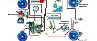
Category: KAMAZ
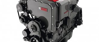
- Description of KamAZ cylinders
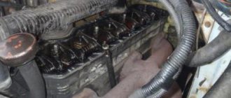
- Internal processes
- Kamaz cylinder arrangement
- Adjusting Kamaz valves
- Preparing the vehicle Fixing the main chamber piston at the top
- Setting gaps
- Setting up KamAZ 740, 6520, 5511 valves and other modifications:
The correct approach to making non-standard decisions made the motors reliable, and the use of a number of technical techniques by the inventors made them recognizable. These characteristics include the operating order of KamAZ cylinders.
At first glance, the indicator is not significant. However, a detailed study of the issue brings clarity and understanding that the design of the installation is based on the order of operation of the KamAZ engine cylinders. Let's look at the characteristics in detail.
KamAZ 44108:
Description of KamAZ cylinders
The sequential alternation of strokes in the engine chambers represents the order of operation of the KamAZ 740 cylinders and other modifications. When calculating this indicator, attention is paid to the characteristics inherent in the block, as well as the design features of the part that converts the force from the connecting rods into torque and the part that controls the opening and closing of the intake and exhaust valves.
KamAZ block:
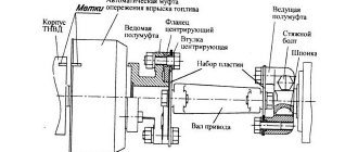
Thus, the KamAZ power unit has a V-shaped block layout. A design feature of the frame, a shift of the left row of pistons relative to the right by 29.5 millimeters. This arrangement is due to the fastening of two connecting rods on one neck, the action of the parts is directed in opposite directions. Thus, the order of operation of KamAZ cylinders follows the scheme 1x5x4x2x6x3x7x8.
The design of the crankshaft simplifies the product technologically, and at the same time increases the efficiency of the power plant. The shaft is shortened, designed for eight pistons, which are attached to cranks mounted on 4 journals. The coherence of the gas distribution mechanism, valves and cranks increases the potential of the engine.
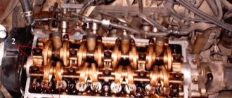
Device
The design of this motor model includes the following elements:
- timing;
- power supply, lubrication and cooling system;
- injection pump;
- nozzles;
- oil pump;
- fluid coupling
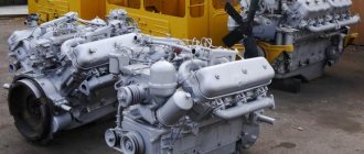
Engine
The KamAZ-740 engine has the following cylinder operating order: 1,5,4,2,6,3,7,8. The direction of rotation of the crankshaft is the right side.
Crankshaft size table for this engine model:
| 1H | P1 | P2 | P3 | P4 | |
| Indigenous necks | 95,0-0,015 | 94,5 | 94,0 | 93,5 | 93 |
| Crankpins | 80,0-0,013 | 79,5 | 79 | 78,5 | 78,0 |
The torque is transferred to the main components using spur gears. These gears operate the drives of the system, which is responsible for gas distribution, pumps, compressors and hydraulic boosters.
The motor is able to withstand operation even in low temperatures. Operating range: +35…+40°С.
The design of the mechanism responsible for gas distribution inside the engine includes such elements as:
- camshaft equipped with gears;
- pushers that have guides;
- barbell;
- rocker arm equipped with adjusting screws;
- locknuts;
- intake and exhaust valves on which springs are installed;
- fastening;
- camshaft drive;
- bearing bushing;
- washer;
- spring plate.
The gas distribution mechanism is made entirely of reliable steel alloy. The timing belt has 5 bearing-type journals and 16 cams.
Kamaz cylinder arrangement
A correct understanding of the operating principle of the power plant depends on the numbering of the KamAZ cylinders. This procedure is approved by European regulations. According to the agreements, the manufacturer is obliged to mark the cameras of manufactured products, starting with the right front one. Knowing where the first cylinder is located on a KamAZ, it is called the main one, and the valves are adjusted.
KamAZ 740 cylinder arrangement diagram:
The nozzles that supply the mixture charge into the chamber volume are marked in pairs with the cylinder being serviced. The main sprayer is attached to the main cylinder. The KamAZ 740 is marked in the following order: right line of cameras - from the first to the fourth; left line of cameras – from the fifth to the eighth. The rows are counted from the front of the machine. This information will be useful when setting up the engine if the fuel pump is replaced. Adjusting the injection of the working mixture into the chamber without this information is impossible. In addition, the indicator affects the setting of the gas distribution mechanism.
Internal processes
The functioning of the KamAZ installation is associated with the processes occurring in the chamber. Actions occur in a certain strict sequence with periodic repetition in each cylinder. The sum of processes is a work cycle consisting of periods of gas distribution.
During one sequence of working processes, one ignition of fuel is performed in the cylinder. The delay period, from one flash to the next, affects the smooth running of the power unit. The smaller the gap, the less vibration when the motor operates. Smoothness also depends on how many cylinders there are in the KamAZ. In our version we are talking about eight cameras. This is a reasonable number, since a large number of cameras leads to a longer interval between flashes and harsh operation of the motor. At the same time, an insufficient number of cameras does not provide the necessary power.
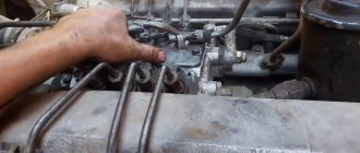
Preparing the car
The machine being manipulated is placed on a flat surface. The driver's cabin reclines and locks. The upper part of the gas distribution mechanism is dismantled and the pump is turned off.
KamAZ 43118:
Devices:
- Keys: open-end for 13, ring for 14;
- Screwdrivers;
- Steel rod;
- Set of measuring plates.
Fixing the main chamber piston at the top
- Check the fixation force of the camera heads;
- Move the flywheel stop device down;
- Remove the flywheel housing protection plate;
- Insert the steel rod into the hole in the flywheel, turn clockwise until the product stops. Position – beginning of mixture injection (cylinder one).
Flywheel retainer, KamAZ engine:
Setting gaps
- Rotate the flywheel (2 holes - 60°, each 30°);
- Adjust the spacing of the first pair of cameras (1st and 5th). Using a 14 ring wrench, loosen the nuts
- adjusting screws. Use the 0.3 plate to adjust the intake valve, and the 0.4 plate to adjust the exhaust valve.
- Fix the nut, force 33-41 Nm.
- Adjust the spacing in chambers one through eight.
Setting up KamAZ 740, 6520, 5511 valves and other modifications:
- 180 degrees – 4th, 2nd;
- 180 degrees – 6th, 3rd;
- 180 degrees – 7th, 8th.
Adjusting clearances KamAZ:
Specifications
KamAZ-740 engine - technical characteristics:
| View | Four stroke |
| Number of cylinders | 8 |
| Camber angle | 90° |
| Cylinder diameter, cm | 12 |
| Stroke of the piston part, cm | 12 |
| Engine displacement, l | 11 |
| Compression level | 17 |
| Motor power | 210 l. With. |
| Maximum torque, Nm | 650 |
| Engine weighs, kg | 750 |
| Weight of box with starter, kg | 760 |
| Number of valves | 2 on each cylinder |
| Parameters, m | 1*0,9*0,95 |
| Power supply system | injection pump |
Additional characteristics of the KamAZ-740 engine:
- Ignition occurs due to compression.
- The cooling system is liquid.
Degree position of exhaust and intake valves in different valve timing phases:
- open - 13 and 66°;
- closed - 49 and 10°.
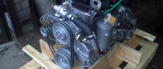
Engine
ENGINE KAMAZ vehicles are equipped with engines of the KAMAZ-740.10 models; KAMAZ-7403.10 or KamAZ-740.11-240. Features of the design, maintenance and repair of KAMAZ-740.10 and KAMAZ-7403.10 engines are set out in this manual. Features of the design, maintenance and repair of KAMAZ-740.11-240 engines are set out in the operating manual 740.11-3902006. Rice. 1. Longitudinal section of the KamAZ-740.10 engine: 1 – generator; 2 – low pressure fuel pump; 3 – manual fuel priming pump; 4 – high pressure fuel pump; 5 – automatic fuel injection advance clutch; 6-half coupling driving the high pressure fuel pump; 7-connecting pipe for inlet air ducts; 8 – fine fuel filter; 9 – cam shaft; 10 - flywheel; 11 – flywheel housing; 12-drain plug; 13-engine crankcase; 14-crankshaft; 15 – oil pump; 16 – drive shaft of the leading part of the fluid coupling; 17 – generator drive pulley; 18-fan impeller Fig. 2. Cross section of the KamAZ-740.10 engine: 1 – full-flow oil purification filter; 2 – oil filler neck; 3 - oil level indicator; 4 – centrifugal oil filter; 5 - thermostat box; 6 – front eye bolt; 7 – compressor; 8 - power steering pump; 9 – rear eye bolt; 10 – left water pipe; 11 – torch candle; 12- left intake air duct; 13 – nozzle; 14 – nozzle mounting bracket; 15 – exhaust manifold pipe; 16 – exhaust manifold Fig. 3. KamAZ-7403.10 engine with turbocharging: 1 – exhaust manifold; 2 – starter; 3 – cylinder head cover; 4 – oil sump; 5 - gear shift lever bracket; 6 – water pump; 7 – fan impeller; 5 – drive belts; 9 - centrifugal oil filter; 10 - generator; 11, 25 – brackets; 12-gear shift lever; 13 - connecting pipe; 14 – high pressure fuel pump regulator cover; 15, 22 – torch candles; 16 – solenoid valve; 17, 23 – intake manifolds; 18 - fine fuel filter; 19 - compressor; 20.26 – turbochargers; 21 – power steering pump reservoir; 24 – pipe
The KAMAZ-740.10 and KAMAZ-7403.10 engines have the following design features: — pistons cast from a high-silicon aluminum alloy, with a cast-iron reinforcing insert under the upper compression ring and a colloidal-graphite running-in coating for the skirt; — cylinder liners, volumetrically hardened and treated with flat-top honing; —piston rings with chrome and molybdenum coating of the side surfaces; — three-layer thin-walled steel-bronze liners for main and connecting rod bearings; — a closed cooling system filled with low-freezing coolant, with automatic temperature control, a fluid coupling for the fan drive and thermostats; —highly efficient filtration of oil, fuel and air using paper filter elements; — an electric torch air heating device that ensures reliable engine starting at negative ambient temperatures down to minus 25 C.
Rice. 4. Numbering scheme and operating order of cylinders: 1. 8 – cylinders; I – right row; II – left row
CYLINDER BLOCK AND UNIT DRIVE The cylinder block is cast from alloy gray cast iron integral with the upper part of the crankcase. The crankcase part of the block is connected to the main bearing covers with transverse tie bolts, which gives strength to the structure. To increase longitudinal rigidity, the outer walls of the block are made curved. The bosses of the cylinder head bolts are bosses on the transverse walls that form the water jacket of the block.
The left row of cylinders is shifted forward relative to the right by 29.5 mm, which is caused by the installation of two connecting rods on one crank pin of the crankshaft.
A cover is attached to the front of the block that covers the hydraulic coupling of the fan drive, and at the back there is a flywheel housing, which serves as a cover for the accessory drive mechanism located at the rear end of the block. Wet-type cylinder liners are easily removable, made of special cast iron, volumetrically hardened to increase wear resistance. The liner mirror is processed by flat-top honing to obtain a grid of depressions and areas at an angle to the liner axis. This treatment helps retain oil in the depressions and improve the running-in of the liner. In the connection between the liner and the cylinder block, the water cavity is sealed with rubber O-rings. In the upper part there is a ring installed under the collar in the bore of the liner, in the lower part two rings are installed in the bores of the block.
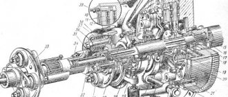
Rice. 5. Generator drive gear: 1 – M12x1.25x90 bolt for fastening the roller bearing; 2, 21 – intermediate gears; 3-bolt; 4 – spring washer; 5-cuff; 6-rear bearing housing; 7-gasket; 8 – cracker; 9 – high pressure fuel pump drive gear shaft; 10, 20 – keys; 11, 15 – ball bearings; 12 – drive gear of the high pressure fuel pump; 13-camshaft assembly with gear; 14 - thrust washer; 16 – drive gear axis; 17 – washer; 18 – bolt MIOxl, 25×25; 19 – double-row tapered roller bearing; 22 – thrust ring; 23 – retaining ring; 24 – crankshaft drive gear
The drive of the units (Fig. 5) is gear-type with spur gears, the gas distribution mechanism is driven from the drive gear 24, mounted with interference on the crankshaft shank, through a block of intermediate gears 2 and 21. The block of intermediate gears rotates on a double tapered roller bearing 19. Camshaft gear shaft 13 is installed on the shaft shank with interference. When assembling, you must ensure that the marks on the end of the gears in mesh are aligned. The high pressure fuel pump is driven by gear 12, which is meshed with the camshaft gear. Rotation to the high-pressure fuel pump is transmitted through the driving and driven coupling halves with elastic plates that compensate for misalignment.
The compressor drive gear and the power steering pump drive gear are engaged with gear 12 of the fuel pump drive. The tightening torques for bolts 18 securing the axis of the intermediate gears are 49.1. 60.8 Nm (5.6.2 kgf.m), bolt 1 for securing the roller bearing 88.3. 98.1 Nm (9.10 kgf.m).
History of creation[edit | edit code]
The prototype of the future KamAZ-5320 was developed at ZIL and was called ZIL-170. The first ZIL-170 was built in 1968. It had an engine from the Yaroslavl Motor Plant (YaMZ). Already in May 1969, the first prototype of the ZIL-170 vehicle passed its first tests on the Uglich-Rybinsk section. But after the adoption of the resolution of the Central Committee of the CPSU and the Council of Ministers of the USSR “on the construction of a complex of factories for the production of heavy-duty vehicles in Naberezhnye Chelny,” it was decided to transfer further development and subsequent assembly of the ZIL-170 to KamAZ. At the same time, the name of the car was changed to KamAZ-5320. The first experimental KamAZ-5320 rolled off the assembly line in 1974.
The first serial KamAZ trucks rolled off the assembly line on February 16, 1976. According to the tradition of those years, the trucks from the first batch were decorated with the slogan “Our gift to the XXV Congress of the CPSU.”
Based on the KamAZ-5320, the KamAZ-5410 truck tractor, the KamAZ-5511 dump truck, the KamAZ-53212 extended flatbed truck, the KamAZ-53213 chassis, as well as a family of two-axle analogues (the extended KamAZ-5325 and the basic KamAZ-4325 flatbed, the KamAZ-43255 dump truck) were created , truck tractor KamAZ-4410). Production of the first two models of the 5320 family began in 1977, the rest - later. All models of this family had a similar design and were largely unified.
Maintenance and repair
The repair manual describes how you can independently eliminate some engine malfunctions, as well as the frequency of maintenance.
Before the warranty card expires, it is not recommended to disassemble the motor yourself, otherwise the possibility of repair under warranty will disappear.
During the period of continuous operation it is necessary:
- Carry out daily maintenance, i.e. check the oil level and contamination.
- Carry out maintenance 1 after 5000 km of vehicle mileage.
- Carry out maintenance 2 after 14,800 km.
- Carry out preparatory work before operation in winter and summer.
Technological map of disassembly
For disassembly, it is recommended to use the P-770 rotary stand.
Technological map for disassembling the 740 motor:
- Remove the housing cover and disconnect the positive and negative terminals of the battery.
- Raise the cabin trim and remove the buffer.
- Tilt the cab 60°.
- Disconnect the wires and plug from the generator.
- Disconnect all sensors.
- Remove the air duct.
- Unscrew the bolts of the fan impeller and remove it.
- Disconnect the fuel supply and drain lines.
- Clean the cooling system of excess fluid.
- Drain the oil fluid from the engine crankcase.
Engine repair
The price for a major overhaul of a KamAZ-740 engine starts at 40 thousand rubles.
Possible malfunctions and ways to eliminate them:
- The motor does not start. This may be due to the presence of air in the power system. It is necessary to eliminate the leak and bleed the system.
- The motor is not running at full power. It is necessary to replace the filter cleaning elements, wash the coarse filter, and tighten the nuts in the fuel pipes.
- Extraneous noise during operation. You should check the turbine housing mounting bolts, inspect the engine for interference with the rotor part in the extreme position, and send the turbocharger for maintenance.
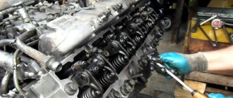
How to adjust valves
In order to adjust the valves, it is necessary to place the vehicle on an inspection ditch or a flat surface.
The procedure for adjusting valves on a KamAZ engine:
- Remove the cover from the cylinder and check the tightness of the mounting bolts.
- Set the locking handwheel to the lower position.
- Remove the timing hatch cover and set it to the position where the spring engages the flywheel.
- Check the tightness of the nuts on the cylinder rocker arm.
- Rotate the crankshaft 60° from the second hole in the flywheel.
- In order, adjust the valves 180° in two steps: first and fifth, fourth and second, sixth and third, seventh and eighth.
Repair and adjustment of fuel injection pump
In order to repair the KamAZ-740 fuel injection pump, it is necessary to disassemble the pump:
- Remove the plugs.
- Unscrew the ring nut and compress the coupling.
- Remove the seal and remove the protective covers.
- Remove the nuts from the rear cover spring washers.
- Remove the retaining ring and cam shaft.
Repairing the engine power system may involve adjusting the injectors:
- Place the part on the stand.
- Check the pressure level when starting to raise the needle. If necessary, make adjustments.
- Change the overall thickness of the adjusting washers that are installed under the spring.
- Reinstall the injector and check the pressure level.
How to set the ignition
In order to set the ignition, it is necessary to correctly calculate the angle, otherwise the engine will not work correctly.
Ignition installation procedure:
- Place a mark on the injection pump.
- Turn the motor until the mark coincides with the mark.
- Bring the piston into a fixed position using the locking element.
- Determine in what position the compression process begins in the cylindrical part of the mechanism.
- Lower the stopper until the stop piece fits into the hole. The flywheel must be rotated using a special lever.
- Loosen the pump drive mounting bolts and align the mark with the outer part of the index piece.
What kind of oil to pour
It is recommended to fill the 740 engine with the following brands of oil: KAMAZ SAE 15W40 API CI-4/SL K10-40.50, Lukoil-Super (SAE 15W-40, CE/SG).
In order to decide which oil to pour, you need to know under what conditions the vehicle will be operated. The volume of oil in the engine should not exceed 35 liters.
Guide to changing oil in the KamAZ-740 engine:
- Warm up the engine.
- Drain off any remaining oil.
- Flush the system, crankcase pan, oil intake and ventilation breather.
- Fill with new oil fluid to the maximum mark.
- Check the oil pressure level.
Tools required for valve adjustment
Here, I will describe the standard method of adjusting valves on the YaMZ-238 engine. To perform this operation, you will need the following tool
:
- A 30mm wrench (preferably a socket wrench) with the ability to put a pipe amplifier on it;
- Wide slot screwdrivers;
- Socket wrench 17;
- 0.25 mm feeler gauge.
It is also desirable to have a groove for turning the crankshaft. However, if it is not available, then it is quite possible to do without it, although it will be somewhat inconvenient.