D-245 engines are powerful 4-stroke units with 4 cylinders arranged in a row. The unit is equipped with a direct injection system. This ensures an increased level of fuel combustion and, accordingly, increases engine performance.
However, this engine, like any other equipment, is subject to periodic breakdowns. In order for the unit to work correctly, its valves must be adjusted in a timely manner. With some theoretical training, this procedure can be carried out independently.
Engine D-245: valve adjustment. D-245: description
Diesel power units D-245, the valve adjustment of which we will consider below, are four-stroke piston engines with four cylinders. Internal combustion engines of this type have in-line vertical cylinder placement, are equipped with direct fuel injection and combustion of the fuel mixture as a result of compression. Additionally, the parameters of the unit are improved by turbine charging with intermediate cooling of the incoming air. Let's consider the characteristics of the engine, as well as the possibility of adjusting the valves.
D-245: general information
The use of a turbine compressor with adjustable air flow makes it possible to create optimal throttle response in the engine. This indicator is ensured by an increased torque parameter with minimal crankshaft speed. At the same time, the exhaust gases meet the required standards.
All motors in this series are designed for normal operation in temperature conditions from -45 to +40 degrees Celsius. The main scope of application of the diesel engines under consideration is power plants for road, construction equipment and wheeled tractors.
Setting TDC at the moment of compression
The problem arises when the piston becomes in the correct position to adjust the valves of the first cylinder. The piston must be at TDC during the compression stroke. There is a mark on the crankshaft pulley. It needs to be aligned with the TDC designation on the scale.
Indeed, the piston of the first cylinder will rise to TDC. But it is necessary to make sure that it is in the compression stroke. Because for the full cycle of engine operation from the first to the eighth cylinder. The piston becomes twice at TDC. We are only interested in one of its positions. This position can be determined in several ways.
- If the engine is in working order on the car. You can remove the tip from the spark plug wire going to the first cylinder. And turn the crankshaft with the ignition on. At the moment a spark jumps between the wire and ground. You should place a mark on the pulley with the TDC designation on the scale. The spark will jump before the piston reaches top dead center. And by setting the marks, the piston will move to the desired position.
- You can unscrew the spark plug of the first cylinder and plug the spark plug hole with a paper plug. When cranking the crankshaft, the plug will shoot out. All that remains is to align the mark on the pulley with the TDC mark on the scale. You can simply plug the hole with your finger. When air starts to come out from under it, all you have to do is align the marks. This indicates that compression is forming in the cylinder. Compression begins. Therefore the valves are completely closed.
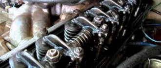
- Visually, the TDC position is determined by the rocker arms. In the compression position when the piston approaches TDC, the rocker arms are not movable. The valves are closed. In the second position, when the piston approaches TDC, one valve closes. The second one, after passing TDC, begins to open immediately. If the valves are stationary, all that remains is to align the marks.
After the piston of the first cylinder is in the correct position, it is necessary to adjust the valves of the first cylinder.
Characteristics
Before studying the valve adjustment on the D-245 engine, let’s consider its technical parameters:
- Manufacturer: MMZ (Minsk).
- Type - four-stroke in-line diesel engine with an in-line arrangement of 4 cylinders.
- The fuel mixture is supplied by direct injection.
- Compression – 15.1.
- Piston displacement – 125 mm.
- The cylinder diameter is 110 mm.
- Working volume – 4.75 l.
- Cooling is a liquid system.
- Speed – 2200 rotations per minute.
- Average fuel consumption is 236 g/kWh.
- Power indicator – 77 kW.
- Camshaft gear.
- Intermediate gear.
- Crankshaft toothed element.
- TN drive wheel.
Modifications
The procedure for adjusting the D-245 valves is identical for all modifications of this series. Among them:
- D-245-06. This engine has a power rating of 105 horsepower, four cylinders, in-line arrangement, liquid cooling and free atmospheric intake. The model is installed on MTZ 100/102 tractors. As standard, the engine is equipped with an ST-142N starter, a G-9635 generator, as well as a pneumatic compressor, a gear-type pump, an oil pump and a paired disc clutch.
- D-245. 9-336. This diesel power plant has an in-line arrangement of four cylinders and turbine supercharging. The motor is installed on MAZ-4370 vehicles, equipped with a 24-volt starter 7402.3708, a compressor with a TKR 6.1=03-05 turbine, fuel, water, oil and gear pumps. The clutch is a single-plate clutch without a housing.
- D-245. 12C-231. The modification has a power of 108 “horses”, in-line cylinder arrangement, turbocharging. Diesel is mounted on ZIL 130/131. The engine is equipped with a PP4V101F-3486 fuel pump, a turbine and pneumatic compressor, and a single-plate clutch with a crankcase.
The timing belt assembly also includes various fasteners, washers, nuts, rocker arms, pushers, camshafts, crackers, and disc retainers.
Advantages
The main advantage of the D-245 is its simplicity and reliability during long-term operation. At the same time, the power plant satisfies all the needs of users, because for many of them it is very important to purchase not only an engine with a long service life, but also with the necessary power parameters.
Engine D-245
DIESEL TRACTORS MTZ-100, MTZ-102
GENERAL DEVICE OF DIESEL D-245 AND D-245L
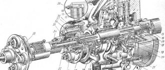
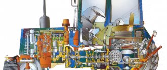
The MTZ-100 and MTZ-102 tractors are equipped with a four-cylinder in-line four-stroke diesel engine D-245 with direct fuel injection, liquid cooling and turbocharging. Its rated power is 77.2 kW (105 hp) at a crankshaft speed of 2200 rpm. The general view of D-245 is shown in Figures 1 and 2, and D-245L is shown in Figures 3 and 4, their longitudinal and transverse sections are shown in Figures 4 and 7-
The difference between the D-245 and D-245L is the starting system: in the first, from an electric starter, in the second, from a starting carburetor engine.
Diesel D-245 was created on the basis of D-240. An increase in its rated power to 77.2 kW was achieved through the use of turbocharging.
The level of unification with the D-240 diesel engine is more than 74%, and taking into account the use of parts on the D-240 diesel engine from the D-245 diesel engine (reverse unification), its value increases to 86.4%.
In connection with the installation of the TKR-7S-4 turbocharger, such parts of the D-240 diesel engine as the exhaust pipe, exhaust manifold, air filter, etc. were completely changed. To ensure high operational reliability, the piston, crankshaft, set of piston rings, main and connecting rod bearings were modernized , cylinder block and head, valve drive mechanism, fuel pump and filter, water pump drive, etc. A generator with a power of 0.7 kW (instead of 0.4 kW) was used, which ensured the balance of electricity on the tractor.
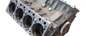
A diesel engine consists of a cylinder block, a crank mechanism, a gas distribution mechanism, a lubrication system, systems: fuel and air supply, cooling, starting, electrical equipment and turbocharging.
The cylinder block of the D-245 diesel engine has nozzles that supply oil to the bottom of the pistons to ensure their optimal temperature conditions, additional channels for removing gases from the crankcase to the breather, changes have been introduced into the design of the block related to the removal of oil from the turbocharger. Higher quality material was used for the crankshaft and connecting rods. The main and connecting rod bearings are three-layer, made of AO-6 alloy with a running-in coating.
The fastening of the flywheel to the crankshaft has been strengthened with seven bolts instead of six on the D-240 diesel engine. The crankshaft flange has a bore to install one of the clutch shaft supports. The cylinder head is equipped with insertable valve seats (Fig. 5), made of a wear-resistant alloy. The rocker arm shaft supports are installed on two supports with an additional fastening bolt, the lubricant supply to the valve rocker arms has been changed, and the intake and exhaust valves have been sealed. A modernized four-section high-pressure pump type 4UTNM with an anti-smoke pneumatic corrector, as well as an easily removable fine fuel filter element, are used.
Power, torque and fuel consumption vary depending on atmospheric conditions, which are characterized by temperature, humidity, barometric air pressure. Normal operating conditions are considered to be: ambient temperature plus 20°C, barometric pressure 101.3 kPa (760 mm Hg), relative air humidity 50%, fuel density at ambient temperature plus 20°C - 0.83 t/ m3, and its temperature is plus 20°C.
Rice. I. Diesel D-245 (left view);
Rice. 2. Diesel D-245 (fork on the right): 1 — oil dipstick; 2 — oil filler neck; 3 - clamp; 4 — filter with fuel purification pipe; 5 — exhaust manifold; 6 — turbocharger; 7 — thermostat housing; 8 — centrifugal oil filter; 9 - generator.
Rice. 4. Diesel D-245L (longitudinal section): 1 — oil sump; 2 - oil pump; 3 — crankshaft pulley; 4 — fan belt; 5 — timing gear cover; b - fan; 7 - water pump; 8 — thermostat housing; 9 — piston pin; 10 — connecting rod; 11 - piston; 12— cylinder liner; 13 — cap; 14 — cylinder head cover; 15 — cylinder head; 16 — cylinder head gasket; 17— cylinder block; 18 — back sheet; 19— flywheel; 20— counterweight; 21 - crankshaft; 22 — oil receiver; 23 — piston cooling nozzle; 24 — main bearings; 25 — connecting rod bearings; 26 — cavity in the connecting rod cheek; 27 — distribution gear; 28 — pump drive gear; 29 — flywheel ring gear; 30 — connecting rod bushing; 31 — flywheel mounting bolt.
Valve adjustment D-245
Before you begin setting up the valves, you need to study the structure and features of this unit. The camshaft has five bearings and is driven by the crankshaft and timing gear. Five bushings are used as bearings, which are placed in the block bores using the pressing method.
The front bushing is made of aluminum, is located in the fan area, equipped with a thrust collar that secures the camshaft from axial shifts, the other bushings are made of cast iron. Steel valve tappets are coated with special cast iron, the spherical surface has a radius of 750 mm. The camshaft cams are slightly inclined.
To correctly adjust the D-245 (“Euro-2”) valves, it is necessary to take into account that the pusher rods are made of steel rod and have a spherical part that fits inside the pusher. The valve rocker arms are made of steel and swing on an axis fixed by 4 stands. The axis of these elements is hollow, equipped with eight radial holes that serve to deliver oil; the movement of the rocker arms is stopped by spacers in the form of springs.
Timing belt and valves of diesel D-245
Timing distribution mechanism D-245 for ZIL-5301 Bychok, GAZ-3309, MAZ-4370 gear The gear consists of a camshaft, intake and exhaust valves, as well as parts for their installation and drive: pushers, rods, rocker arms, adjusting screws with nuts, plates with crackers, springs, struts and rocker axles.
The camshaft is a five-bearing one, driven by the crankshaft through distribution gears. The camshaft bearings are five bushings pressed into the block bores.
The front bushing (from the fan side) is made of aluminum alloy and has a thrust collar that holds the D-245 camshaft from axial movement; the remaining bushings are made of special cast iron.
Valve pushers are steel. The working surface of the pusher plate is overlaid with bleached cast iron and has a spherical surface of large radius (750 mm). As a result of the fact that the camshaft cams are made with a slight inclination, the tappets perform a rotational movement during operation.
The push rods are made of steel rod. The spherical part that goes inside the pusher and the rod cup are hardened. The valve rocker arms are made of steel and swing on an axis mounted on four racks. The outer pillars are of increased rigidity.
The rocker arm axis is hollow and has eight radial holes for supplying oil to the rocker arms. The movement of the rocker arms along the axis is limited by spacer springs.
Inlet and exhaust valves D-245 are made of heat-resistant steel. They move in guide bushings pressed into the cylinder head. Each valve closes under the action of two springs: external and internal, which act on the valve through a plate and crackers.
Sealing collars installed on the valve guides prevent oil from entering the diesel cylinders and exhaust manifold through the gaps between the valve stems and the guides.
The coordinated operation of the high-pressure fuel pump and the gas distribution mechanism is ensured by installing the timing gears according to the marks in accordance with Figure 1.
Rice. 1 — Diagram of installation of timing gears of the D-245 engine
1 - camshaft gear; 2 - intermediate gear; 3 - crankshaft gear; 4 – fuel pump drive gear.
Basic instructions for grinding in diesel valves D-245
Unscrew the nuts securing the rocker arm axle stands and remove the rocker arm axle with springs and rocker arms. Unscrew the head mounting bolts and remove the head. Dry the valve, remove the valve spring plate, valve spring, valve spring washers; Remove the sealing collar from the valve guide bushing.
Grind valves on special machines or on stands. Apply a paste prepared from a special composition to the chamfers of the valves or to the chamfers of the cylinder head sockets. The composition is diluted in diesel oil to a creamy state. To improve quality, it is recommended to add oleic or stearic fatty acid.
Continue grinding in valves D-245 of ZIL-5301 Bychok, GAZ-3309, MAZ-4370 Serration until a continuous matte belt with a width of at least 1.5 mm appears on the valve chamfer and on the valve seat chamfer, strip breaks or the presence of Risks are not allowed. The difference in the width of the belt is allowed to be no more than 0.5 mm.
After grinding in, it is recommended to wash the valves and engine block head. When assembling the head, lubricate the valve stem with engine oil. It is possible to grind valves manually, using a mechanic's tool, but the labor intensity of the grinding operation increases significantly.
Checking the tightening of the bolts securing the cylinder head of the D-245 diesel engine
Check the tightness of the bolts securing the D-245 cylinder head at the end of the run-in and every 40 thousand km on a warm diesel engine in the following order:
— remove the cap and cylinder head cover; — remove the rocker arm axle with rocker arms and struts; — using a torque wrench, check the tightness of all cylinder head mounting bolts in the sequence shown in Figure 2 and, if necessary, tighten them. Tightening torque - 220±10 Nm.
After checking the tightness of the cylinder head bolts, reinstall the rocker arm shaft and adjust the clearance between the valves and rocker arms.
Fig. 2 — Diagram of the sequence of tightening the cylinder head bolts
Checking the gap between valves and rocker arms of the D-245 engine
Check the gaps between the valves and rocker arms of the D-245 engine and, if necessary, adjust every 20 thousand km, as well as after removing the cylinder head, tightening the cylinder head bolts and when valve knocking occurs.
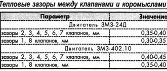
The gap between the rocker arm striker and the end of the valve stem when checking on an unheated diesel engine (water and oil temperature no more than 60 ºС) should be:
— intake valves — 0.25 mm; — exhaust valves — 0.45 mm.
When adjusting the gap between the end of the valve stem and the rocker arm on a cold diesel engine, set:
intake valves - 0.25 mm; exhaust valves - 0.45 mm
Adjust the gap between the rocker arm and the D-245 valve in the following sequence:
— remove the cylinder head cover cap and check the fastening of the rocker arm axle struts;
- turn the crankshaft until the valves in the first cylinder overlap (the intake valve of the first cylinder begins to open, and the exhaust valve begins to close) and adjust the clearances in the fourth, sixth, seventh and eighth valves (counting from the fan), then turn the crankshaft one revolution, installing overlap in the fourth cylinder, and adjust the clearances in the first, second, third and fifth valves.
To adjust the valve clearance, loosen the lock nut of the screw on the rocker arm of the adjustable valve and, turning the screw, set the required clearance using the feeler gauge between the rocker arm striker and the end of the valve stem. After setting the gap, tighten the lock nut. After adjusting the valve clearance, replace the cylinder head cover cap.
Peculiarities
The inlet and outlet valves D-245, the adjustment of which we will consider further, are made of heat-resistant steel. They are located in guide bushings, which are pressed into the cylinder head. A pair of springs acts on each element, ensuring its closure using plates and crackers. Oil getting into the cylinders is prevented thanks to the sealing collars that are located on the valve guides. The design also protects the exhaust manifold from flooding, preventing oil from passing through the gaps of the valve stems and guide bushings.
Lapping
Adjustment of valves D-245 (“Euro-3”) is carried out according to the following scheme:
- The nuts securing the rocker arm axle stands are unscrewed, and the axle itself is removed along with the springs and rocker arms.
- The head mount is unscrewed, after which it is dismantled. The valve should be dried out, its plate, springs and washers should be removed, and the seal should be removed from the guide sleeve.
- Adjustment of D-245 valves (grinding) is carried out on special machines or stands. A lapping paste with the addition of stearic fatty acid is applied to the chamfers of the elements.
- The grinding of parts should continue until a continuous matte edge with a width of at least 1.5 mm is formed on the chamfers of the valve and its seat. In this case, breaking of the belts is not allowed. Deviation in width in different areas is no more than 0.5 mm.
- After adjustment, it is recommended to rinse the cylinder head and valves, and then lubricate the working rod with engine oil. Alternatively, lapping can be done manually using bench tools. However, adjustment time and labor intensity increase significantly.
Checking and adjusting gaps
It is advisable to check and adjust the valves of the D-245 (Euro-2) engine in terms of clearances every 20 thousand kilometers. This procedure is also carried out after removing the cylinder head, tightening the cylinder head fixing bolts, or when a knock occurs in the valve compartment. The size of the gaps between the rocker arm and the end part of the valve stem on a cold diesel engine should be 0.25 mm on the intake valve and 0.45 mm on the exhaust valve.
To adjust the clearances, it is necessary to loosen the screw lock nut of the rocker arm of the valve being adjusted. Then, by turning the screw, the required value is set, which is measured using a probe between the striker and the end of the rod. At the end of the process, tighten the locknut and replace the cylinder head cover cap. The tightening of the mounting bolts is checked after running-in and every 40 thousand kilometers on a warm power unit. After checking, it is necessary to adjust the gap between the rocker arm and the valve, and then tighten the clamps.
Adjustment procedure
By adjustment we mean ensuring a regulated gap between the plane of the rocker arm striker and the end of the air intake and exhaust gas exhaust valves into the exhaust manifold. The setting sequence and parameters depend on the modification of the power unit and the method of supplying air to the combustion chamber. Additionally, the tightness of the nuts securing the head to the cylinder block is checked, which reduces the likelihood of gasket breakdown and warping of the part due to uneven thermal deformations.
Preparing for adjustment
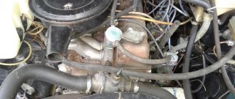
In preparation for tuning, you need to remove the sidewalls and fold back the hood cover , and then unscrew the fastening nuts and dismantle the protective metal casing covering the parts of the gas distribution mechanism on the diesel head. First, dust and oil deposits are removed from the surface of the part with a rag soaked in kerosene or diesel fuel. Then you need to check the tightness of the bolts securing the shaft on which the rocker arms are mounted.
Installing the cylinder piston TDC for adjustment
To set the piston of the first cylinder to the upper position of the “ compression stroke ”, it is necessary to turn the crankshaft manually until the intake valve begins to open. In this case, the exhaust valve should stop moving upward and close. The crankshaft is turned using a wrench, which is placed on the nut securing the auxiliary drive pulley.
On early models of D-240 power units equipped with a mechanical fuel pump, the injector can be unscrewed. The top position of the piston is determined by a pin lowered into the hole. When reinstalling the spray assembly, the O-rings must be replaced. Another technique is based on removing the fuel supply tube from the pump. When the top point is reached, fuel will begin to flow from the plunger pair. The technique is not accurate, since fuel injection begins early (before the piston reaches TDC).
On atmospheric 4-cylinder power units D-50 installed on MTZ-50/52 tractors, the flywheel housing has a through channel with a thread into which an installation pin is screwed (stored in a special channel on the crankcase). The stud has a non-threaded section with a rounded head that aligns with a recess made in the flywheel body. The technique allows you to accurately set the upper position of the first piston.
Setting the thermal gap
To maintain the distance, you will need to unscrew the nut holding the valve rocker arm adjusting screw from turning spontaneously. Then you should change the parameter by rotating the screw with a screwdriver; the adjustment stops after reaching a distance of 0.25 mm (the same for inlet and outlet). Then you need to tighten the nut with a wrench and additionally check the value of the gap in the valve pin-valve stem pair. The distance for the remaining valves is adjusted in the same way. After turning the shaft a full turn, it is necessary to adjust the remaining rocker arms.
It is allowed to use a special indicator device KI9918 for adjustment, which is mounted on the operating spring plate of the selected valve when the device carriage is raised to the top position (all the way). Then the rocker is combined with the measuring rod, which allows you to set the zero value on the scale of the dial gauge. Retracting the rocker arm until it contacts the drive rod allows you to determine the current value of the working distance between the elements. Then the parameter is set by rotating the screw on the rocker arm.
On D-50L engines (installed on MTZ-50/52) an additional decompressor valve is installed, driven by a separate roller. Before starting the adjustment, the roller is adjusted so that the adjusting screws are in a vertical position. Then the lock nut is released, the screw is unscrewed with a screwdriver until the spherical head and the surface of the roller are reached.
Setting the thermal gap.
Then you need to tighten the screw all the way, selecting the gaps between the parts. Before tightening the fixing nut, you need to tighten the screw another 0.6-0.8 turns. Incorrect clearance adjustment leads to contact between the decompressor valve and the piston. To adjust the pressure relief valves in the remaining cylinders, you need to unscrew the adjusting pin from the crankcase and turn the shaft sequentially by 0.5 turns. TDC of the pistons is determined by valve overlap.
Checking the valve clearance setting
The working distance is checked when a knocking sound occurs during operation of the power unit emanating from the gas distribution mechanism. When carrying out repairs and maintenance related to the removal of the cylinder head, it is recommended to carry out an extraordinary control check.
An additional reason for checking is tightening or replacing the head fixing elements, accompanied by removing the shaft with rocker arms (to provide access to the hexagonal bolt heads).
Engine D-245
In order to ensure a better level of acceleration, a turbine compressor is used with the ability to adjust the air flow. This ensures an increased level of torque even at a minimum number of crankshaft revolutions. At the same time, such an engine with a turbine exhausts exhaust gases that comply with European standards Euro 3. But the entire series of such engines is intended for use only in ambient temperatures ranging from -45 to +45 degrees. The main place of use of these units is their installation in road, construction, and wheeled equipment.
Adjusting the cylinder head tightening
The order in which the cylinder head bolts are tightened determines the sequence and force with which the flywheel bolts are tightened in the threaded connections. It is important to remember that the cylinder head tightening torque should be in the range of 190-210 Nm. In this case, the stud nuts and bolts must be tightened to capacity.
The adjustment process is performed as follows:
- First you need to turn the crankshaft using the main bearings and connecting rods until the valves of the first cylinder close. At this moment, the intake in the first cylinder is just opening, but the exhaust is closing. After this, the gaps in valves 4, 6, 7 and 8 are adjusted (counting is carried out from the fan side).
- After this, the crankshaft is turned 1 revolution so that the 4th cylinder is blocked. At this moment, adjustments are made to valves 1, 2, 3, and 5.
Upon completion of this process, according to the indicated scheme, it is necessary to return the rocker arm axis to its original position, and then adjust the clearances of the D-245 valves present between them and the rocker arms.
Valve adjustment D-245
Separately, it is worth considering the procedure for adjusting the D-245 valves. Before starting this process, it is recommended to study the features of this node. So, the camshaft has 5 supports at once, and is driven by the crankshaft, as well as by the distribution gear. Special 5 bushings are used in the form of bearings installed by pressing. At the same time, the front one is made of aluminum and is located in the fan area and is equipped with a thrust collar, which is responsible for fixing the camshaft and preventing its axial shifts. All other bushings are made of cast iron.
In order to correctly adjust the valves, it is necessary to take into account that a steel rod is used to create pusher rods. It has a spherical part that fits directly into the pusher. The adjustment process itself occurs as follows:
- First you need to unscrew all the nuts that secure the axle stands, after which they themselves, along with the springs and rocker arms, must be removed.
- Next, the head mount is unscrewed and then dismantled. The valves themselves become dry when the springs, washers, various seals, and plates are removed.
- Now the valves are being ground in using special machines or stands. To do this, first apply lapping paste to the chamfer of the spare parts and additionally add stearic acid.
- The process of adjusting the valves (aka lapping) is carried out until a solid matte edging appears. At the same time, its width should be at least 0.015 cm. It is important to prevent the bands from breaking, and any deviations in width are allowed within 0.5 mm.
The order of operation of the ZIL 130 engine cylinders
To adjust subsequent valves, you must know the operating order of the cylinders. He's next
That is, after adjusting the first cylinder, you should adjust the valves of cylinder 5, then 4, and so on in order.
Cranking the crankshaft
In order to bring the cylinder pistons to TDC one after another in order, it is necessary to rotate the crankshaft at the same angle each time. This angle is
90 degrees.
So as not to make a mistake. you can apply markings on the pulley yourself
And turn the crankshaft according to your marks
You can simply unscrew all the spark plugs and move the piston of each cylinder to TDC by touch using a screwdriver.
The rotation looks like this: The valves of the first cylinder are adjusted when the mark on the pulley and the scale are aligned. Next, the crankshaft is rotated clockwise 90 degrees and the valves of cylinder 5 are adjusted. Then the crankshaft is rotated 90 degrees. The valves of cylinder 4 and so on up to cylinder 8 are adjusted. According to the operating order of the cylinders. You can easily understand why the crankshaft rotates 90 degrees.
During one engine cycle, from the first to the eighth cylinder, the crankshaft rotates twice. The camshaft makes one revolution. Two revolutions of the crankshaft are 720 degrees, two times 360. There are 8 cylinders in operation. So, we divide 720 by 8 and we get 90 degrees.
If there were 6 cylinders, then divide 720 by 6 to get 120 degrees; four-cylinder engines are rotated 180 degrees to adjust the valves.
Motor characteristics. general information
The use of an internal turbine compressor with adjustable air flow makes it possible to create optimal throttle response when the engine is running. This indicator is ensured by an enhanced torque parameter even at minimum shaft speed. Also, the exhaust gases meet all required standards. —
All motors in the series are designed to work at tempo. conditions up to +40 degrees Celsius. The main area of application of these diesel engines is power plants for construction equipment, road equipment and wheeled tractors.
Modifications
The procedure for adjusting the valves is identical for other modifications of the series. Among them is also D-245-06. The engine has a power rating of 105 horsepower, four cylinders and free atm. inlet. The model is installed on MTZ 100/102 tractors. The engine is equipped with a ST-142N starter, generator, as well as a compressor, gear-type pump, pump and clutch.
This installation has an in-line arrangement of cylinders and a turbine charging system. The motor is installed on MAZ-4370 vehicles and is equipped with a 24-volt starter, a compressor with a turbine, a water, oil and gear pump.
The clutch is single-disk. The modification has a power of 108 “horses” and an in-line arrangement of cylinders. Mounted on ZIL 130. The D-245 engine is equipped with a fuel pump and a pneumatic compressor. The timing kit includes fasteners, washers, nuts, pushers, camshafts, disc clamps. —
Adjusting valves in the D-245 engine
Before you start setting up the D-245 valves, you need to study the features of this unit. The shaft has 5 supports and is driven by the crankshaft and distribution gears. 5 bushings are used as working bearings, which are placed in sections of the block. The front bushing is located in the fan area and is equipped with a collar that secures the camshaft axial shifts; the others are made of cast iron. The steel pushers are overlaid with special cast iron, and the spherical surface has a radius of 750 mm. Angled camshaft cams.
To correctly adjust the D-245 valves, it should be taken into account that the pusher rods are made of steel rod and have a spherical area that fits into the pusher. The valve rocker arms were made of steel, and the axle was fixed using 4 racks. The axis is hollow, equipped with radial holes for oil delivery.
Carry out the adjustment itself in the following sequence
- Remove the cylinder cover cap and look at the fastening of the struts in the rocker axis;
- Turn the crankshaft to overlap in cylinder 1 and adjust the clearance in 4, 6, as well as the seventh and eighth, then turn the shaft 1 turn, setting overlap on the fourth cylinder, adjusting the clearances in the first, as well as the second, third valves.
- To adjust, loosen the lock nut on the valve rocker arm and turn the screw to create the required clearance between the striker and the valve stem. After setting the gap, tighten the locknut properly. After completing the clearance adjustment, replace the cylinder cover cap in the valves.
Check the tightness of the cylinder head bolts after running in in the following order:
- Remove the cap and cover from the cylinder head;
- Remove the rocker arm axle;
- Using a torque wrench, check the tightness of the cylinder head bolts and tighten them if necessary.
Adjustment on various engine models
The Minsk Plant produces several modifications of diesel engines based on the design of the D-240 engine. The units differ in block configuration, displacement and installation of a turbocharger, which led to an increase in power and a change in the standard distances between moving parts in valve mechanisms.
Engine D-245 of tractor MTZ-82, MTZ-892
After dismantling the top cover and moving the piston in cylinder 1 to TDC (until the valves begin to overlap), it is necessary to adjust the valves located in positions 4, 6, 7 and 8 (counted from the front engine cover). The documentation sets the distance between the rod and the striker to be 0.25 mm for the inlet channel and 0.45 for the outlet. The setting is carried out on a cold diesel engine (warming up to 60° is allowed).
Setting procedure:
Engine adjustment.
- Loosen the rocker arm nut of the valve being serviced and turn the screw with a screwdriver to achieve the required distance.
- Tighten the locknut of the adjusting screw with a wrench and check the parameters with a feeler gauge. Make sure of the standard value by rotating the rod; if the head of the cylindrical element is worn unevenly, the distance between the striker and the valve stem may change. A damaged or worn rod must be replaced.
- By analogy, adjust the gaps in the remaining valves.
- Rotate the shaft a full turn (until TDC is reached in the last cylinder), and then adjust the distance in the mechanism to the required value for valves 1, 2, 3 and 5.
- Reinstall the removed elements in their original places and check the operation of the power unit.
Engine D-260 of tractor MTZ-1221, MTZ-1523
The manufacturer requires that the valve mechanism be adjusted during maintenance corresponding to 500 hours of operation. Before starting adjustment, it is recommended to check the tightness of the bolts securing the head. It is allowed to tune the motor, warmed up to a temperature of 60°C.
To adjust a 6-cylinder in-line diesel engine, you need to remove the valve cover , and then set the piston of the first cylinder to the uppermost position (by analogy with the D-240 and 245 engines), and then set the clearance in the valves located in positions 3, 5, 7, 10, 11 and 12 (counting is carried out from the radiator of the power plant). The standard distance is 0.25 mm at the inlet and 0.45 mm at the outlet. To determine TDC, it is possible to use the moment of alignment of the pin installed on the timing mechanism drive cover with the mark on the pulley damper.
If the value deviates, adjustments must be made in the following sequence:
- Before starting the adjustment, it is recommended to check the tightness of the fastening of the roller struts with the rocker arms.
- Unscrew the fixing nut on the adjustable valve rocker arm, and then adjust the clearance by turning the screw.
- Tighten the nut and perform an initial check with a feeler gauge.
- Make sure that the distance between the striker and the plane of the valve stem is stable by rotating the drive rod around its axis.
After adjusting the sizes in 6 valves, you need to turn the crankshaft 1 revolution. To check the position, the sixth cylinder is used, in which there must be an overlap of the intake and exhaust valves corresponding to TDC. The sequence of actions when setting up is similar to the algorithm outlined above. It is possible to adjust the parameter in accordance with the order of flashes in the combustion chambers (1-5-3-6-2-4) with the pistons aligned to the top point according to the operating sequence. To transition between cylinders, the shaft is rotated 1/3 of a turn.
Checking clearances
It is better to check the valves of the D-245 engine in terms of clearances every 15 thousand kilometers. This procedure is also carried out after the cylinder head has been removed, the cylinder head bolts have been tightened, or after a knock appears in the valve compartment. The gap size between the end part of the valve stem and the rocker arm striker on a cold engine is 0.25 mm on the intake valve, and 0.45 mm on the exhaust valve.
To adjust the clearances, it is necessary to loosen the locknut of the rocker arm of the valve being adjusted. Next, by turning the screw, the required value is set (measured using a probe running between the striker of the rod). After the process is completed, the locknuts are tightened and the cap from the cylinder head cover is replaced. The tightening is checked after running in and then every 50 thousand kilometers on a warm unit. After checking, it is necessary to adjust the gap between the rocker arm and the valves, after which you need to tighten the clamps.
How to properly adjust the valves on the D 260 engine?
Adjustment of the D-260 valves is required as necessary, but the clearances must be checked after every 500 hours of operation. The valve clearances should be as follows: intake - 0.25 mm, exhaust - 0.45 mm. The procedure for adjusting the valves is the same as the operating sequence of the internal combustion engine - 1-5-3-6-2-4. Oil pressure - 2.8-4.5 kgf/cm2.
Interesting materials:
How can I find out how much money has been debited from the number on body 2? How to find out if a car is registered by its state number? How to find out your Beeline contract number? How to find out your Yandex Money wallet number? How to find out your Tele2 number without a network? How to find out your number in international format? How to find out the tracking number of a Nova Poshta parcel? How to find out the tracking number of a Ukrposhta parcel? How to find out the Shein tracking number? How can I find out who has my WhatsApp number saved?