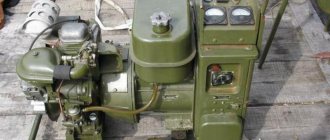
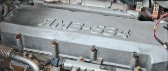
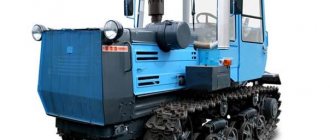
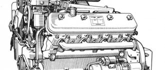
To drive various devices, special mechanisms are used - stationary motors. The air-cooled UD 2 engine is a prime example of stationary installations. It has a simplified design, is easy to repair and restore technical and operational characteristics. Most often, such equipment is used for technical means. The UD-2 engine is a carburetor 2-cylinder power unit. It is produced at the UMZ motor plant in the city of Ulyanovsk.
UD 2 engine design
This power unit includes the following components and systems:
- Carter.
- Distribution mechanism.
- Lubrication and cooling systems.
- Fuel system.
- Crank mechanism.
- Starting and ignition systems.
Technical characteristics of the UD 2 engine:
| Engine power | 6 – 8 horsepower |
| Type of fuel consumed | Low octane gasoline |
| Cylinder volume | 0.61 l |
| Number of crankshaft revolutions | 3000 rpm (maximum value) |
| Fuel consumption | 370 g/hp h |
| Power unit weight | 72 kg |
| dimensions | 0.55x 0.485x 0.556 m |
| Number of cylinders | 2 |
UD (engines)
In the USSR, over the years, several series of stationary gasoline engines were produced to drive electric generators, pumps, agricultural machines, and charge batteries. These same engines were widely used on small vessels.
Content
- 1 Series "L"
- 2 Series "UD"
- 3 Engine ZID-4.5 (UMZ-5)
- 4 Engine “2SD”
- 5 Engine “SD-60” B/3
- 6 Engine "ODV-300V"
- 7 Modifications of Moskvich engines
- 8 Modifications of GAZ, ZMZ, UMZ engines
- 9 Modifications of ZIL engines
- 10 Notes
- 11 Literature
Series "L" [ | ]
L series engines
(
Leninets
) were developed in the late 30s at the Ulyanovsk Motor Plant and were produced until the early 60s. The series included three engines, unified according to the cylinder-piston group: L-3/2, L-6/2 and L-12, respectively single-cylinder, two-cylinder and four-cylinder. The working volume of the cylinder is 300 cm3. Operating speed - 2000 rpm. Cylinder power 3 hp Engines are carburetor, four-stroke. Cooling is liquid. Lubrication - by splashing.
“L” engines were originally developed to drive electric generators, pumps, etc., but have also found application for boats.
Series "UD" [ | ]
UD
- a brand of multi-purpose small-displacement gasoline internal combustion engines produced by the Ulyanovsk Motor Plant.
stands
for Ulyanovsky Dvigatel
. The engines are four-stroke, air-cooled, with bottom valves. Since 1952, 3 main models and their modifications have been produced:
- UD-1 single-cylinder engines with a power of 4 hp. with bottom valves; 305 cm 3
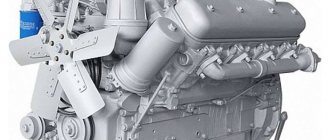
- UD-2 two-cylinder engines with a power of 8 hp. with bottom valves; 610 cm 3
- UD-4 four-cylinder engines with a power of 15 hp. with bottom valves; 1220 cm 3
Some features of the working components of the UD-2 engine
The engine crankcase consists of 2 halves made of cast iron alloy. A sealing element is installed between them - a special gasket, thanks to which engine oil does not leak out. There is a drain hole with a plug at the bottom of the housing. Through a special hatch located in the side of the crankcase, there is access to the parts of the crank mechanism and the oil filter.
The crankshaft is considered one of the main parts of the power unit. The shaft is made of special steel. The crankshaft is supported by ball bearings installed in the crankcase walls. At the ends of the shaft there are seals that prevent oil leaks.
Aluminum pistons are equipped with compression and oil rings.
A lubrication system is provided to lubricate the rubbing surfaces of components and engine parts. There is a special bath with motor oil with a capacity of 4 liters. Lubrication is carried out in two ways: using splashing and under pressure. Oil is supplied by a gear pump. The oil filter includes replaceable filter elements in the form of paper plates.
Interesting: To check the degree of oil pressure in the system, the design provides a special mechanical device. The sensor is made in the form of a metal pin. When this pin is extended out of the housing to a specified length, the oil pressure is considered normal.
Gasoline is supplied to the working cylinders using a K-16V carburetor. For ignition, a magneto with the M-68B1 index is used, equipped with a device that regulates the advance angle in automatic mode. Thanks to this unit, the UD-2 engine operates stably at different speeds.
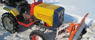
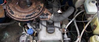
THE YOUNGER BROTHER OF “VLADIMIRTS”
The situation was further complicated by the fact that it was not possible to rationally place the generator and oil pump. They cannot be attached to the frame, and there is nowhere to attach them directly to the UD-2. Therefore, I used two spacers made of 50x25 mm steel channel, attached to the engine with M12 bolts. The mounting brackets for the pump and generator were welded to them. The place for the drive pulley of their V-belt drive was found at the front end of the crankshaft. There is a finned flywheel for forced cooling of the engine. I removed the flywheel, machined a landing journal on it, drilled four holes, cut an M8 thread and attached a pulley (from a GAZ-21 water pump) with four bolts. The belt tension is adjustable; to do this, you need to loosen the two bolts on the tensioner plate and, moving the plate down, tighten it again.
So, the power plant has four support points; The two front ones, belonging to the engine, are located on the lower side members of the frame, on rubber cushions, and the two rear ones, belonging to the UAZ gearbox, are located on the upper side members. The rear axle is located between the side members on special supports.
In addition, many more beams, crossbars, racks, crossbars and brackets are welded to the frame, which are intended for various elements of a complex tractor organism. For example, counterweights are suspended from the crossbar, the engine hood rests on the beam, the front axle is connected to a wide plate, the cabin is screwed to the struts and crossbars, and a two-spool hydraulic system distributor and a power hydraulic cylinder are attached to the brackets.
By the way, the spatial frame provided rich opportunities for arranging the necessary mechanisms within its confines. I had no problems, say, finding space for numerous hydraulic system units. In the space between the upper and lower side members, seemingly filled to capacity with the power plant, the rear axle, in addition to the already mentioned hydraulic distributor and hydraulic cylinder, there was also a voluminous hydraulic tank, hoses, distributor control levers, as well as an attachment that I mounted into the frame. later.
The hitch is designed for towing replaceable agricultural implements (plow, harrow, disker, etc.) and a cargo trailer. It consists of two shafts that rotate in bushings that are welded into the ends of the side members, as well as an earring, levers and adjustable power rods.
Later, during operation, it turned out that the mini-tractor did not have enough weight to work with a mounted plow. We had to weigh down its front end with two counterweights from Vladimirets, 20 kg each. With them, the “younger brother” went much softer, smoother and became more obedient to the steering wheel.
The front axle was also not easy for me right away. There was an oil pump where it needed to be attached. Therefore, the mounting point had to be moved a little back, and the bridge beam had to be made slightly curved - with the ends moved forward, so that the steering wheels remained in their intended place.
The beam was made from a rectangular steel pipe with a cross-section of 40×60 mm with allowances at the ends. For strength, I welded an overlay (from the same pipe) on the front, and a hinge bushing on top. Then I hung the beam from the counter swing unit, which was screwed from below to a wide and thick steel plate on the lower frame side members. As a swing unit I used a modified axle from a GAZ-53 car. The kingpin is a bolt made of hardened steel, fixed in the linkage bushing with a locking bolt. Bronze liners serve as friction bearings.
Having suspended the beam, I cut off its end allowances and used electric welding to secure the steering cups with combined pivot pins and axle shafts. I grabbed them together with the wheels to see how it all would look. Two words about the axle shaft. This double name is not accidental, since it is machined in the form of a single shaft, then heated in the flame of a gas burner and bent to an angle of 93°: one end of the shaft is a rotary axle, the other is a wheel axle shaft.
The steering is directly connected to the front axle. I made the steering column so that the steering wheel could be tilted toward or away from you, and even, if necessary, tilted forward when servicing the cabin and the entire tractor. To do this, I welded a tube to the front panel of the cab - a piece of the driveshaft of a GAZ-51 car. The column itself was taken from the MTZ-50 tractor. I removed everything unnecessary from it, leaving only the pipe and shaft. I connected the pipe and tube pivotally using parts of the cardan mechanism: I cut off the landing journals from the crosspieces, inserted them into the bearings of the tube, inserted the pipe between them and grabbed them with electric welding; then he carefully knocked out the bearings, took out the pipe, wrapped the necks with asbestos cord and welded them completely. The result is a fairly movable structure, fixed in the required position with a spring-loaded latch.
The column and steering mechanism (it is from Moskvich-412) are connected by a modernized cardan shaft (from the corresponding mechanism of the MTZ tractor), which allows the column to tilt back and forth. The upgrade consisted of the shaft being cut, fitted with a telescopic spline and fitted into place.
And the steering rods are from Moskvich-412, and are also adjusted to the location. The rotary levers are combined, welded: one end of the lever (with a pin) is Moskvich, the other is tractor.
The steering wheel is from Moskvich-412. But since its splined hub did not fit the pipe, I replaced it with a hub from the MTZ-50 steering wheel.
I must say that the mini-tractor turned out to be very maneuverable. The turning radius is only 5 m. So a 6 m wide road surface is enough to turn around in one go, without backing up or driving onto the side of the road. And a personal plot of even a few hundred square meters for him is the same as a field.
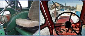
When the chassis was ready, I started decorating the exterior of the mini-tractor. Mentally imagining what its cabin and lining would look like, I decided: something like the one on the Vladimirets. And the windshield that I eventually found, I think it’s also from the T-25 tractor.
The skeleton of the cabin, including rear and front pillars and cross members, was assembled from sections of steel pipe with a cross-section of 40×40 mm, and the frame was made from sections of pipe with a cross-section of 20×20 mm. I made the front frame of the frame according to the dimensions of the windshield, taking into account the width of the rubber edging. The opening in the frame below the edging was welded with sheet iron 1 mm thick, the seams were processed with an emery wheel clamped in the chuck of an electric drill. There was an idea to make glass in a circle. But since the mini-tractor is used mainly in the warm season, I decided not to complicate the design of the cabin. For the same reason, I refused to use doors. And from the rain it is enough to have glass in front and a roof over your head.
I bent the roof from a sheet of iron. Having placed a thick board, I stamped two “ribs” of rigidity into the roof according to the markings, 100 mm wide and 3 mm deep, using a blunt chisel. I did this gradually, step by step, so that the sheet would not move.
The layout of the power plant and transmission (some frame elements are not shown):
1 — UD-2 engine; 2 — spacer (channel, 2 pcs.); 3 — clutch housing (from UAZ-469); 4 - KGIP-1 (from UAZ-469); 5 — support plate for Gearbox-1, standard; 6 — transition plate (steel, sheet s 14); 7 — Gearbox-2 (from GAZ-51); 8 — cardan mechanism; 9 — rear axle (from UAZ-469); 10—bridge support; 11 — power plant support, rear; 12 — power plant support, front (with rubber cushion).
Oil pump and generator drive:
1 - engine; 2 — driving pulley; 3 - V-belt; 4 — M12 engine mounting bolt: 5 — lower frame spar; 6 — front engine support; 7 — bracket for fastening the pump plate, right; 8 — M10 bolt for fastening the pump (2 pcs.); 9 — belt tensioner plate; 10 — pump pulley: 11 — generator mounting bracket; 12 — generator pulley; 13 — oil pump HIII-6 of right rotation; 14 — bearing housing; 15 — bearings 204; 16—key; 17 — splined pulley shaft; 18 splined pump shaft.
Attachment:
1 — hydraulic cylinder mounting bracket; 2 — upper frame spar; 3 — power hydraulic cylinder; 4 — lifting lever (2 pcs.); 5 — shackle for fastening the plow linkage rod; 6 — power lever; 7 — adjustable lateral rod (2 pcs.); 8 — traverse; 9 — lower frame spar; 10, 17 — upper and lower shafts (steel bar Ø 34); .11 — restrictive cheek (4 pcs.); 12 — bushing-bearing (steel pipe 40×2.5.2 pcs.); 13 — spacers (steel pipe 40×2.5); 14— bushing-bearing (steel pipe 45×2, 2 pcs.); 15 — traverse ears; 16 — clamp (2 pcs.); 18 — limit washer (2 pcs.)
Front axle:
1 — hinge bushing; 2 — cover (steel pipe 60x40x5); 3 — bridge beam (steel pipe 60x40x5); 4 — steering glass; 5—thrust spring ring; 6 — plug (oil-resistant rubber); 7 — pivot axle shaft; 8.11 — bearings 204; 9 — spacer sleeve; 10 — oiler (conditionally rotated to the image plane); 12—bearing 958305.
Steering:
1 — steering wheel; 2 — pipe (tube is not shown); 3 - shaft; 4 — telescopic spline connection; 5 — lower frame spar; 6 — steering mechanism; 7 — steering bipod; 8 — adjustable push rod; 9 — steering steering lever; 10 — front axle; 11—bridge support; 12 — M10 bolt (6 pcs.); 13 — transverse thrust; 14 — king pin; 15 — beam swing unit; 16 — liner (bronze, 2 pcs.); 17 — hinge bushing.
Steering column:
1 - pipe; 2 — spring-loaded latch; 3 - tube; 4 -5 — bearing cover; 6 — shaft fork.
Layout of controls and auxiliary equipment in the cabin and under the hood (roof, front axle beam and steering column are not shown):
1 - ignition coil; 2 - fuel pump; 3 — clutch hydraulic cylinder; 4 - relay regulator; 5 — main brake hydraulic cylinders; 6 — control devices; 7 — control lamp for turning on the “mass”; 8 — ignition switch; 9 — sound signal button; 10 — gas pedal; 11 — brake pedals; 12 — starter lock; 13 — switch for headlights and side lights; 14 — hydraulic distributor control levers; 15 — gearshift lever-2; 16 — battery; 17 — fuel tank; 18 — driver’s seat; 19 — battery switch (“ground”); 20 — hydraulic tank filler plug (on the floor); 21 — clutch pedal; 22 — gearshift lever-1; 23 - step.
In a similar way, I made the hood, consisting of four panels. The top and sides of the hood, bending their 10-mm edges inward, were connected by electric welding. And I inserted the cladding into the folds pre-flanged in the remaining panels and attached them with M4 screws.
I made the front wings according to the pattern. Boca also minted them. But unlike the roof and hood, it was not at the stage of preparations, but already finished products, when the wings were soldered.
The rear fenders and running boards were welded by autogenous welding to the cab frame and to the upper frame spar. Before doing this, I knocked out small indentations in the bottom of the footrests with a blunt core so that my feet would not slip.
The floor in the cabin was made of 3 mm sheet iron. I cut holes in it for the hydraulic tank filler neck and control levers. On the floor under the seat I placed the gas tank, battery and ground switch.
The pedals in the cabin are suspended, from a UAZ-452 car. With the help of an autogen, they are slightly curved upward for convenience. The difference with the UAZ is that there are two brake pedals: on the right and left sides. The brakes do not lock, although you can press both pedals with one foot at the same time.
On the instrument panel in the cockpit there are indicators for fuel level, engine oil temperature and pressure in the oil line, and an ammeter.
The ignition system of the mini-tractor is “battery”, like on the GAZ-51 car. I used the magneto that used to be on the UD-2 engine as a distributor, removing the ignition coil from it and inserting a dummy in its place - a piece of rubber cut to the shape of the coil. I did this so that the high voltage wire from the car ignition coil could be connected to the distributor cap. This ignition system makes engine starting more reliable.
I used the fuel pump from the interior heater of the Zaporozhets (such pumps were also installed on wheelchairs and Volyn cars). I must say that even without a dispenser it works perfectly! Fuel is supplied to it through a fine filter (often called a sump) from the UAZ vehicle. The pump is built in line between the sediment filter and the carburetor. Started from the electrical ground switch. After the carburetor float chamber is filled with gasoline, the pump automatically stops.
The charging current from the generator is monitored by the relay-regulator PP-350. I placed the front side lights in the headlights next to the low and high beam lamps, drilling holes in the reflectors for the light bulb sockets that are used to illuminate the instruments. The rear marker lights are located on the roof.
The mini-tractor is painted in the following colors: the lining, wheel rims, instrument panel and roof are yellow, the cabin and wings are red, the engine is painted with aluminum powder on nitro varnish.
Finally, a few words about what the mini-tractor can be coupled with. The main thing is a homemade single-axle trailer with an estimated load capacity of 500 kg, although, as it turned out, it can withstand more. The trailer body is tipping, equipped with a single-rod hydraulic cylinder from an agricultural machine. The height to which it raises the body is quite enough to dump bulk cargo. You can also unload the trailer by folding down the rear or side doors.
In addition, there is a homemade mounted plow. Its body is taken from a horse-drawn plow. A disc knife is installed in front of the ploughshare. The depth of the furrow is adjusted by a wheel or ploughshare. A small harrow is attached to the plow, which drags behind the moldboard, crumbling layers of earth.
M.ANTONOV, p. Loino, Kirov region.
We recommend reading
- OPEL ASTRA COUPE OPC X-TREME Few people know about the Deutsche Tourenwagen Veisterschaft racing in Russia. Maybe because only three brands of cars participate in them: Opel, Audi and Mercedes-Benz. It's interesting that...
- MODEL CONSTRUCTION 2007-04 IN THE ISSUE: Report of the issue: A. Polibin. "Autoexotica'2006" (1). Public design bureau: A. Starilov. From Volga - minibus (2); R. Cherepnev. Trainer's bike (4)….
Here you can evaluate the author's work:
UD2 engine modifications
Based on the main model, new engine versions are produced. To designate them, letter indices have been introduced into the marking of each option:
- engines designed to operate with a generator have the letter “G” in their designation; the UD2-G design includes: an electric starter, as well as a bell-shaped adapter; the ignition system has a magneto to ensure a constant advance angle;
- engines with the letter “C” are created for agricultural equipment (tractors, mini tractors);
- option “B” is used in floating craft, the “UD2-V” engines include a clutch mechanism and a reverse reverse gearbox, this motor includes specialized equipment in the form of a propeller and propeller shaft;
- motor brand UD2-T - version, produced for equipment engaged in road work, its design includes an electric starter, as well as a special adapter in the form of a flange for connecting to various types of gearboxes.
Engine UD-25 (UD25) for walk-behind tractor
Specifications
Stores where you can buy the engine and its analogues
general description
The UD-25 gasoline engine is a small-displacement carburetor four-stroke two-cylinder stationary engine used in agricultural, construction equipment and other units.
Application of ICE UD25:
- power plants;
- walk-behind tractors, mini tractors, cultivators, etc.;
- small vehicles;
- boats;
- road equipment;
- and so on.
Benefits and Features
Despite its long history of production (since 1967), the UD-25 engine has many advantages of modern engines:
- reliability;
- durability;
- ease of use;
- compactness;
- ease of maintenance;
- good power.
Other technical characteristics (TTX)
- Compression ratio: 6
- Engine fuel: gasoline A-76, A-91 according to GOST 2084-77
- Gasoline supply: diaphragm type fuel pump
- Carburetor of UD-25 engine: K-16M
- Air filter: inertial oil filter with filter element
- Air filter oil bath volume: 0.07 l
- Oil for gasoline engine UD-25: in summer (above + 5°C): diesel M-10G2 GOST 8581-78, diesel M-10V2 GOST 8581-78, automobile ASZp-10 TU 38-101267-72
- in winter (below + 5°C): diesel M-8-V2 GOST 17479.1-85, diesel M-8-V1 GOST 17479.1-85, automobile ASZp-10 TU 38-101267-72
Soviet oils can be replaced with analogues:
- M-10V2, M-10G2 – CB oils according to API and SAE 30 specification standards, for example, Shell Rotella TX 10W/30, Shell Rotella X SAE 30;
- M-8-B2 – CB oils according to API and SAE 20 classification standards, for example, Shell Rotella X 20/20W;
- ASZp-10 - domestic M-5z/10A, M-6z/10V, foreign Mobil Delvac 1330, Mobil Delvac MX 15W/40 and 10W/30, Shell X-100 SAE 15W-40, SSPMO (Shell).
Modifications of UD 25
At the buyer’s request, the UD25 engine was equipped with additional equipment necessary to achieve the engine’s operating goals. Depending on the installed super-complete modules, a letter designation was added to the model number “UD-25”.
Engines UD-25g
Motors “UD 25 g” were installed on gasoline electric generators and other units with a flange attached to the engine.
Dimensions: 61×50×56.5 cm, weight: 66 kg.
Additional modules for UD 25g gasoline engines include:
- adapter for connection to the equipped unit via a flange;
- electric starter ST-366 or ST-351B;
- toothed flywheel with half-coupling;
- screen for the ignition system against radio interference.
Engines UD-25s
The UD-25 modification with the letter “C” means that the motor is equipped with a single-stage reduction gearbox RO-2. Used to drive small-sized agricultural units and other devices that require low rotation speed of the output shaft.
Dimensions: 67×45.5×56.5 cm, weight: 61 kg.
Prices for the UD-25 engine
It is almost impossible to find new UD25 engines for sale at retail from stores; they can only be bought second-hand or even unused. Prices for used motors average 6,500 rubles. – the cost largely depends on the condition and year of manufacture of the internal combustion engine.
Upgraded UD 2M engines
As a result of numerous modernizations that were carried out in the late nineties of the last century, an additional prefix “M” appeared in the marking of power units. Engine UD 2 modernization: now the modern basic design is designated UD2-M1. There are several versions of UD 2M engines; their design and technical characteristics have received some changes:
- The UD2S-M1 power unit includes a fuel tank with a capacity of 20 liters and a RO-1 gearbox.
- The UD2T-M1 engine has an eight-liter fuel tank, which is located on top of the body. The filled amount of gasoline is enough for continuous operation for one and a half hours.
- The UD2ST-M1 power unit has the same fuel tank, in addition it includes RO-1.