Probably almost every motorist has heard about the 130th ZIL at least once in his life. Of course, this is a legendary car that left a big imprint on the history of the USSR automotive industry. But no less legendary is the motor itself from this device. Let's consider the main technical characteristics, device, as well as the complete process of maintenance and overhaul of this power unit.
The ZIL 130 (508) engine was installed on ZIL-130 and ZIL-131 trucks. The design of the ZIL 130 engine had many similarities with the engine of the executive model ZIL-111, but in general the engine models had a low degree of unification. The engine volume was reduced to 6 liters, a two-chamber carburetor was installed and it was equipped with a speed limiter. Seven-liter engines are called ZIL-375 and are used in trucks of the Ural Automobile Plant. The increase in volume was achieved by increasing the radius of the cylinders to 108 mm, while maintaining the piston stroke of 95 mm.
Adjusting valves ZIL 130 - 4 rules
Adjusting engine valves on a ZIL 130 car, as on other engines, requires knowledge of four basic rules
- Where is the first cylinder located? Because all visible marks on the pulleys correspond to the position of the piston of the first cylinder at top dead center (TDC).
- In what position of the crankshaft is the piston of the first cylinder at TDC during the compression stroke? In this position, the intake and exhaust valves are closed and the valve clearances are adjusted.
- It is necessary to know the operating order of the cylinders of a particular engine. That is, which next cylinder will start working. To turn the crankshaft and begin adjusting the next cylinder in sequence.
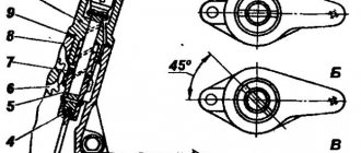
- It is necessary to know at what angle the crankshaft must be turned to bring the piston of the next cylinder to TDC during the compression stroke
These four rules apply to all four-stroke internal combustion engines. Having mastered these points well, you can adjust the valves without the help of specialists.
Valve adjustment 402 Gazelle engine carburetor
Despite its amazing maintainability, the ZMZ-402 was not very successful in its technical characteristics. The lower location of the camshaft, the presence of long pushrods, and the not very high quality of the parts, all this increases the vibration load on the gas distribution mechanism, and therefore reduces the time interval between adjustments. If the motor is used carefully, without operating under maximum load and without sudden starts, then adjustments must be made every 15 thousand kilometers. If the driver likes quick starts, driving at low speeds and high gears, and is also forced to carry heavy loads or drive through the mountains, then the mileage is reduced to 10 thousand kilometers. If you use gasoline that does not match the cylinder head (cylinder head), then regardless of the ignition settings, the valves must be adjusted after 5–6 thousand kilometers . This will reduce the likelihood of valve burnout and loss of compression.
This is interesting: Do-it-yourself adjustment of ZIL 130 valves
Description of adjustment work for the engine
The ZMZ engine is popular among domestic car enthusiasts due to its economical fuel consumption and ease of maintenance. But the engine’s amazing maintainability did not rid its design of some technical flaws.
The assembly of low-quality parts and the complex arrangement of spare parts inside the engine place a large load on the working mechanism, which increases the degree of its wear.
The ZMZ-402 engine requires a special approach, which involves adjusting valve clearances, which is carried out on average every 15,000 km. The lack of a gas distribution function in the engine forces vehicle owners to make adjustments for the following purposes:
Adjusting the valves of the ZMZ-402 engine
- avoiding valve burnout;
- increase in pressure in the engine cylinder;
- uniform filling of the cylinder with fuel;
- trouble-free removal of exhaust gases.
The frequency of adjustment work depends entirely on the type of vehicle load and correct use of fuel. If the engine is used carefully and is not driven to maximum speeds, then the valves should be adjusted every 15,000 km. If the vehicle is used to transport large cargo, adjustments are carried out every 10,000 km.
If a car owner uses gasoline that does not correspond to the designated brand as fuel, then the risk of valve burnout and loss of pressure in the cylinders increases significantly. Stable adjustment of thermal clearances every 5000-6000 km will save the engine from premature wear, and individual parts of the engine will be protected from overheating and failure.
Adjusting valves GAZ 402
The ZMZ-402 engine has been produced since 1985; it first appeared on the transitional GAZ 24M models. It is also widely used
on Gazelles. The eight-valve engine has a lower camshaft and an overhead valve arrangement; its gas distribution mechanism contains the following parts:
- camshaft, it rotates in five supports of the cylinder block;
- camshaft, transmits movement from the crankshaft to the camshaft;
- 8 pushers, driven by camshaft cams;
- 8 aluminum rods;
- the rocker axis, on which the rocker arms themselves are located (8 pcs.) with adjusting screws;
- exhaust and intake valves located in the cylinder head.
When the camshaft rotates, the valves in the cylinder head rise and fall. Just like all other modern engines, the ZMZ-402 operates on a four-stroke circuit:
- first, an intake occurs into the internal combustion engine, the air-fuel mixture fills the cylinder;
- then the mixture is compressed in the cylinder, and it is ignited by a spark from the spark plug;
- working progress occurs;
- The last step in the process is the release of exhaust gases.
When compression occurs, both valves are closed and sealed - the valves are adjusted in this position. In order for the combustion chamber to be sealed at the moment of compression, there must be a thermal gap between the valve stem and the rocker arm - if there is none, when the metal expands on a hot engine, the valve will not fit tightly to the seat (seat), the engine may lose power, and in some cases In some cases, it will not start at all.
Setting TDC at the moment of compression
The problem arises when the piston becomes in the correct position to adjust the valves of the first cylinder. The piston must be at TDC during the compression stroke. There is a mark on the crankshaft pulley. It needs to be aligned with the TDC designation on the scale.
Indeed, the piston of the first cylinder will rise to TDC. But it is necessary to make sure that it is in the compression stroke. Because for the full cycle of engine operation from the first to the eighth cylinder. The piston becomes twice at TDC. We are only interested in one of its positions. This position can be determined in several ways.
- If the engine is in working order on the car. You can remove the tip from the spark plug wire going to the first cylinder. And turn the crankshaft with the ignition on. At the moment a spark jumps between the wire and ground. You should place a mark on the pulley with the TDC designation on the scale. The spark will jump before the piston reaches top dead center. And by setting the marks, the piston will move to the desired position.
- You can unscrew the spark plug of the first cylinder and plug the spark plug hole with a paper plug. When cranking the crankshaft, the plug will shoot out. All that remains is to align the mark on the pulley with the TDC mark on the scale. You can simply plug the hole with your finger. When air starts to come out from under it, all you have to do is align the marks. This indicates that compression is forming in the cylinder. Compression begins. Therefore the valves are completely closed.
- Visually, the TDC position is determined by the rocker arms. In the compression position when the piston approaches TDC, the rocker arms are not movable. The valves are closed. In the second position, when the piston approaches TDC, one valve closes. The second one, after passing TDC, begins to open immediately. If the valves are stationary, all that remains is to align the marks.
After the piston of the first cylinder is in the correct position, it is necessary to adjust the valves of the first cylinder.
Adjusting valves ZIL 130
To adjust the valves, you need to loosen the lock nuts of the adjusting screw. A probe with a thickness of 0.25 or 0.3 mm is installed between the valve and the rocker arm. If a 0.25 mm probe is installed. That is when you tighten the adjusting screw. The rocker arm clamps the dipstick. The probe should move with little effort. If a probe with a thickness of 0.3 mm is installed, the force must be stronger. The dipstick moves but the rocker arm should not put pressure on the valve, otherwise it will open and the adjustment will not be correct. Valve adjustment on a ZIL 130 car provides for equal clearances on the intake and exhaust valves. After adjustment, the lock nuts must be tightened. In this case, the adjusting screw must not be allowed to turn. Therefore, when tightening, it must be held with a screwdriver.
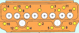
The order of operation of the ZIL 130 engine cylinders
To adjust subsequent valves, you must know the operating order of the cylinders. He's next
That is, after adjusting the first cylinder, you should adjust the valves of cylinder 5, then 4, and so on in order.
Cranking the crankshaft
In order to bring the cylinder pistons to TDC one after another in order, it is necessary to rotate the crankshaft at the same angle each time. This angle is
90 degrees.
So as not to make a mistake. you can apply markings on the pulley yourself
And turn the crankshaft according to your marks
You can simply unscrew all the spark plugs and move the piston of each cylinder to TDC by touch using a screwdriver.
The rotation looks like this: The valves of the first cylinder are adjusted when the mark on the pulley and the scale are aligned. Next, the crankshaft is rotated clockwise 90 degrees and the valves of cylinder 5 are adjusted. Then the crankshaft is rotated 90 degrees. The valves of cylinder 4 and so on up to cylinder 8 are adjusted. According to the operating order of the cylinders. You can easily understand why the crankshaft rotates 90 degrees.
During one engine cycle, from the first to the eighth cylinder, the crankshaft rotates twice. The camshaft makes one revolution. Two revolutions of the crankshaft are 720 degrees, two times 360. There are 8 cylinders in operation. So, we divide 720 by 8 and we get 90 degrees.
If there were 6 cylinders, then divide 720 by 6 to get 120 degrees; four-cylinder engines are rotated 180 degrees to adjust the valves.
Adjusting valves ZIL 130 in two turns
The valves can be adjusted quickly in just two revolutions of the crankshaft.
The first revolution is made to align the mark on the pulley with the TDC mark on the scale on the compression stroke of the first cylinder. Just as it was described. In this position the valves of the following cylinders are adjusted:
Intake and exhaust cylinder 1
The remaining valves are adjusted after turning the crankshaft one turn 360 degrees. In this case, the mark on the pulley and the TDC mark on the scale must again be aligned.
Schematically it will look like this
Adjusting the valves on the ZIL 130 car engine is similar to adjusting the valves on the GAZ 53. The same principle is used for adjusting the KamAZ valves and the valves on the YaMZ 238 engine. The difference is in the adjustment methods. Each engine has design features. Which allow you to make adjustments more conveniently. But the basic principle is the same for all V-eight cylinder engines
Source
The order of operation of the cylinders ZIL 130 v8 diagram
Correct installation of the ignition on a car is important when operating it. Incorrectly installed ignition leads to excessive fuel consumption. Ignition too late leads to loss of engine response and slow acceleration of the vehicle.
With early ignition, detonation combustion occurs, which leads to a decrease in engine power and rapid wear of parts of the crank mechanism.
Sequence of work:
- Remove the distributor-distributor cover and rotor.
- Check and, if necessary, adjust the gap in the breaker contacts.
- Put the rotor in place.
- Set the octane corrector needle to the zero division.
- Disconnect the vacuum regulator tube.
- Install the piston of the first cylinder in. m.t. during the compression stroke. For this:
a) remove the spark plug of the first cylinder;
b) close the spark plug hole with your finger and, turning the crankshaft with the starting handle, determine the beginning of air compression by the piston in the cylinder;
c) align the mark on the crankshaft pulley with the pointer (Fig. 1).
- Turn on the ignition.
- Turn the breaker-distributor clockwise until the breaker contacts close.
- Connect one wire of the portable lamp to the low voltage terminal of the breaker-distributor, and the other to its body.
- Slowly turning the body of the breaker-distributor counterclockwise, set the contacts to the beginning of opening.
- Stop the rotation of the housing when the light flashes.
- Secure the body of the breaker-distributor, install the rotor, replace the cover and high-voltage wires.
- Connect the high voltage wires to the spark plugs.
- Check the accuracy of the ignition installation. For this:
a ) warm up the engine to a water temperature in the cooling system of 80-85° C;
b) driving a car along a flat section of the road in direct gear at a speed of 25-30 km/h, press the throttle pedal all the way and accelerate it to a speed of 60 km/h.
d) listen to the engine.
Technical conditions.
High voltage wires must connect the side terminals of the distributor cap to the spark plugs, according to the engine operating order (1-5-4-2-6-3-7-8), taking into account that the rotor rotates clockwise.
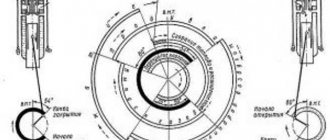
Rice. 1. Installing the piston of the first cylinder in c. m.t.:
1 — starting handle; 2 - ratchet; 3 - pulley; 4 — marks on the pulley; 5 — ignition installation indicator.
Ignition control on the ZIL-130 engine is carried out in the following sequence:
- install the piston of the first cylinder in c. m.t. on the compression stroke; To do this, turn the crankshaft using the starting handle until the mark on the pulley aligns with the mark on the ignition setting indicator.
- turn the crankshaft counterclockwise until the mark on the crankshaft pulley aligns with the 9° mark on the ignition position indicator.
- loosen the bolt securing the upper octane corrector plate and turn on the ignition.
- The body of the breaker-distributor is turned counterclockwise and its contacts are set to the beginning of opening (at the moment the contacts open, the control lamp will light up).
- tighten the bolt securing the upper plate of the octane corrector and attach the tube to the vacuum machine.
The ignition installation is fine-tuned while the vehicle is moving. To do this, accelerate it from 30 to 60 km/h and, by sharply pressing the throttle pedal, fully open the throttle valve. A sign of correct ignition installation is light detonation knocks, which disappear when the speed decreases to 45 km/h. With early ignition, sharp detonation knocks are heard, but with late ignition, they are absent. In this case, the ignition setting is adjusted by moving the arrow of the upper plate.
Rice. Indicators for ignition installation:
A - on the ZMZ-ZZ engine; b - on the ZIL-130 engine; c - turning on a portable lamp when installing the ignition.
Characteristics
The third most resistant to Russian conditions, the 6-liter engine has a V-shaped configuration, eight cylinders, a displacement chamber diameter of 100 millimeters, a 95 mm piston stroke and two valves. The engine operates at a rated power of 150 horsepower, makes 3200 revolutions per minute and has a dual-chamber fuel supply. The engine has a liquid cooling system.
This unit was reduced in volume to 6 liters, which helped reduce fuel consumption. It featured a two-chamber type carburetor system with a special speed limiter. It is worth pointing out that the ZIL 130 engine model has modifications.
The first Soviet cars were equipped with classic carburetor engines with V-shaped working displacement chambers. In such a system, the engine reached a volume of 5200 cubic centimeters. After some time, the developers became convinced that the technology did not develop the required potential. Because of this, a V-shaped model with 8 cylinders was manufactured. Thanks to the increase in the number of latest parts, it was possible to increase the power of the power unit to 150 horsepower. Neither the 357 brand engine nor the 131 brand unit developed such potential. Subsequently, the designers created a version that allowed the driver to accelerate to 90 km/h thanks to the four-stroke cycle of the work performed and the overhead valve arrangement.
Description
The ZIL 130 power unit is an engine with eight cylinders that performs four strokes in one working cycle. Fuel is supplied using a carburetor, which ensures a constant supply. The arrangement of the cylinders at an angle of 90° (“v” figuratively) gives the unit power, and at the same time gives the motor light weight. The power plant is cooled using liquid. The ZIL 130 engine lubrication system is combined, oil is supplied to the engine with pressure, the rest is sprayed.
The power plant is structurally similar to the ZIL 111 modification, however, the interchangeability of engine parts is small. One hundred and thirtieth of a smaller volume, the carburetor used on the engine consists of two chambers. The seven-liter unit, which is labeled as ZIL 375, is used in vehicles under the Ural brand.
Important! One hundred and thirtieth installations are unified, parts of the units are interchangeable. However, it must be taken into account that parts and mechanisms marked ZIL 130 AGE or BE are not suitable for the ZIL 130 product.
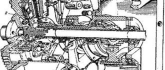
Engine ZIL 130:
Principle of operation
For a general understanding of what the ignition order of the ZIL 130 8 cylinders looks like, it is necessary to point out the principle of engine operation. The motor operates thanks to the functioning of the crank, gas distribution mechanism, cooling system, lubrication and power supply. During fuel combustion, the crank mechanism expands and transforms the movement of the crankshaft piston. It contains blocks of working displacement chambers with crankcases, pistons, connecting rods with other parts.
The cylinder block is considered the main part of the power mechanism. All elements are attached to it. They contain combustion chambers that are cooled through a specially designed cavity. There are also parts responsible for the proper functioning of the distribution mechanism of the incoming gas: intake with exhaust fuel channels and guide devices. The camshaft is presented in the right and left cylinder bank. Rotating, its rod presses on the screw of the mechanism, presses on the surface of the valve and opens the channel in the heads of the working displacement chambers. The camshaft acts on the chamber pushers. An overhead valve gas distribution mechanism improves the shape of the combustion chamber, fills the cylinders and creates the conditions under which the fuel mixture burns. The improved shape of the camera increases the power of the device.
The crankshaft includes connecting rod journals with counterweights. The location of the connecting rod journals in the crankshaft depends on the number of cylinders. In a V-shaped engine, there are several times fewer of them than working internal combustion chambers, since several connecting rods are installed on one shaft connecting rod journal for the left and right row of cylinders. The parts are made at different intervals so that the working cycles alternate evenly. The eight-cylinder V-engine has four journals, which are at a 90-degree angle.
In addition to the necks, the VSD chambers contain valves. They open and close depending on the direction of the pistons and are necessary to fill the engine with fuel.
To prevent the engine from overheating during operation, the combustion chamber block and the starting heater have taps with threaded holes that let in coolant. Forced circulation of coolant is carried out using a water pump, and enhanced cooling occurs due to intensive airflow into the radiator.
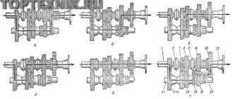
Distribution mechanism
The crankshaft and camshafts are connected by gears, so they work in strict coordination. From the camshaft cams through pushers and rods, movement is transmitted by rocker arms, which open the valves, and the valves are pressed to their seats by a spring.
During operation, all parts of the mechanism must be lubricated, cooled, and the working process must provide power to the combustible mixture. All shown mechanisms and systems form a single power unit, the ZIL-130 engine
Crank mechanism
Ignition principle
To better study the topic of the order of operation of the cylinders of the ZIL-130 engine, you should know how ignition occurs. You should know its order in order to assemble the engine during a major overhaul and when removing the distributor. To install the ignition on a ZIL 130, you must perform the following procedure:
As a result, the ZIL-130 engine serves as the standard of the Soviet power engine for a reason. The order of operation of the ZIL cylinders is complex, but well thought out, thanks to which trucks with it move as smoothly, reliably and with the least amount of fuel consumption. The four-stroke eight-cylinder unit with a carburetor fuel supply system is one of the most reliable Soviet-type devices, and therefore remains in demand to this day. For better maintenance and major repairs of equipment, you should carefully study the design features and operating procedure of the engine presented above.
Source
Characteristics of the ZIL 130 engine
The ZIL 130 engine has a V-shaped eight, which was often used on Soviet trucks. This is considered the third engine in terms of reliability, after YaMZ and KAMAZ. This power unit was also installed on GAZ 53 trucks as a modification, but this modification was not widely used.
| Parameter | Meaning |
| Configuration | V |
| Number of cylinders | 8 |
| Volume, l | 6,0 |
| Cylinder diameter, mm | 100 |
| Piston stroke, mm | 95 |
| Compression ratio | 6,5 |
| Number of valves per cylinder | 2 (1-inlet; 1-outlet) |
| Gas distribution mechanism | OHV |
| Cylinder operating order | 1-5-4-2-6-3-7-8 |
| Rated engine power / at engine speed | 110.4 kW - (150 hp) / 3200 rpm |
| Maximum torque/at engine speed | 401.8 N•m / 1800-2000 rpm |
| Supply system | Carburetor fuel supply, K-88A carburetor, two-chamber, with accelerator pump and economizer |
| Recommended minimum octane number of gasoline | 76 |
| Environmental standards | Euro 0 |
| Weight, kg | 440 |
Design
Four-stroke eight-cylinder gasoline with a carburetor fuel supply system, a V-shaped (double-row) arrangement of cylinders and pistons (the angle between the cylinder rows is 90°) rotating one common crankshaft, with a lower camshaft.
The engine has a closed-type liquid cooling system with forced circulation. Combined lubrication system: under pressure and splashing. Cylinder block
The ZIL 130 cylinder block is cast from cast iron, with a load-bearing water jacket and insertable wet liners. To increase rigidity, the water jacket is divided by partitions into closed power circuits. The cylinder liners are cast from SCh18-36 cast iron with a ferrite content limited to 5%. An insert made of corrosion-resistant austenitic cast iron is pressed 50 mm into the upper part of the liner (this ensures a liner life of up to 200 thousand km). The thickness of the sleeve is 7.5 mm, the height of the sleeve is 188.5 mm. The camshaft is installed in the cylinder block.
| Parameter | Meaning |
| Material | Ductile iron |
| Cylinder diameter, mm | 101,48 – 101,54 |
| Diameter of boring of crankshaft supports (for main bearings), mm | 79,500 — 79,525 |