02/09/2022 6 552 Ignition system
Author: Ivan Baranov
The engines of modern vehicles consist of many different mechanisms and components. And none of them is superfluous - each unit performs a specific function, one way or another affecting the operation of the motor as a whole. From this material you will learn what magneto structure is and how it works, and why this element is needed.
[Hide]
Magneto, or in search of a spark
Magneto is a magnetoelectric alternating current generator that creates electrical discharges between the electrodes of the spark plug to ignite the working mixture in the cylinders of internal combustion engines.
The operation of a magneto is based on the principle of electromagnetic induction.
The essence of induction is as follows: when a magnetic field is crossed by a closed conductor, an electric current arises in this conductor. When electric current passes through a conductor, a magnetic field is created around that conductor.
Magnetic field is the space around a magnet in which magnetic lines of force (or magnetic flux) pass. These lines are located denser between the poles of the magnet.
Alternating current can be excited in a conductor by rapidly changing the direction of the magnetic flux crossing it, for example, by turning a magnet around a wire coil. The operation of a magneto with a rotating magnet is based on this principle.
As the magnet rotates, the magnetic flux passing through the rod changes in magnitude and direction; As a result, an electric current arises in the winding, first in one direction and then in the other.
The capacitor serves to improve the operation of the magneto. With a capacitor, a strong spark is formed, without it, a weak spark is formed.
A capacitor is connected in parallel with the breaker contacts in order to reduce the sparking that occurs when the primary current is interrupted at the breaker contacts.
How does a magneto work?
When the magnet rotates, it excites a current in the primary winding, which is short-circuited by the contacts of the breaker.
When the current in the primary circuit reaches its maximum, the breaker contacts open. Because of this, the primary current is instantly interrupted. The magnetic field that was created by the primary current also disappears. This sudden change in the magnetic field excites a high voltage current in the secondary circuit, which can break the gap between the electrodes of the corresponding spark plug. Further rotation of the magneto rotor causes the formation of a new spark, etc.
How to check the technical condition of the magneto?
During everyday operation, the functionality of the magneto can be checked as follows: connect the high-voltage wire to the high-voltage terminal and hold the other end of the wire at a distance of 5-7 mm from the magneto body, sharply turn the rotor in the direction of rotation. In this case, a correctly assembled and adjusted magneto, when the rotor is sharply turned, should give a spark that ensures breakdown of the above gap. If there is no spark or it is weak, check the serviceability of the magneto and wire insulation.
SPECIFIC MALFUNCTIONS AND METHODS OF THEIR ELIMINATION
| Malfunctions | Probable Cause | Trouble-shooting |
| 1. Interruption of sparking | Contacts are oily or burnt | Clean the contacts with a chamois cloth soaked in clean gasoline or file the contacts if they are burnt |
| The gap between the contacts has not been adjusted | Adjust the gap | |
| The breaker lever cushion is worn out | Replace the breaker lever with a new one Adjust the gap | |
| The outline is out of adjustment | Adjust the gap | |
| Capacitor broken | Replace capacitor | |
| Magneto doesn't spark | Break in the primary or secondary circuit of the transformer | Replace transformer |
| Short to ground in primary circuit | Eliminate short circuit | |
| Breakdown of high-voltage wire insulation | Replace wire | |
| 3. Magneto gives a weak spark | Capacitor broken | Replace capacitor |
Disassembly and side magneto.
– remove the magneto from the engine; – clean it of dust and oil and disassemble it in the following order: – use a socket wrench to unscrew the nut securing the ignition timing automatic, remove it and remove the key from the groove; – move the latch aside, remove the breaker cover; – unscrew the four screws securing the cover, remove the cover; – remove the magneto rotor from the housing; – unscrew the transformer mounting pins and remove the transformer from the housing.
Reassemble the magneto in reverse order.
To replace the breaker contacts, proceed as follows:
– move the latch aside, remove the breaker cover; – unscrew the screw securing the connecting conductor; – unscrew the screw securing the breaker plate to the magneto cover, remove the breaker plate; – unscrew the screw securing the breaker spring; – remove the lock washer from the lever cushion axis, remove the lever with the cushion assembly from the axis; – unscrew the screw securing the contact post, remove the contact post from the axis.
Reassemble the breaker in the reverse order.
Luck with searching! But it’s easier to replace the magneto with a new one or send it to the service department (if there is a warranty, this can be done for free).
Motoblocks salute (agate), favorite, micron "lander", Neva. | Topic author: Vladimir
Hello to all classmates. NEVA walk-behind tractor, Robin Subaru EX-21.7.hp engine The decompressor levers are on the camshaft sprocket and it broke off. I removed it completely.
Grishin Boris (rn3z3517) As far as I know, the designer did not foresee that the Russians would work without a decompressor.
What’s more, it won’t start, and if it tries to start, it can tear your hands out due to the kickback.
Grishin Boris (rn3z3517) All I found: the decompressor only comes complete with a camshaft sprocket.
On others this is not the case. In any case, I didn’t find it.
Alexey (Hemanta) apparently without a decompressor the crankshaft does not spin up to the speed required for starting
Grishin Boris (rn3z3517) That's right.
-Valera (Tamasa) in theory should start but with recoil, the reason may be different: namely, when it was assembled, were the marks on the crankshaft and camshaft gears correctly aligned?
Dan (Torrance) I have 7.5 horses. Where is the decompressor?
Grishin Boris (rn3z3517) Follow the link above and look at the camshaft sprocket there... The decompressor itself sits there on it.
Grishin Boris (rn3z3517) The Subaru internal combustion engine does not have gears. There the camshaft is driven by a chain. The camshaft itself is located in the head.
That's why there are asterisks. There is a gear there only in the speed controller drive.
Dan (Torrance) I'm starting it up. There was never any return.
Grishin Boris (rn3z3517) Me too. But when the valve clearances are increased or the decompressor itself is damaged (you need to be able to do this), then YES. The return is such that it doesn’t seem like much. Or not start at all. The decompressor allows you to accelerate the crankshaft to starting speed and then, when the set speed is exceeded, it turns off, the internal combustion engine makes flashes and picks up speed.
Grishin Boris (rn3z3517) Do not post misinformation. The topic is about the Subaru internal combustion engine, and what did you put up? Why are you deceiving a person? In the Subaru internal combustion engine there are no gears on the camshaft and never have been. There is a chain drive to the camshaft.
Grishin Boris (rn3z3517) Subaru: camshaft sprocket with decompressor.
Below is the timing chain.
Grishin Boris (rn3z3517)
Vladimir (Marini) this sprocket and camshaft are two in one. In the photo you can see the dicampresor dog. this infection broke off in me, I carefully pulled it out with tweezers through the removed valve cover and it didn’t go deeper. I found it in one place for 1800 rubles.
Grishin Boris (rn3z3517) So I found the same thing and also only in one place. Link above in the feed. And the same price.. Post from January 17th.
Vladimir (Marini) the Chinese have plenty of analogs for Honda spare parts and the prices are normal, especially in St. Petersburg online stores. Well, I don’t like this Subaru and the engines and spare parts for them are expensive.
Grishin Boris (rn3z3517) The engine itself is good. And here is the PRICE. The most expensive, as are the spare parts for it. Amers are even a little cheaper.
Vladimir (Marini) maybe I was unlucky with this engine, it worked fine for a year and a half, then it started working as if it was feeling nauseous. I put all sorts of spark plugs on and blew out the carber, it helped, but not for long and he had work to do, it was time to plow three gardens and take out the garbage sometimes. In general, I bought it. champion-9l.s works great, but I decided to try to make this one. It doesn’t work, I’ll try to sell it for spare parts.
Grishin Boris (rn3z3517) Look at one more point: the quality of gasoline. I know how, because of low gasoline, a friend of his car agreed to repair his internal combustion engine, but necessity drove him on the road. There I topped it up at another gas station and the car was replaced. The carb is not blown out, but washed with a special fluid for flushing the carburetor. Available at gas stations.
I also had a problem with candles on my old NEVE... I was tormented to the point of laughing. Afterwards they suggested what and how to rinse it. After washing, they flew over like saints. That the new one worked. There is also a filter in the fuel tap, not everyone knows this. That’s where “happiness” gathers, too.
Tags: How to start a Neva walk-behind tractor with a Subaru engine
Design and operation of magneto PD-10UD
Tractors produced by the Minsk Plant are mainly equipped with an M124-B1 magneto, which has right-hand rotation due to a flanged half-coupling rotated by a PD-10 gear, and a 27-degree ignition timing angle.
To perform its functions, the M124-B1 magneto is equipped with the main mechanisms that ensure its operation: a rotor, a transformer and an interrupter unit.
The alternating current generated by the rotor assembly during its rotation is increased by the secondary winding of the transformer to its value of –10-15 kW and supplied to the breaker assembly. The formation of a spark that ignites the fuel in the spark plug occurs at the moment the breaker transmits a current that has reached its maximum level in the primary winding of the transformer.
Walk-behind tractor ignition system: how to set the ignition yourself
The ignition system of a walk-behind tractor is an important element of an agricultural unit. Its task is to form a spark to ignite the fuel. Periodically, it is necessary to repair the ignition of the walk-behind tractor due to incorrect operation or wear of the main parts of the unit. The breakdown must be repaired as quickly as possible to prevent wear and tear on other spare parts and systems.
Magneto upgrade
To carry out this procedure you will need:
- Magneto coil
- Stationery knife
- If necessary, nail polish, electrical tape
Photo 1
It’s very good if you find an old, unnecessary and even non-working magneto coil in your garage! And you will do the procedure described below with it. And your working one can be removed and preserved with the mark “Working”. You can always use it if someday you change your mind and abandon this design that I propose
Pay attention to the coil body. If the coil windings are filled with plastic, you will not be able to do anything with such a coil.
It’s good if you come across a coil wrapped in paper (as in the photo). If you do not have a spare unnecessary coil, you can remake your own one, but keep in mind that you will not regret the work done and will, with the help of an improved magneto, get one hundred percent results for a long time. Also keep in mind that you will have to work with the coil very carefully.
Photo 2
Photo 3
So, the reel is in your hands. Using a utility knife, remove the top insulation. Next, along with any insulating paper that comes across, carefully cut off the top winding. The wire will represent a hair. This is a high voltage winding. There are 18,000 turns. The winding thickness of such a winding is about 7-8 mm. Below it is the primary winding of the transformer. Don't touch her! Do not touch with a knife! The closer you get to it, the softer the knife cuts should be. Be careful. Between these windings there is still a decent layer of insulating material in the form of paper. It will signal you that you are approaching the primary winding. This procedure took me about 40 minutes. If you accidentally touch (scratch) the primary winding with a knife, varnish the wire. It’s good if you don’t remove the insulating layer of the primary winding. As in photo 2. If you have removed it, place a piece of electrical tape under the metal mustache so that it does not contact the main winding, and then wrap the primary winding in one layer with the same electrical tape. Instead of electrical tape, you can use paper and thread on top of the paper. The edge of the thread can be varnished to prevent it from unwinding. In the primary winding, one end goes to ground (core), the second through this mustache to the wire on the side.
So, the secondary high-voltage winding has been removed. The primary winding is insulated. Insert the coil into the magneto housing and connect its wire to the same location. Next let's move on to...
Magneto, or in search of a spark
Magneto is a magnetoelectric alternating current generator that creates electrical discharges between the electrodes of the spark plug to ignite the working mixture in the cylinders of internal combustion engines.
The operation of a magneto is based on the principle of electromagnetic induction.
The essence of induction is as follows: when a magnetic field is crossed by a closed conductor, an electric current arises in this conductor. When electric current passes through a conductor, a magnetic field is created around that conductor.
Magnetic field is the space around a magnet in which magnetic lines of force (or magnetic flux) pass. These lines are located denser between the poles of the magnet.
Alternating current can be excited in a conductor by rapidly changing the direction of the magnetic flux crossing it, for example, by turning a magnet around a wire coil. The operation of a magneto with a rotating magnet is based on this principle.
As the magnet rotates, the magnetic flux passing through the rod changes in magnitude and direction; As a result, an electric current arises in the winding, first in one direction and then in the other.
The capacitor serves to improve the operation of the magneto. With a capacitor, a strong spark is formed, without it, a weak spark is formed.
A capacitor is connected in parallel with the breaker contacts in order to reduce the sparking that occurs when the primary current is interrupted at the breaker contacts.
How does a magneto work?
When the magnet rotates, it excites a current in the primary winding, which is short-circuited by the contacts of the breaker.
When the current in the primary circuit reaches its maximum, the breaker contacts open. Because of this, the primary current is instantly interrupted. The magnetic field that was created by the primary current also disappears. This sudden change in the magnetic field excites a high voltage current in the secondary circuit, which can break the gap between the electrodes of the corresponding spark plug. Further rotation of the magneto rotor causes the formation of a new spark, etc.
How to check the technical condition of the magneto?
During everyday operation, the functionality of the magneto can be checked as follows: connect the high-voltage wire to the high-voltage terminal and hold the other end of the wire at a distance of 5-7 mm from the magneto body, sharply turn the rotor in the direction of rotation. In this case, a correctly assembled and adjusted magneto, when the rotor is sharply turned, should give a spark that ensures breakdown of the above gap. If there is no spark or it is weak, check the serviceability of the magneto and wire insulation.
SPECIFIC MALFUNCTIONS AND METHODS OF THEIR ELIMINATION
| Malfunctions | Probable Cause | Trouble-shooting |
| 1. Interruption of sparking | Contacts are oily or burnt | Clean the contacts with a chamois cloth soaked in clean gasoline or file the contacts if they are burnt |
| The gap between the contacts has not been adjusted | Adjust the gap | |
| The breaker lever cushion is worn out | Replace the breaker lever with a new one Adjust the gap | |
| The outline is out of adjustment | Adjust the gap | |
| Capacitor broken | Replace capacitor | |
| Magneto doesn't spark | Break in the primary or secondary circuit of the transformer | Replace transformer |
| Short to ground in primary circuit | Eliminate short circuit | |
| Breakdown of high-voltage wire insulation | Replace wire | |
| 3. Magneto gives a weak spark | Capacitor broken | Replace capacitor |
Disassembly and side magneto.
— remove the magneto from the engine; — clean it of dust and oil and disassemble it in the following order: — use a socket wrench to unscrew the nut securing the ignition timing automatic, remove it and remove the key from the groove; — move the latch aside, remove the breaker cover; — unscrew the four screws securing the cover, remove the cover; — remove the magneto rotor from the housing; — unscrew the transformer mounting pins and remove the transformer from the housing.
Reassemble the magneto in reverse order. To replace the breaker contacts, proceed as follows:
— move the latch aside, remove the breaker cover; — unscrew the screw securing the connecting conductor; — unscrew the screw securing the breaker plate to the magneto cover, remove the breaker plate; - Unscrew the screw securing the breaker spring; — remove the lock washer from the axis of the lever cushion, remove the lever with the cushion assembly from the axis; — unscrew the screw securing the contact post, remove the contact post from the axis.
Reassemble the breaker in the reverse order.
Luck with searching! But it’s easier to replace the magneto with a new one or send it to the service department (if there is a warranty, this can be done for free).
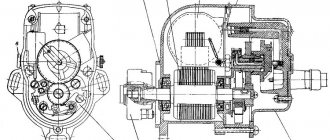
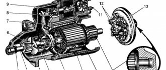
Types of starters
The differences between starters of various modifications lie in the design of the engagement devices; the electrical part is the same for all. The principle of operation and the design of two main components are different: a friction shock absorber and an automatic release mechanism.
Classic version
The operating principle of a classic type starter imposes restrictions on the characteristics of the clutch gear and the diameter of the flywheel. The gear pair cannot have a tooth ratio higher than 16/18, which requires the use of series excitation of the electric motor windings. The disadvantage of a classic starter is low efficiency, high heating, and a bulky excitation winding. Idle mode is dangerous for the device, since the electric motor can “go wild.” The advantage of a car starter with independent excitation is increased efficiency, reduced size, and no overheating. They obtain independent excitation in three ways, taking into account the operating principle of the electric motor:
- connecting the winding to a current source independent of the armature (controlled excitation);
- installation of permanent magnets on the stator (uncontrolled excitation);
- parallel connection of the winding (parallel excitation).
With planetary gearbox
Only the second option is suitable for the car, improved by a planetary gearbox built into the starter housing. The advantages of this type of design are as follows:
- The drop in battery voltage when starting the internal combustion engine does not affect the magnetic field of the electric motor;
- a multi-pole magnetic system is more compact than an electromagnetic system;
- the operating principle of the magnetic system allows you to increase efficiency;
- cheap ferrous powders, from which magnets are made, reduce the cost of the starter;
- planetary gearbox adapts the characteristics of the electric motor to the crankshaft speed;
- During a cold start, less current is consumed and starting reliability increases.
The operating principle of a planetary gearbox involves high gear wear. To increase the service life, the main gear is molded from thermosetting plastic under pressure and reinforced with bronze. Noise during operation is reduced, strength and wear resistance are increased. The use of hard graphite in commutator brushes and the removal of copper powder from the material increased the overhaul period of this unit. There are types of drive mechanisms: inertial, electromechanical, combined. Freewheels can be ratcheted, roller, or friction-ratchet.
I like1I don't like
Adjustment features
Magneto adjustment is carried out if the unit cannot perform the functions assigned to it, while all elements of the mechanism are intact. The magneto is adjusted by measuring the gap between the contacts of the interrupter assembly, while the engine crankshaft should be turned by the flywheel. The shaft rotates until the contact divergence is greatest. Let's adjust the gap by loosening the bolt that secures the contact post and turning the post of holes, which is installed in the eccentric slot.
When the gap is adjusted, it is necessary to test the mechanism - this will determine the correctness of the process. If everything is done correctly, then sparking failures can be avoided.
Loading …
Useful videos
Different branded walk-behind tractors produced by well-known brands differ from each other in the design of the built-in ignition system. To know how to correctly adjust this important element, we offer videos that contain the correct procedure for setting up the ignition system on the most common models of walk-behind tractors.
For walk-behind tractors of the Neva brand: For models of the Agro brand: For agricultural units produced by the Ural brand; For Mole walk-behind tractors: For Zubr models: For Salyut brand walk-behind tractors: For Honda agricultural implements: For the model range produced by the Cascade company: For MTZ brand walk-behind tractors:
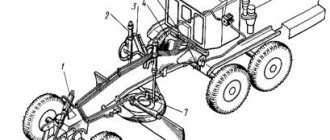
Installing magneto T-170 on the starting engine
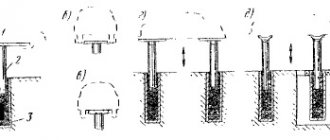
Disconnect the spark plug wire and remove the spark plug from the first cylinder (closest to the magneto). Determine the compression stroke in this cylinder; Rotate the engine crankshaft using the starting handle, covering the spark plug hole with your finger until compression is felt in the cylinder. Continuing to rotate the crankshaft, align mark B (Fig. 115) “Clamp” on the flywheel rim with mark A (mark) on the clutch housing hatch.
Rice. 115. Position of the starting motor flywheel when installing a magneto
A - mark (mark) on the hatch of the clutch housing; B — “Clamp” mark on the flywheel rim; C - “ВМТ1Ц” mark on the flywheel rim.
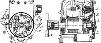
On the magneto, unscrew two screws 9 (
) and remove the screen together with the distributor cap 14. Set the driver 1 (Fig. 116) to the position corresponding to the moment of spark formation on the first electrode (the driver is turned to the left towards the number “1” stamped on the screen cover).
Rice. 116. Installation of the magneto at the moment the breaker contacts begin to open
I — view of the magneto screen cover; II - view of the magneto starting accelerator.
In this case, slot B on the starting accelerator body, in which the end of the spring is fixed, should be on the left side, when looking at the magneto mounting flange, and the axis of cams 2 of the starting accelerator should pass beyond the vertical axis of the magneto at an angle K equal to 5...10° in direction of rotation (in the direction of arrow C). In this position, install the magneto with a flange gasket on the bracket studs, inserting the cams of the starting accelerator into the grooves of the magneto drive shaft, and secure, without tightening, with nuts. Then, without changing the position of the flywheel (the “Clamp” mark is aligned with the mark on the hatch of the clutch housing) and turning the magneto body in one direction or another along the grooves in the flange, set the breaker contacts 25 and 26 () to the beginning of opening, and then finally secure magneto. The beginning of contact opening corresponds to the coincidence of the mark on the cam with the arrow of the distributor plate.
The moment the opening begins is precisely determined by an electrical device, in the circuit of which the movable 25 and fixed 26 contacts of the magneto breaker are connected in series. Replace the fixed contact with ground.
A break in the electrical circuit of the device will indicate the moment the contacts begin to open. The control light in the device circuit will go out.
If such a device is not available, determine the moment when the opening begins using a piece of tissue paper inserted between the contacts.
When the contacts open, the tissue paper is freely removed.
After setting the ignition timing and securing the magneto housing to the flange with nuts, install and secure the screen assembly with the distributor cap to the magneto.
Insert the wires into the distributor sockets.
The ends of the wires must be cut straight, and the wire cores must not protrude from the rubber insulation. Insert the ends of the wires into the output channel so that the needle enters the middle of the wire and the end of the wire touches the bottom all the way. Otherwise, a spark may break through to ground. Secure the inserted wires with clamp nuts.
Connect the wires coming from the distributor to the engine spark plugs: the wire from terminal “1” () of the distributor to the spark plug of the first cylinder (closest to the magneto), and the wire from terminal “2” to the spark plug of the second cylinder. The numbers are stamped on the magneto screen cover.
The gap between the spark plug electrodes is 0.6...0.7 mm by bending the side electrode.
Make sure that the massaging device for the additional output is in good working order: the contact (cap) of the output should be pressed by a spring to the magneto cover. It is not allowed to operate a magneto with an additional terminal that is not massed, as this will cause failure of the magneto.
Connect to the remote terminal 29 () of the magneto ignition switch the wire going to the VK-403 switch (see Fig. 211) of the locking mechanism, gearbox, and the wire going to the ignition switch button on the instrument panel.
Reliable magneto ignition in various homemade engines
In the seventies, while studying at a rural school, we began to study tractors. We started training with the simplest PD-12 starting engine, with which we easily understood the principle of operation of a two-stroke engine
We immediately paid attention to the magneto, with the help of which sparking occurred at the right moment on the spark plug. The idea arose to try to use a magneto on a moped engine
The fact is that at that time I had an old moped and three engines for it without ignition coils.
Finding a magneto was not a problem; almost all of my friends’ fathers worked as machine operators, and someone at home probably had an “ignition” for the starter lying around. Magneto can be left-handed or right-handed; for the moped, the left-hand one from the YuMZ-5 tractor was needed. It took a long time to figure out how to securely secure the magneto and connect it to the engine shaft. As a result, it was connected through a tubular spacer with welded eyes for bolting the magneto to the engine; rotation to the magneto was transmitted through a coated starter gear, which served to drive the magneto.
The design was cumbersome, but the engine worked properly. The second time I had to deal with installing a magneto was when a retired neighbor gave me an IZH-49, a motorcycle quite common in the 70s. It was not possible to find a “live” six-volt battery in the village, so my friends and I decided to equip the engine with a magneto. To do this, it was true that the right casing had to be cut off, leaving only the clutch drive mechanism in it, and the part that covered the generator had to be removed; the left magneto was secured in the same way, through a tubular spacer with a fouled starter gear.
The old IZH-49 began to work like a clock. Subsequently, without much hesitation, I installed a magneto on the Ant scooter. Well, it’s quite simple, you don’t need any spacers, it’s attached directly to the engine air intake, a rectangular hole is cut in the side trim covering the engine, and the appearance is not spoiled by the protruding magneto housing. At one time, homemade snowmobiles began to be made in villages. Of course, the engine for rotating the propeller was a launcher with a motorcycle cylinder from IZH - Planet.
To make the launcher as light as possible, it was assembled from the two front halves of the launcher body and therefore, it was necessary to make homemade tricks when trying to secure the magneto. The original connection between the engine shafts and the magneto was invented by my neighbor. He used a flange joint, made from small moped sprockets connected together by a double-row chain. It would seem that semi-homemade engines are a thing of the past; stores have a large selection of all kinds of engines and spare parts for them, but recently I had to return to the old reliable magneto again.
A friend of mine constantly invents something from old car parts; he recently bought a rotten Oka from a disassembly facility, but the main transmission components and engine were in good working order. From them he made a small truck with a passenger seat so that he could go to the forest to pick mushrooms, berries, and also go fishing. I couldn’t adjust the engine for a long time; there was a problem with the ignition. Seeing how he was suffering, I jokingly suggested that he install a two-contact magneto from a stationary Ulyanovets engine.
He seized on this idea and within an hour, the magneto was already in place of the distributor; surprisingly, even the fasteners fit. The Oka engine with a magneto started working steadily at low speeds and, when the air damper was opened, it sharply picked up speed. So, the old, reliable and simple ignition - magneto - will continue to be in demand among DIYers for a long time.
How to set the ignition on a walk-behind tractor?
Adjusting the ignition may be necessary if you have to repeatedly pull the starter cable or the engine does not start immediately, but after a delay.
You need to do the following:
- Place a square on the spark plug. The body is securely pressed against the cylinder head, the element rotates in the other direction from the hole on the cylinder head;
- The crankshaft turns. You need to tighten the starter cable a couple of times. When the cable is pulled, a blue spark should be visible that jumps between the electrodes;
- If there is no spark, check the gap from the flywheel magnetic shoe to the starter. The optimal distance is 0.1 millimeters.
So, installing the ignition will not take more than half an hour. If you perform simple manipulations correctly and in a timely manner, you can prevent wear of other parts and systems of the walk-behind tractor under high loads.
Health check
Before you start diagnosing the magnet, you need to make sure that the problem really lies in this unit. To do this, check the entire circuit and make sure that there are no other reasons for the trimmer failure.
- You must first carefully examine the reel for cracks and other external defects in the body. You will then need to check all the elements and components that conduct current and make sure they are clean.
- The next step is to check the high voltage wire. They must be in good condition and securely attached to the contacts, free of rust and undamaged insulation.
- The next step is to check the spark plug. As a result of careless actions, the user often disconnects it from the high-voltage wire, and then improvises and creates an improvised mount. It should be understood that any poor connection in this place will significantly reduce the power of the spark plug's electric arc.
- Then make sure that the candle is in good condition. By filling the mower with low-quality gasoline, the service life of this part is significantly reduced. In addition, it may be flooded or have a large amount of soot, which interferes with operation. Sometimes the spark plug even gets stuck and won’t come off.
- Next you need to inspect the switch. On trimmers and chainsaws made in China, it often breaks.
Having completed all these steps and eliminated the listed components from the list of possible causes of failure, you should begin checking the coil. This can be done in several ways.
Method 1
The first method of checking the ignition coil involves the use of special equipment (stands). He's not home. It can only be found in service centers.
Method 2
Diagnosing a magnetometer using a multimeter is a solution that can be done independently using such a measuring device. In this case, you need to do the following.
- Turn on the resistance mode on the measuring device and set the value to 200 ohms to test the primary winding.
- Connect the multimeter's electrodes to the magnet's "ground" and output pin. If the winding is not damaged, the resistance will fluctuate from 0.4 to 2 ohms.
- Turn on the 20-tester to diagnose the secondary winding. In this case, the first probe is connected to ground, and the second is installed in the spark plug cap. Normal values are at least 4-6 pcs. If the circuit is damaged, the tester will show infinity, and in case of a short circuit. Zero.
Exact information on how the tester should look when checking the primary and secondary windings can be found in the trimmer operating instructions.
Method 3
If you don't have a multimeter, you can test the coil another way.
The following steps are required for diagnosis:
- Open the lid that covers the cylinder;
- Remove the high-voltage wire cap from the spark plug without unscrewing the part itself to maintain compression;
- Insert the nail firmly into the capless cap, it will simulate the center electrode of the spark plug;
- Tie the cap to the cylinder with dielectric material so that the gap between the spark plug electrode and the weight varies from 5.5 to 7 mm (it is recommended to specify the exact distance for the specific model in the user manual), but the part does not come into contact with the weight;
- Run the engine several times to start the engine while holding the ignition button in the on position;
- If a spark appears, you should consider what color it is.
A normal white or bluish spark, but a weak orange or yellow flash indicates a broken coil.
Often, a cold magnet produces a powerful spark, but when heated, due to a defect in the internal components, it does not conduct current. Once the boiler coils have cooled, they will restart and cut the grass with a fishing line or knife before heating the magneto. This is not normal behavior and the coil must be replaced.
How to check the ignition coil on a walk-behind tractor?
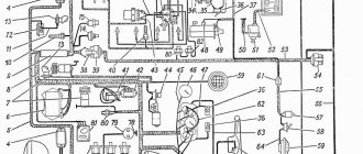
The ignition coil of a walk-behind tractor produces a spark that ignites the fuel. The presented diagram allows you to familiarize yourself with the principle of its formation. Ignition can be non-contact (first photo) or contact (second photo) depending on the principle of operation.
Initially, the coil is inspected. It may have cracks, dents and other mechanical damage. If the coil design is intact, you need to look for another cause of the malfunction.
The following problems may occur:
- Coil resistance data is measured. In this case, you need to have an idea of the key parameters under which this resistance occurs;
- a spark detection device is used. The cost of such a device is quite high;
- spark plug is used. It is turned inside out and applied to the cylinder. Next, pull the starter cable and watch for a spark.
The listed methods should be used if it is impossible to seek qualified help. During operation, it is important to ensure that you do not get an electric shock.
It is quite possible to carry out repairs yourself, following simple tips. To make the job easier, you can watch the video instructions.
For walk-behind tractors of brands such as Neva, Ural, Agro, Zubr, Salyut, Krot, Kaskad, MTZ and Honda, the setup steps are completely identical.
Diagnostics of the technical condition of the unit
As for diagnosis, it is carried out as follows:
- First you need to connect the high voltage cable to the voltage output.
- The other end of the cable should be approximately 0.5-0.7 cm from the device.
- In this position, the wire should sharply rotate the rotor in the direction of rotation. If the magnet is adjustable, the spark must pass through the rotation of the rotor between the wire contact and the housing. If it is missing or too weak, barely noticeable, most likely the device should be checked for faults and, if necessary, adjusted.