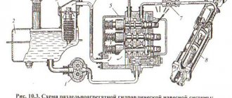
A hydraulic machine is a special equipment in which the fluid supplied from a pump transfers its mechanical energy to turbines (so-called hydraulic motors). There is another option - this is a machine that imparts mechanical energy to the liquid flowing through it (in other words, a pump).
A hydraulic machine that takes energy from flowing water consists of:
- electric generator;
- turbine;
- feeder or special channels.
The pump is one of the most common units. They are used in agriculture, construction, chemical, metalworking, textile and food industries.
Hydraulic machines are units that can move various types of liquids and gases, as well as generate energy from the flowing fluid (hydraulic motors). It is the creation and movement of fluid flow that is the main purpose of hydraulic machines.
Hydraulic press design: principle of operation, diagram
Modern mechanisms, machines and machine tools, despite the seemingly complex structure, are a collection of so-called simple machines - levers, screws, gates and the like. The operating principle of even very complex devices is based on the fundamental laws of nature, which are studied by the science of physics. Let us consider, as an example, the design and operating principle of a hydraulic press.
Hydraulic jack
What is a hydraulic press
A hydraulic press is a machine that creates a force that significantly exceeds that initially applied. The name “press” is rather arbitrary: such devices are often actually used for compression or pressing. For example, to obtain vegetable oil, oilseeds are strongly pressed, squeezing out the oil. In industry, hydraulic presses are used to manufacture products by stamping.
But the principle of a hydraulic press can be used in other areas. The simplest example: a hydraulic jack is a mechanism that allows, with a relatively small effort of human hands, to lift loads whose mass obviously exceeds human capabilities. The operation of a variety of mechanisms is based on the same principle - the use of hydraulic energy:
- hydraulic brake;
- hydraulic shock absorber;
- hydraulic drive;
- hydraulic pump.
The popularity of mechanisms of this kind in a variety of fields of technology is due to the fact that enormous energy can be transmitted using a fairly simple device consisting of thin and flexible hoses. Industrial multi-ton presses, booms of cranes and excavators - all these machines, indispensable in the modern world, work effectively thanks to hydraulics. In addition to industrial devices of gigantic power, there are many manual mechanisms, such as jacks, clamps and small presses.
How does a hydraulic press work?
To understand how this mechanism works, you need to remember what communicating vessels are. This term in physics refers to vessels connected to each other and filled with a homogeneous liquid. The law of communicating vessels states that a homogeneous fluid at rest in communicating vessels is at the same level.
If we disturb the state of rest of the liquid in one of the vessels, for example, by adding liquid, or by applying pressure on its surface in order to bring the system into an equilibrium state, which any system strives for, the level of liquid in the remaining vessels communicating with this vessel will increase. This happens on the basis of another physical law, named after the scientist who formulated it - Pascal's law. Pascal's law is as follows: pressure in a liquid or gas is distributed equally to all points.
What is the operating principle of any hydraulic mechanism based on? Why can a person easily lift a car that weighs more than a ton to change a tire?
Mathematically, Pascal's law looks like this:
The pressure P depends directly proportional to the applied force F. This is understandable - the harder you press, the greater the pressure. And inversely proportional to the area of the applied force.
Any hydraulic machine consists of communicating vessels with pistons. The schematic diagram and structure of a hydraulic press are shown in the photo.
Imagine that we pressed on a piston in a larger vessel. According to Pascal's law, pressure began to spread in the liquid of the vessel, and according to the law of communicating vessels, in order to compensate for this pressure, the piston in the small vessel rose. Moreover, if in a large vessel the piston has moved one distance, then in a small vessel this distance will be several times greater.
When conducting an experiment or a mathematical calculation, it is easy to notice a pattern: the distance by which pistons move in vessels of different diameters depends on the ratio of the smaller to the larger piston area. The same thing will happen if, on the contrary, force is applied to the smaller piston.
According to Pascal's law, if the pressure obtained by the action of a force applied to a unit area of the piston of a small cylinder is distributed equally in all directions, then the same pressure will be exerted on the large piston, only increased by as much as the area of the second piston is greater than the area of the smaller one.
This is the physics and design of a hydraulic press: the gain in strength depends on the ratio of the areas of the pistons. By the way, a hydraulic shock absorber uses the opposite ratio: a large force is absorbed by the shock absorber hydraulics.
The video shows the operation of a model of a hydraulic press, which clearly illustrates the operation of this mechanism.
The design and operation of a hydraulic press obeys the golden rule of mechanics: while winning in strength, we lose in distance.
From theory to practice
Blaise Pascal, having theoretically thought through the principle of operation of a hydraulic press, called it “a machine for increasing forces.” But more than a hundred years have passed from the moment of theoretical research to practical implementation. The reason for this delay was not the uselessness of the invention - the benefits of the machine for increasing strength are obvious. Designers have made numerous attempts to build this mechanism. The problem was the difficulty of creating a sealing gasket that would allow the piston to fit tightly to the walls of the vessel and at the same time, allow it to slide easily, minimizing friction costs - after all, rubber did not yet exist.
The problem was solved only in 1795, when the English inventor Joseph Bramah patented a mechanism called the “Brahm press.” Later this device began to be called a hydraulic press. The operation scheme of the device, theoretically outlined by Pascal and embodied in the Brahma press, has not changed at all over the past centuries.
metall.trubygid.ru
Types of hydraulic motors
There are three types of hydraulic motors and they all have internal moving parts that are driven by incoming flow, their name is:
— Gear motor
— Vane motor
— Piston engine
Displacement and torque
The amount of time a motor produces is called torque. This is the rotational force of the motor shaft. Torque is a measurement of force per unit length and does not include speed.
The torque of the motor is determined by the maximum pressure and volume of fluid it can move during each cycle. The speed of the motor is determined by the amount of flow. More flow, faster speed.
Torque is the force of rotation of the motor shaft
Torque equals force × distance
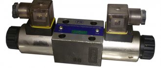
Valve classification
What types of valves are there?
Valves are controls in a hydraulic system. Valves regulate pressure, direction of flow, and amount of flow in a hydraulic system.
There are three types of valves:
— Pressure control valves
— Directional control valves
— Value control valves
In the figure below you can see how the valves work.
Pressure control valves
These valves are used to limit hydraulic system pressure, unload a pump, or adjust chain pressure. There are several types of pressure control valves, some of them are relief valves, pressure reducing valves and relief valves.
Directional control valve
This valve controls the flow direction of the hydraulic system. A typical direction control valve is a directional control valve and spool valve.
Value control valve
This valve controls the oil flow rate of the hydraulic system.
Control occurs by limiting the flow or diverting it. Several different types of magnitude control valve are the flow control valve and the flow division valve.
These valves are controlled in various ways: manually, hydraulically, electrically, pneumatically.
Pressure control valves
The pressure control valve is used for the following purposes:
System Pressure Limitations
Reducing pressure
Setting the Incoming Circuit Pressure
Unloading pump
A safety valve is sometimes called a safety valve because it reduces excessive pressure when it reaches an extreme level.
The safety valve prevents system parts from being overloaded.
There are two types of safety valve:
Direct acting safety valve that simply opens and closes.
Pilot line safety valve , which has a pilot line to control the main safety valve.
The direct acting safety valve is usually used in places where the flow volume is small and the operation is infrequently repeated. A pilot line relief valve is required in areas where a large volume of oil must be reduced.
Directional Control Valves
This valve controls the flow of oil, much like a traffic controller controls traffic. These valves:
— Check valve
— Spool valve
Various types of directional control designs are used.
A check valve uses a poppet and a spring to direct flow in one direction. A spool valve uses a movable cylindrical spool. The spool moves back and forth, opening and closing passages for flow.
Check valve
The check valve is simple. It is called a single flow valve. This means that it is open to flow in one direction, but closed to oil flow in the opposite direction.
In the figure below you can see the operation of the check valve. This is a check valve that is designed for through flow in one line. The poppet valve opens when the inlet pressure is greater than the outlet pressure. When the valve is open, oil flows freely. The poppet valve closes when inlet pressure drops. The valve interrupts the flow in the reverse direction and stops the flow under the action of the outlet pressure.
Spool valve
A spool valve is a typical control valve that is used to control the operation of an actuator. What is commonly called a control valve is a spool valve. The spool valve directs the flow of oil to start, carry out and finish work.
When the spool moves from the neutral position to the right or left, some channels open and other channels close. In this way, oil is supplied to and from the drive. The spool flange tightly blocks the incoming and outgoing oil flows. The spool is made of durable material and has a smooth, precise, strong surface. It's even plated with chrome to resist wear, rust and damage.
The spool valve in the picture shows three positions, neutral, left and right.
We call it four-position because it has four possible directions, which are directed into both chambers of the cylinder, into the tank and into the pump. When we move the spool to the left, the oil flow is directed from the pump into the left cylinder cavity and the flow from the right cylinder cavity is directed into the tank. As a result, the piston moves to the right.
If we move the spool to the right, the actions are exactly the opposite, and accordingly the piston moves to the right. In the central position, neutral, the oil is directed into the tank. The channels in the wallpaper of the cylinder cavity are closed.
Value control valves
As we wrote earlier, the magnitude control valve works in one of two directions. It either blocks the flow or changes its direction.
The flow control valve is used to control the speed of the drive by sensing the flow. Metering involves measuring or adjusting the flow rate to or from an actuator. A flow splitting valve regulates the volume of flow, but also splits flows between two or more circuits.
The flow split valve controls the amount of flow, but also splits the flows between two or more circuits.
Proportional flow divider
The purpose of this valve is to divide the flow from one source.
The flow divider in the figure below divides the flows in a ratio of 75-25 at the output. This is possible because input #1 is larger than input #2.
Lesson "Hydraulic machines"
Working with the presentation. Explanation of new material. Slide 2 - slide 8
Performing the experiment “Hydraulic machines”.
Now let’s look at the structure and principle of operation of a hydraulic machine.
A hydraulic (from the Greek hydraulics - water) machine consists of two cylinders of different diameters, inside which pistons can move. The space is filled with mineral oil.
Since two cylinders are communicating vessels, if there is no load on the pistons, the liquid is installed in the cylinders at the same level.
If a weight is placed on one of the pistons, the liquid will begin to move until equilibrium is established again.
On the slide we see that a hare sitting on one piston of a hydraulic machine balances two hares sitting on the other piston. Why? Let's answer this question. Let's draw a diagram of a hydraulic machine. (Students draw a diagram in their notebook).
F1 and F2 are the forces acting on the pistons, S1 and S2 are the areas of the pistons.
Based on Pascal's law, what can we say about the pressure p1 and p2?
These pressures are equal.
What is the pressure under the small piston?
p1=;
What is the pressure under the large piston?
p2=;
Therefore, = , from where, using mathematical transformations, we obtain that = .
Conclusion: the force F2 is as many times greater than the force F1, how many times the area of the larger piston is greater than the area of the small one. (Students write down everything on the slide in their notebook).
For example, if the area of the large piston is 500 cm2, and the small one is 5 cm2, and a force of 100 N acts on the small piston, then a force 100 times greater, i.e. 10,000 N, will act on the larger piston.
Thus, with the help of a hydraulic machine, a small force can balance a large force.
Therefore, one hare balances two birds with one stone.
Ratio = shows the gain in strength. For example, in the example given, the gain in strength is 100.
So, we can answer the question: “Why does a driver change a tire easily?”
Answer. The result is a gain in strength.
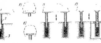
A hydraulic machine used for pressing (squeezing) is called a hydraulic press.
Video: “Hydraulic press.”
The pressed body is placed on a platform connected to a large piston. A small piston creates a lot of pressure on the liquid. This pressure is transmitted without change to every point of the liquid filling the cylinders. Therefore, the same pressure acts on the larger piston. But since its area is larger, the force acting on it will be greater than the force acting on the small piston. Under the influence of this force, the larger piston will rise. When this piston rises, the body rests against a stationary upper platform and is compressed. A pressure gauge, which measures the pressure of a liquid, is a safety valve that automatically opens when the pressure exceeds the permissible value.
From the small cylinder to the large one, liquid is pumped by repeated movements of the small piston.
Hydraulic presses are used where greater force is required. For example, for squeezing oil from seeds in oil mills, for pressing plywood, cardboard, hay. In metallurgical plants, hydraulic presses are used in the manufacture of steel machine shafts, railway wheels and many other products. Modern hydraulic presses can produce hundreds of millions of newtons of force.
Millions of cars are equipped with hydraulic brakes. Tens and hundreds of thousands of excavators, bulldozers, cranes, loaders, and lifts are equipped with a hydraulic drive.
Hydraulic jacks and hydraulic presses are used in huge quantities for a variety of purposes - from pressing tires onto carriage wheels to lifting drawbridge trusses to allow ships to pass on rivers.
Assignment for groups
Problem solving
No. 1. Two communicating vessels with different cross sections are filled with water. The cross-sectional area of a narrow vessel is 100 times smaller than that of a wide vessel; a weight of 1 kg was placed on a narrow piston. What weight must be placed on the wide piston to keep the system in equilibrium?
Task No. 2. Based on the figure, determine the gain in force that the hydraulic machine provides?
Task No. 3. Based on the picture, can you determine the weight of the ball?
Problem No. 4: The small piston of a hydraulic jack, under the influence of a force of 500 N, dropped by 15 cm. At the same time, the larger piston rose by 1 cm. What force will act on the larger piston?
xn--j1ahfl.xn--p1ai
Gear
Rotary hydraulic machines of this type have found application in lubrication systems, road and agricultural special equipment, and mobile hydraulic structures. Their advantages include:
- simplicity of design;
- operation at frequencies up to 5000 rpm;
- light weight;
- compactness.
Notable disadvantages:
- working pressure up to 20 MPa;
- low efficiency;
- small resource;
- pulsation problems.
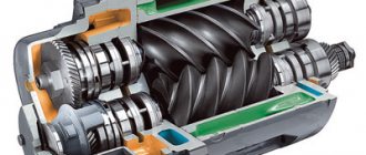
The working displacing elements of the structure are two gears. They differ in the type of engagement:
- External. From the inlet side, the gears rotate in different directions, capture the liquid in the cavities of the teeth and move it along the walls of the housing to the outlet of the pump. When the teeth engage, the working fluid is pushed out of the recesses towards the exit of the housing.
- Internal. The operating principle does not change. The fluid is transferred to the discharge area in the cavities between the gear teeth along the surface of the auxiliary crescent-shaped separator. Pressure pulsation and noise levels in such units are reduced.
Hydraulic press in physics
Definition of hydraulic press
Operating principle of a hydraulic press
The operating principle of a hydraulic press is based on Pascal's law. If you act on the small piston with a force, then pressure will arise under the small piston:
According to Pascal's law, this pressure will be transmitted without change in all directions to any point in the liquid, including points under the large piston. Therefore, the pressure under the large piston is:
Equating the right sides, we get:
From the last relationship it is clear that the force with which the liquid acts on the large piston is greater than the force on the small piston as many times as the area of the large piston exceeds the area of the small one. Thus, the hydraulic press gives a gain in strength.
Examples of problem solving
| Did you like the site? Tell your friends! | |||
www.solverbook.com
Specifications and selection options
The main technical characteristics of the hydraulic pump are:
- Rotation speed, rpm.
- Working volume displaced per shaft revolution, cm3/rev.
- Operating pressure.
Remember! The basic units for measuring pressure have the following ratio: 1 atm=1.013 bar=0.101 MPa=1.03 kgf/cm2.
The selection of a pump for a specific hydraulic system is made taking into account the following criteria:
- Type of element that displaces liquid - piston, gear, plate.
- Requires a manual or electric hydraulic pump.
- Working pressure limits.
- What viscosity medium can the mechanism work with?
- Working volume.
- Frequency interval of operation.
- Ease of maintenance.
- Dimensions.
- Price.
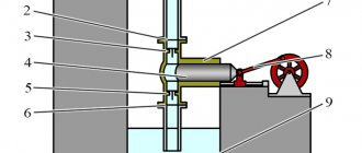
6.7. The simplest hydraulic machines
Liquids are practically incompressible and transmit pressure evenly throughout the entire volume. This property is widely used in various branches of technology (hydraulic drives, hydraulic automation, hydraulic brakes, amplifiers, etc.).
The principle of their operation is based on the following: let there be two interconnected cylinders of different diameters (Fig. 23).
| Rice. 23 | Let us apply some external force P1 to the piston of the smaller cylinder, thereby creating pressure on the surface of the liquid . |
This pressure is uniformly transmitted to all points of the space filled with liquid. Then the force will act on the piston of the larger cylinder
.
Thus, the more the cross-sectional areas of the cylinders differ from each other, the greater the force we will obtain in such hydraulic devices.
6.8. Archimedes' Law
Let us determine the force of fluid pressure on a submerged body A of volume W
| Rice. 24 | Let's imagine that a volume is allocated in a liquid, exactly the same as body A. This volume of liquid is in equilibrium under the action of two forces (Fig. 24): 1) the pressure force of the liquid P on the surface of the selected volume, 2) liquid gravity equal to rWg and directed vertically downwards. |
Consequently, the force P is equal to the force of gravity of the selected volume of liquid, directed in the opposite direction, that is, vertically upward, and applied in the center of the volume, i.e. at the same point at which the gravity force of the allocated volume of liquid is applied.
Point D is called the center of displacement.
Archimedes' law. The force of fluid pressure on a body immersed in it is applied at the center of displacement, directed vertically upward and equal to the force of gravity of the fluid displaced by the body
.
The force P is called the Archimedean force, W is the volumetric displacement, and rW is the displacement.
6.9. Equilibrium and stability of bodies completely immersed in a liquid
If the gravity force G of body A is greater than the Archimedean force P, then the resultant of these forces (P and G) is directed downward and forces the body to sink to the bottom. Thus, if P
If the gravity force G of a body is less than the Archimedean force P, then the resultant of these forces (P and G) is directed vertically upward and forces the body to rise to the surface. When a part of the body leaves the liquid, the pressure force on the remaining immersed part of the body decreases accordingly, due to which the magnitude of the upward-directed resultant, causing the body to float, also decreases; as a result, with some partial immersion of the body, equilibrium is established and the body finds itself floating on the surface of the liquid. Thus, at P>G the body floats to the surface of the liquid.
In order for a body not to sink to the bottom or float up, it is necessary that P=G.
The stability of a floating body is its ability to return to its original equilibrium position after the cessation of the force that caused the roll.
Three cases are possible (Fig. 25).
a B C
Rice. 25
1) the center of gravity C lies below the center of displacement D,
2) the center of gravity C is above the center of displacement D,
3) the center of gravity C coincides with the center of displacement D.
In the first case, the equilibrium is stable, since during a roll a pair of forces arises that tend to return the body to its original position.
In the second case the equilibrium is unstable, in the third it is indifferent.
studfiles.net
Hydraulics and operation
Three elements of work
When there is any work, then certain conditions are necessary to perform this work. You need to know how much force is needed. You need to decide how quickly the work needs to be done and you need to determine the direction of the work. These three operating conditions: force, speed and direction are used in hydraulic terms as shown below.
Hydraulic machines. Basic definitions and classification.
Hydraulic machines
Classification of hydraulic machines
Hydraulic machines are devices for converting mechanical energy into flow energy and vice versa - for converting the energy of a moving fluid into mechanical energy. According to their functional purpose, hydraulic machines are divided into two main groups:
- pumps;
- hydraulic motors.
***
Pumps
Pumps are one of the most common types of machines used in almost all branches of mechanical engineering, construction, industry and agriculture. They are used in hydromechanical structures of many mechanisms and units, in pipelines for various purposes (oil pipelines, gas pipelines, transport pipelines, etc.), in water supply, heating, cooling, ventilation systems, in boiler installations, household appliances, etc.
Pumps (like hydraulic motors) are used in hydraulic transmissions, where the main element is a hydraulic drive, the purpose of which is to transfer fluid energy from the pump to the executive working element (hydraulic motor, hydraulic cylinder, etc.). Pumps used to transport liquids and gases (sometimes solid objects placed in a liquid or gaseous medium) through pipelines have a slightly different purpose - here the pumps serve to impart the energy of motion to the transported substance.
The pump converts the mechanical energy of the drive motor (electric, thermal engine, manual drive, etc.) into the energy of the flow of working fluid, i.e. the pump is the power source for the hydraulic drive or hydraulic system.
According to GOST 17398-72 “Pumps. Terms and definitions”, according to the principle of operation and the type of energy supplied to the liquid, pumps are divided into two main groups:
- dynamic pumps;
- positive displacement pumps.
Dynamic pumps convert the mechanical energy of the drive motor predominantly into the kinetic energy of the working fluid flow by increasing its speed. Dynamic pumps include pumps that move fluid through a force that increases its kinetic energy (blades and impeller blades, external force field, external flow with greater kinetic energy, etc.). A characteristic feature of dynamic pumps is that the liquid moving in them has a constant connection with the inlet and outlet pipes, which structurally distinguishes them from pumps of the second group - volumetric ones.
Dynamic pumps include vane pumps, electromagnetic ones (using a magnetic field to accelerate the flow of fluid), as well as pumps using friction and inertia forces (jet, vortex, labyrinth, screw, worm, etc.).
A special group of widespread dynamic pumps consists of vane pumps, which transmit energy to the fluid through a rotating working element - a vane wheel. Energy transfer in such pumps occurs through the dynamic interaction of the wheel blades with the fluid flowing around them.
Vane pumps include centrifugal, axial and diagonal pumps. Centrifugal pumps are vane pumps with liquid movement through the impeller from the center to the periphery, axial pumps are vane pumps with liquid movement through the impeller along its axis. An example of an axial vane pump is a water-jet propeller of a ship, the propeller of which is the impeller.
***
Positive displacement pumps are designed to convert the mechanical energy of the drive electric motor mainly into the potential energy of the flow of working fluid by increasing its pressure. Volumetric pumps include pumps whose operating principle is based on increasing the external pressure on a closed volume of liquid from the surfaces limiting the closed volume, and periodically displacing liquid from the closed volume into the outlet pipe (pressure line).
The increase in pressure is carried out by reducing the closed volume along the path of liquid transfer from the input (supply) line to the pressure line. In this case, the closed volume alternately communicates either with the input (supply line) or with the outlet (pressure line) of the pump.
Examples of the most common positive displacement pump designs are piston, plunger, diaphragm, rotary and gear. Positive displacement pumps also include some special devices used to lift and move liquids:
- hydraulic rams, the operation of which is based on the principle of using the pressure resulting from hydraulic shock;
- airlifts are devices for lifting liquids in wells by injecting air into the wells and creating a difference in volumetric masses in the column of air-saturated liquid being lifted and the liquid surrounding this air-saturated column.
The use of pumps for human household needs has been known since ancient times. The first designs of these machines used a muscular (manual or animal) drive and were intended for water intake from wells, reservoirs, etc. Currently, hundreds of different pump designs have been developed that can satisfy a wide variety of needs in mechanical engineering, medicine, technology, construction and other areas of human activity.
Based on the pressure created, low-pressure (up to 20 m), medium-pressure (20..60 m) and high-pressure (over 60 m) pumps are distinguished. In addition, pumps are classified by power and flow (micropumps, small, small, medium, large), by speed (low-speed, normal, high-speed), by design and some other parameters.
***
Hydraulic motors
A hydraulic motor converts the energy of the flow of working fluid received from the pump into the mechanical energy of the output link (for example, a cylinder rod or hydraulic motor shaft), which directly or through a mechanical transmission drives the working part of the machine. Thus, the engine is a consumer of fluid energy in the hydraulic drive.
Hydraulic motors, as a rule, have “design twins” among pumps, i.e. most known hydraulic pump designs can be used as a hydraulic motor. This means that almost any pump can perform two functions - transfer energy to a fluid from mechanical devices, or take it away from a moving fluid, transferring it to mechanical devices. For this reason, hydraulic motors, like hydraulic pumps, can be classified into two main groups - dynamic (impellers, turbines, etc.) and positive displacement (similar to positive displacement pumps). Standing somewhat apart are volumetric hydraulic motors - hydraulic cylinders, which, however, can also be used as pumps.
***
The main operating parameters characterizing hydraulic machines and their operating modes are pressure (or pressure), flow (for a pump) or flow (for a hydraulic motor), power (required and useful), and efficiency.
***
Positive displacement pumps
kat.ru
Types of hydraulic pumps
Today, many machines have one of three pumps:
- Gear pump
— Vane pump
— Piston pump
All pumps operate on a rotary piston type; the liquid is driven by the rotation of a part inside the pump.
Piston pumps are divided into two types:
— Axial piston type
— Radial piston type
Axial piston type pumps are so called because the pump pistons are positioned parallel to the pump axis.
Radial piston pumps are so called because the pistons are positioned perpendicular (radially) to the axis of the pump. Both types of pumps perform reciprocating motion. The pistons move back and forth and use rotary piston motion.
Displacement of hydraulic pump
Displacement means the volume of oil that the pump can pump or move in each cylinder.
Hydraulic pumps are divided into two types:
— Fixed working volume
— Variable working volume
Fixed displacement pumps pump the same amount of oil each cycle. To change the volume of such a pump, it is necessary to change the pump speed. Variable displacement pumps can change oil volume depending on the cycle. This can be done without changing the speed. Such pumps have an internal mechanism that regulates the output amount of oil. When the pressure in the system drops, the volume increases; when the pressure in the system increases, the volume decreases automatically.
| Fixed displacement pump | Variable displacement pump |
| Power | |
| Design |
Drive classification
What is a drive?
The drive is the part of the hydraulic system that produces power. The drive converts hydraulic energy into mechanical energy to do work. There are linear and rotary drives. The hydraulic cylinder is a linear drive. The force of the hydraulic cylinder is directed in a straight line. The hydraulic motor is a rotary drive. The output force is torque and rotary action.
Hydraulic cylinders
Hydraulic cylinders are like a lever. There are two types of cylinders.
Single acting cylinders.
Hydraulic fluid can only move to one end of the cylinder. The return of the piston to its original position is achieved by gravity.
Double acting cylinders.
Hydraulic fluid can move to both ends of the cylinder, so the piston can move in both directions.
In both types of cylinders, the piston moves in the cylinder in the direction in which the liquid pushes against the piston. Various types of seals are used in pistons to prevent leakage.