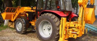
Technical description of front loader TO-30
The main market requirement for equipment demand is performance, reliability, ease of use and price. All these indicators together affect demand, since this equipment must recoup all costs and make a profit. It is difficult to imagine the effective work of municipal, road, construction, mining and other organizations without the use of front loaders . Front-end bucket loaders have different modifications and a load capacity of 2.7 tons; 3.3t.; 3.5 t.; 4t. Modifications for various modifications affected the hydraulic system of the working equipment and steering hydraulic cylinders. The leveling mechanisms equipped with front loaders . Each new model improves the automatic operation of the bucket from the digging position to the upper unloading position and back to improve efficiency (efficiency), kinematics of the operation of loading equipment, which significantly affects the final result of the work performed and its productivity. Naturally, organizations are interested primarily in communicative technology for maintaining, cleaning, landscaping and maintaining territories in proper form and readiness for assigned tasks. This includes cleaning up construction, household and natural waste, snow removal, and storing goods and materials. And therefore, each organization, taking into account its type of activity, selects, in particular a loader for efficient production in its industry. of front loaders produced leads the end buyer to the question of a detailed study of the design of the technical unit, its certificates of conformity and operating characteristics. And subsequently, as a consumer, the ability to replenish failed spare parts, components, and spare parts for the loader. Suppliers of spare parts and components to the plant for the assembly line are evaluated. The difference in the power elements of the working equipment and frame structures and their impact on the usefulness of the loads and, as a consequence, the efficiency on productivity is determined. The process of development and improvement is constantly ongoing. So the first models loader were repeatedly modernized, in the process of development, design changes were made, trials (experiment). This includes the installation of engines from different factories: Altai and Minsk of various modifications, differing in power. The mechanical and hydromechanical gearbox U35615 can be called unchanged. This is a structurally proven hydromechanical gearbox GMKPP U-35.605 / 615 produced by Murom and Polish GMKP. It is relevant and appropriate to use an articulated frame in the design in order to increase maneuverability. Equipping the loaders with a comfortable cabin with the greatest possible visibility, equipped with a fan and heating. The use of unsteered axles with a self-locking differential makes it possible to make maximum use of the vehicle's weight to create better traction and grip characteristics. Constant expansion of attachments: mounting hooks for piece loads, load forks and forks with grips, buckets of various capacities.
The loader has a large thermo-vibration and noise-insulating cabin, an adjustable operator's seat, sprung with shock absorbers. The loader is equipped with a hydraulic steering wheel, has two semi-frames connected by an articulation and is equipped with dual-circuit foot shoe brakes on all wheels. The presence of a pedal block ensures simultaneous braking and disabling the transmission of the loader . Based on experience in the production and improvement of loaders , weak and strong points were identified. In the process of refinement and equipment, new models were produced with the same names, and loaders were discontinued. The question arises of servicing forklifts manufactured 20–30 years ago. The LLC TD SPETSZAPCHAST campaign has been working in this field for a long time, repairing forklifts
, supply of spare parts for
loaders
.
Delivers POMs, cardan shafts, hydraulic cylinders, units, drive axles, etc. All this was achieved thanks to partnerships with former suppliers to the forklift . This relationship helps to provide the necessary spare parts for the forklift to the end user in a short time and at low prices. The campaign of TD SPETSZAPCHAST LLC does not divide suppliers and its clients into ranks, some more, some less. We are all the same in this big mechanism, and if one goes wrong, the whole mechanism goes wrong. This is our motto. We are not engaged in lip service, but want to work and earn money by providing you with a small service. Contact the LLC “TD “SPETZAPCHAST”” company for qualified assistance and your equipment, loaders , will be in good condition.
This TO-30 loader model was discontinued in 1997.
Single-bucket loaders should be used for loading and unloading operations with various types of cargo (bulk, lump, piece, etc.), for moving cargo over short distances, for excavation work for developing soil and backfilling pits and trenches, and for auxiliary work.
With the help of loaders, you can scoop, move and load bulk and lump materials (sand, crushed stone, gravel, stone, light aggregates), soil and other materials into vehicles or into a dump.
Loaders with power over 100 HP. With. can be used for layer-by-layer development of soil in a dense body of groups I-III, as well as group IV with preliminary loosening.
For use in loading operations, loaders are equipped with replaceable working parts (buckets of various types and capacities, forks, jaw grips, blockless crane booms, equipment with an increased unloading height), as well as rippers mounted on the rear side of the base tractor (tractor).
Pneumatic wheel loaders have higher mobility and maneuverability than tracked loaders and can work in cramped conditions (small construction sites, cargo yards, warehouses, etc.), as well as at facilities (freight processing points) with dispersed volumes of work.
In accordance with GOST 12568-67 “Single-bucket construction loaders. Types, main parameters and dimensions”, the industry provides for the production of the following standard sizes: on pneumatic wheels (PK) five standard sizes with a load capacity of 2, 3, 4, 6 and 10 tons, on crawler tracks (PG) four standard sizes with a load capacity of 2.3, 4 and 6 tons .
Single-bucket front loaders with pneumatic wheels. The industry produces pneumatic wheel loaders with a lifting capacity of 1.8 tons TO-6 (D-561B), 3 tons (TO-18) and 4 tons TO-11 (D-660) (see Table 23).
Designs of pneumatic wheel loaders with a lifting capacity of 6, 10, 15 and 25 tons are being developed.
The TO-6 (D-561B) loader (Fig. 4) is mounted on the basis of a self-propelled pneumatic wheel chassis with a rigid frame. The attachment consists of a frame, a boom hinged on the portal, a hinged lever system and a hydraulic drive (two double-acting hydraulic cylinders for raising and lowering the boom and two for rotating the working element).
The main working element is a tilting loading bucket of normal capacity.
The SMD-14 diesel engine is used to drive the loaders.
The transmission of the base chassis is hydrodynamic; it includes a hydromechanical gearbox, cardan transmissions, power take-off gearboxes, front and rear axles (Fig. 5).
The hydromechanical transmission during the process of scooping material or cutting soil makes it possible to automatically adjust the operating speeds of the loader. The loader is equipped with hydraulic steering and pneumatic brakes.
The undercarriage of the loader is a rigid welded frame with two drive axles, rigidly suspended from the frame, without elastic elements.
The hydraulic system includes hydraulic pumps NSh-46, hydraulic distributor GRU-25, a tank for working fluid, filters, valves, pipelines and high-pressure hoses (Fig. 6). The loader has a single closed all-metal cabin.
The TO-17 loader (Fig. 7) is mounted on a special unified pneumatic wheel chassis with an articulated frame. The presence of an articulated frame on the loader provides it with advantages compared to TO-6 loaders (D-561A and D-561B) with a rigid frame, including: – the same design of the front and rear driving non-steer axles; – increased maneuverability and reduced turning radius.
Maneuvering the machine is carried out by shifting the semi-frames at an angle to one another and rolling the driving fixed wheels at different angular speeds. Thanks to the presence of an articulated frame (the angle of rotation of the semi-frames is 35°), the work cycle of the loader is 33-40 s, and the controllability of the loader is also improved, especially at maximum transport speed.
Rice. 4. Pneumatic wheel loader TO-6 (D-561B) with a rigid frame 1 - tipping bucket; 2 - boom; 3 — turning levers; 4 — hydraulic cylinders for turning the bucket; 5 — hydraulic cylinders for lifting the boom; 6 - portal; 7 — turning rods
Rice. 5. Kinematic diagram of the transmission of the TO-6 pneumatic wheel loader 1 - engine; 2 – transfer gearbox; 3 – torque converter; 4— hydromechanical gearbox; 5 – front driving axle; axle reducers; 7 _ transfer case; 9 - rear
Rice. 6. Diagram of the hydraulic drive of the TO-6 (D-561B) loader 1 - hydraulic pumps; 2 - hydraulic distributor; 3 — hydraulic cylinders for turning the bucket; 4 — hydraulic cylinders for raising and lowering the boom; 5—hydraulic cylinders for opening and closing the double-jaw bucket; 6 - safety valves; 7 - tank for working fluid
Rice. 7. Pneumatic wheel loader TO-17 with articulated frame 1—tipping bucket; 2 — rocker arm of the bucket rotation levers; o arrow; 4 — portal of the front half-frame; 5 — hinges connecting the front and rear semi-frames; 6 — rear semi-frame with cabin and engine
The power plant of the loader is a six-cylinder diesel engine AM-41 with a power of 90 hp. With.
Rice. 8. Diagram of the hydraulic drive of the working equipment of the TO-17 loader 1 - gear hydraulic pump; b - hydraulic cylinders for turning the bucket; 3 — hydraulic cylinders for lifting the boom; 4 - hydraulic distributor; 5 — hydraulic distributor bucket rotation section; 6 - hydraulic switch; 7 — built-in filter; 8 - tank for working fluid
The loader has a single-seat cabin, which is equipped with an adjustable seat with a hydraulic shock absorber, equipped with a fan, a dust separator and two windshield wipers.
The TO-18 loader (Fig. 9) is mounted on a special pneumatic wheel chassis with an articulated frame. The angle of rotation of the semi-frames (relative) is ±35°. The front axle suspension is rigid, the rear axle suspension is balanced.
The power plant of the loader is a six-cylinder diesel engine A-01MD.
Rice. 9. TO-18 pneumatic wheel loader with articulated frame
Rice. 10. Kinematic diagram of the TO-18 loader transmission 1 - hub gearboxes: 2 - rear drive axle; 3 - engine; 4 — transfer gearbox; o - torque converter; 6 — gearbox; 7 — front drive axle; 8 - transfer case
Power take-off gearbox is mechanical, four-shaft with shutdown; torque converter - single-stage; dual-range gearbox with gear shifting and reverse using friction clutches (Fig. 10).
Power is transmitted to unified drive axles with hub planetary gearboxes through cardan drives.
The steering mechanism is hydraulic, driven by an NSh-46P hydraulic pump and an emergency axial plunger hydraulic pump.
The brakes on all wheels are pneumatically controlled shoe brakes and automatically disable the transmission when you press the left pedal. The hand brake on the transmission is a shoe brake with a mechanical drive.
The working equipment is lever-jointed with a hydraulic drive of the working body, the hydraulic control unit is a three-section spool valve P26-160 (Fig. 11).
The main working part of the loader is the tilting loading bucket.
The following can be used as replaceable working bodies: buckets of various types and capacities, forks, jaw grips, and a blockless crane boom.
Rice. 11. Diagram of the hydraulic drive of the working equipment of the TO-18 loader / - tank for working fluid; 2 — main filter; 3 – hydraulic switch; 4 – drain from the steering system; 5 — oil line to the steering pump; b - hydraulic distributor; 7 — axial piston pump; 8 — hydraulic cylinders for turning the bucket; 9 — pressure gauge; “/ — boom lift hydraulic cylinders; 11 — oil line to the cylinders of replaceable equipment
The all-metal double cabin is equipped with a heating and ventilation system, an adjustable seat with shock absorbers, and windshield wipers.
The TO-11 (D-660) loader (Fig. 12) is mounted on the base of an industrial modification of a pneumatic wheeled tractor with an articulated frame K-702. The hydromechanical transmission of the base tractor provides automatic change in traction force depending on the load on the working element.
Rice. 12. Pneumatic wheel loader TO-11 (D-660) with an articulated frame 1 - tipping loading bucket; 2 — levers of the hinge-lever system; 3 - boom; 4 — hydraulic cylinders for turning (tilting and tipping the bucket); 5 - portal; 6 — basic tractor K-702
The articulated frame of the base tractor ensures high maneuverability and constant traction of the wheels with the ground.
Attached loading equipment consists of a portal, a boom, a rocker arm of an articulated-lever system, hydraulic cylinders and a working element.
The portal - a welded sheet structure with axles for pivoting the boom and the hydraulic cylinder for turning the bucket - is rigidly bolted to the cargo half-frame.
The boom is a welded sheet structure consisting of two box-section spars. The boom is raised and lowered by two double-acting hydraulic cylinders.
The hinge-lever mechanism consists of levers and rods made of thick sheet steel.
Rice. 13. Diagram of the hydraulic drive of the working equipment of the TO-11 (D-660) loader 1 - throttle; 2 — hydraulic cylinders for raising (lowering) the boom; 3 — hydraulic cylinders for turning the bucket; 4 — hydraulic cylinders for closing the jaws of a two-jaw bucket; 5 - hydraulic distributor; 6 — hydraulic pumps; 7—tank for working fluid; in - filter
The hydraulic drive system of the working equipment (Fig. 13) includes two double-acting boom lift hydraulic cylinders, two double-acting hydraulic cylinders for turning the working body, an NSh-98 hydraulic pump with an independent drive, a valve-spool hydraulic control valve, a tank for working fluid, and a pipeline system (oil lines and flexible high pressure hoses).
The control of loading equipment is concentrated in a two-seater cabin equipped with a heating system, ventilation and windshield wipers.
Rice. 14. Semi-rotary loader TO-3 (D-451A), equipped with a double-jaw grab 1 - pneumatic wheel chassis; 2 and 7 - hydraulic cylinders; 3—lever system; 4— arrow; 5 - jib; b - grab; 8 - rotating device
Rice. 15. Kinematic diagram of the transmission of the TO-3 (D-451A) loader 1 - gearbox; 2 — cardan transmissions; 3 — transfer case; 4 and 5 — driving axles; 6 - engine; 7 - clutch-8 - reverse
Rice. 16. Diagram of the hydraulic drive of the TO-3 (D-451A) loader 1 and 5 - hydraulic cylinder for turning the platform; 2 — hydraulic cylinders for closing and opening the grab jaws; 3 — hydraulic cylinder for turning the jib; 4 — hydraulic cylinders for raising and lowering the boom; 6 — hydraulic distributor; 7— oil lines; 8 - filter; 9 - hydraulic pump; 10 - tank for working fluid
Semi-rotary pneumatic wheel loaders. Semi-rotary pneumatic wheel loaders are universal loading machines and are designed to perform small volumes of work, including in cramped conditions. The TO-3A (D-451A) loader (Fig. 14) is mounted on a pneumatic chassis with drive wheels and a 55 hp engine. With. The transmission of the loader is mechanical. The engine is connected to the transmission by a friction-type clutch.
The gearbox (Fig. 15) is a four-speed one from a GAZ-51 car. The transfer case has a rear axle disconnect mechanism. The front axle is used from a ZIL-164 car, and the rear axle from a ZIL-151 car, pneumatic brakes on all wheels.
The drive of the working parts of the loader is hydraulic (Fig. 16).
Due to the low traction and coupling qualities, it is recommended to use the loader with a double-jaw grab with a capacity of 0.4 m8, which does not require significant pressure forces when scooping materials.
Construction organizations are supplied with semi-rotary loaders of the KHON-053 and UN-050 models, which are manufactured by enterprises in Czechoslovakia.
Tracked front loaders. Loaders are mounted on modernized general purpose tractors or special industrial tractors.
Compared to non-wheeled loaders, tracked loaders, as a rule, have better traction and traction properties and lower specific ground pressure. This increases their maneuverability and increases the specific pressure forces on the cutting edge of the bucket.
The TO-2 (D-443A) loader (Fig. 17) with a lifting capacity of 1.5 tons is mounted on a DT-55A crawler tractor. The loader's attachments include a frame (gantry), a boom articulated on it, an articulated-lever system, a hydraulic system and a working element. The main working element is a tipping bucket. The set of additional replaceable working tools includes a universal double-jaw bucket, a blockless crane boom and a ripper mounted on the rear side of the tractor.
Rice. 17. Crawler loader TO-2 (D-443A) 1 - bucket; 2 — rocker arm of the hinge-lever system; 3 - boom; 4 — hydraulic cylinder for turning the bucket; 5 - portal; 6 - ladle; 7 - ripper
The hydraulic system of the loader (Fig. 18) consists of oil containers (tanks), hydraulic cylinders for raising (lowering) the boom and rotating the working element, oil lines and high-pressure hoses, an NSh-60V gear pump and a hydraulic divider.
The TO-7 (D-574) loader is mounted on the base of the DT-75BSG 3 t class crawler tractor (Fig. 19). The loader's attachments consist of a portal, a boom, an articulated-lever system, a hydraulic drive and working parts.
A valve is installed in the loader hydraulic system to limit the pressure level in the hydraulic cylinders when the distributor spool is closed; the standard bucket is equipped with a cutting edge made of 65G steel; The cabin of the base tractor is double-seater and equipped with heating and ventilation systems. All this improves the performance of the loader.
The TO-10 (D-653) loader (Fig. 20) with a lifting capacity of 4 tons is mounted on the basis of a caterpillar tractor of industrial modification T-130PG of class 6 tons with a power of 140 hp. With.
Rice. 18. Diagram of the hydraulic drive of the TO-2 (D-443A) loader 1 - main and additional tanks for working fluid; 2 - hydraulic pump; 3 - filter; 4 - hydraulic distributor; 5 — hydraulic cylinder for ripper drive; 6 — stop plugs; 7 — hydraulic cylinders for closing the jaws of a two-jaw bucket; 8—chokes; 9 — hydraulic cylinders for turning the bucket; 10 - safety valves; 11 — boom lift hydraulic cylinders
Loading equipment consists of a portal, boom, articulated-lever system, hydraulic drive and replaceable working parts.
The hydraulic drive (Fig. 21) includes two gear hydraulic pumps, a hydraulic distributor, two hydraulic cylinders for raising and lowering the boom, a tank for working fluid, safety valves, hydraulic locks, quick-release locking devices and a piping system.
The design of the TO-10A (D-653) loader on the T-130 general-purpose tractor has also been developed. The loader has been tested and prepared for mass production.
Rice. 19. Crawler loader TO-7 (D-574) 1 - tipping bucket; 2 - boom; 3— rocker arm of the hinge-lever system; 4 — engine guard; 5 — hydraulic cylinder for turning the bucket; 6 - portal; 7 — cabin of the base tractor; 8 — high pressure hoses; 9 — boom lift hydraulic cylinder
The TO-5 (D-543) loader (Fig. 22) with a lifting capacity of 5 tons is mounted on the basis of a special modification of the D-804PG tractor with a power of 180 hp. That is, it has a portal, a support frame, a boom, an articulated lever system, replaceable working bodies and hydraulic cylinders for driving the working body. The transmission of the base tractor is mechanical (Fig. 23).
The main working body is a two-jaw universal bucket.
The hinge-lever system ensures a constant angle of inclination of the working element during the process of raising and lowering the boom. To dampen hydraulic shocks and sudden changes in pressure, the hydraulic drive has a spring hydraulic shock absorber. The replaceable working bodies are controlled using a hydraulic drive from the driver’s cabin (Fig. 24).
The replaceable working equipment includes a main tipping bucket, a larger-capacity bucket, a jaw gripper, and a blockless crane boom.
Rice. 20. Tracked loader TO-SHA (D-653)
Rice. 21. Diagram of the hydraulic drive of the TO-YU (D-653) loader 1 - tank for working fluid; 2— gear pumps; 3—hydraulic distributor; 4 — hoseless rotary connection; 5 - quick release couplings; 6 — hydraulic cylinders for closing the double-jaw bucket; 7 - safety valve; 8 — hydraulic cylinder for turning the bucket; 9 - safety and check valves; 10 — boom lift hydraulic cylinders; 11 - filter
The design of the TO-5 (D-543S) loader has been experimentally developed, which is intended for use in areas with low negative temperatures.
The basic D-804PG tractor has a massive frame, wide track and rigid suspension.
A portal is welded to the tractor frame, on which a boom with working equipment is pivotally attached.
Rice. 23. Kinematic diagram of the transmission of the base tractor loader TO-5 (D-543) 1 - engine; 2 — clutch; 3 — gearbox; 4 — main gear; 5 — planetary rotation mechanism; 6 — driving sprockets; 7 — final drives
Rice. 24. Diagram of the hydraulic drive of the working equipment of the TO-5 (D-543) loader
The loader's replaceable working equipment includes: normal and large-capacity buckets, a double-jaw bucket, a timber grab and a mounting hook.
The main working part of the loader is a tipping bucket with a capacity of 2.8 m3.
To dampen the swing moments of a loaded bucket when transporting it over uneven terrain or when lifting, the loader is equipped with a spring-hydraulic jack.
Backward dump track loaders
Rear-dump tracked loaders differ significantly in layout and design from front-end loaders.
Loaders of this type are produced by industry in one model, TO-1 (T-157M). The loader is mounted on a hydraulically powered T-100MGP-1 crawler tractor (Fig. 25).
Rice. 22. Tracked loader TO-5
Rice. 25. Loader with backward unloading TO-1 (T-157M) 1 - protective device; 2 — basic crawler tractor; 3 - boom; 4 — lever mechanism; 5 - ladle; 6 — hydraulic cylinder for lifting the boom; 7 - buffer
The diagram of the loader hydraulic system is shown in Fig. 26, and the technical characteristics of the TO-1 (T-157M) loader are below.
Technical characteristics of the TO-30 front loader
| Name | Explanation |
| Loader type | TO-30 |
| Rated load capacity, i.e. | 2,2 |
| Nominal capacity of the main bucket, m3 | 1,8 |
| Breakout force, kN | 80 |
| Maximum bucket unloading height at unloading angle 45, mm | 2800 |
| Reach of the bucket edge at maximum unloading height, mm | 700 |
| Angle of rotation of semi-frames, degrees. | 40 |
| Turning radius | 5,05 |
| Total hydraulic cycle time, s | 29,9 |
| Let's rise | 6,5 |
| Unloading | 2.0 |
| Lowering | 5.0 |
| Total cycle time | 13,5 |
| Engine | Diesel D-243 |
| Power at 2200 rpm | 57.4 (78) kW (hp) |
| Working volume, l | 4,75 |
| Specific fuel consumption (per ton of loaded material), kg/t | 00,4 |
| Power, hp/min | 80 / 2 200 |
| Maximum torque, Nm | 280 |
| Fuel consumption, l/100 km | 17,0 |
| Productivity, t/h | 120 — 200 |
| dimensions | |
| Width (by bucket), mm | 2 400 |
| Length (bucket on supporting surface with teeth), mm | 6 400 |
| Height (in the cabin), mm | 3 290 |
| Track, mm | 1 840 |
| Base, mm | 2 450 |
| Wheelbase, mm | 2800 |
| Wheel track, mm | 1840 |
| Ground clearance, mm | 400 |
| Minimum turning radius, m | 5,2 |
| Maximum speed, km/h | |
| Forward | 35 |
| Back | 20 |
| Working | 0-6,1 |
| Transport | 0-35 |
| Tire size, inch | 14.00-20 NS 16 (370*508) |
| Transmission | Hydromechanical GMCP U-35.605 |
| Number of steps | 9 / 2 |
| Weight, kg | 7 250 |
| Manufacturer | Produced by JSC "Eagle-loader" |
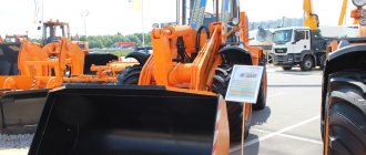
Special equipment / Loader / TO6
| On this page you can buy a diesel forklift Forklift TO6, manufactured in 2008, for RUB 700,000 Added: March 27, 2016, RUB 700,000 | |
| Model: | TO6 |
| Year of issue: | 2008 |
| Price: | RUB 700,000 |
| Description: | Mileage, km: 10000 Body type: Forklift Condition: excellent Power, hp: 6 Fuel: hybrid Body color: Yellow Year of production: 2008 Additional information: CDM833125 hp, capacity 3 tons, bucket volume 1.8 m3 Main characteristics Bucket volume, m31 ,8Operating weight, kg10 300 Load capacity, kg3 000 Wheelbase, mm2 850 Track width, mm1 850 Maximum turning angle, deg. 35 Boom lifting time, s? 6.0 Total hydraulic cycle time, s? 10.5 Minimum turning radius (At the level of the outer side of the bucket), mm 5 500 Minimum turning radius (at the level of the outer side of the bucket), mm4 865Dumping height, mm2 900Dumping depth, mm1 069EngineModelTD226B-6GPower, kW/rpm92/2200Maximum torque, rpm1400-1600TypeVertical, liquid cooling, 4-stroke, direct fuel injection, tour bonablowing .Nominal fuel consumption, g/kW*h210 Engine volume, l6.234 Operating pressure of the air compressor, MPa0.78 Filling tanks Hydraulic oil tank, l140 Fuel tank, l140 Travel speedI forward, km/h0~6.5II forward, km/h0~12III forward, km /h0~32I back, km/h0~6.8II back, km/h0~12.5III back, km/h0~33.5Torque converterType3-element, single-stage, single-phaseTorque conversion coefficient3.6Cooling typeLiquid coolingInlet oil pressure, MPa0 .50~0.65Output oil pressure (MPa)0.25~0.30GearboxTypeFixed shafts, constant mesh gears, non-synchronized.GearsThree - forward, three - reverse, manual shift (hydraulic)Axles and wheelsFinal driveSpiral bevel gear, single-stage reductionGear ratio5. 833:1 Tires 17.5-25 12PR Wheel speed reducer Type Cylindrical planetary gear Reduction ratio 3.882:1 Brake system Working brakes Disc, dry type with hydropneumatic drive, acting on 4 wheels Parking and emergency brake Disc, dry type Working pressure, MPa 0.65 ~ 0.78 R steering control TypeHydraulic steering Pressure in system, MPa14 Structure Series connection of two pumps Hydraulic pump Pump flow, l/min 80 System operating pressure 15.7 Air conditioning system (optional), heating Cooling, w4 500 Heating, w5 800 |
| Location: | Russia / Perm region / Perm |
Photos
Contact Information
| Contact Information: | City: PermContact person: Anton Nikolaevich |
| Company: | Anton Nikolaevich |
| Source: | auto.59.ru |
| Share: |
See also on sale
www.stroyteh.ru