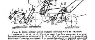
harvesting part DON-1500
consisting of a threshing drum 8 and a lattice concave (deck) 7; breaker beater 11; keyboard straw walker (coarse heap separator) 13; cleaning (small heap separator), consisting of upper 22 and lower 23 louvered sieves, an extension of the upper sieve 20 and a fan 28; finishing device 27, consisting of a hammer drum and a solid deck; transporting devices in the form of screws 21, 24, 26 and elevators.
On the frame of the thresher there is a grain bin 12 with an unloading device, a cabin 9 with a control platform, an engine 10 and a chassis, including a front axle of driving wheels and a rear axle of steering wheels 19.
The stacker 15 is a chamber formed by two sidewalls, an upper sheathing, a hinged bottom 17 with a finger grille and a rear valve. The working bodies of the stacker are the rake mechanisms of the straw filler 14 and the chaff filler 18.
The technological process of the combine is as follows.
The strip of stems of the harvested crop, separated by dividers from the unmowed part of the stem stand, is tilted by the reel rake towards the cutting device. The cut stems are fed by a reel to an auger, which moves them from the edges to the center of the header. The auger finger mechanism transfers the cut mass to the spacer intermediate beater and the feeder chain-slat conveyor, which directs the mass flow into the threshing apparatus.
Due to the blows of the drum whips and the friction that occurs when pulling the stems between the rotating drum and the stationary concave, grain is separated from the ears (threshing). The main part of the threshed grain (70...95%) and small straw heap spills through the concave grate onto the transport board.
The straw (coarse) heap thrown out of the threshing apparatus is directed by a breaker to the straw walker. On the straw walker keys that move in a circular motion, the straw is shaken, the remaining threshed grain and small heap are separated from the straw and along the solid bottom of the inclined keys are directed to the transport board. The straw coming off the keys is fed into the stacker chamber by the rake of the straw filler.
The grain heap, released through the concave and on the straw walker, moving along the transport board, is divided into fractions: the grain goes down, accumulating in the recesses, and the straw heap rises up. From the transport board, the grain heap enters the upper cleaning sieve, and the grain hits the surface of the sieve first.
Combine Don-1500B, Don-1200B. Instructions - part 32
5) bring the combine to the header so that the grips (hooks) 1 (Fig. 170) of the feeder chamber fall under the pipe 2 of the spacer, lift the header, then using hooks 4 rigidly connect the feeder chamber with the spacer;
6) connect the hydraulic system of the header and feeder chamber with the hydraulic system of the combine;
7) place the reel on stands (Fig. 173);
fold back the covers 3 (Fig. 172) on the reel sliders 2, remove the safety chain 5 from the right support, then move the combine to the reel so that the sliders fall under the reel bearings 1, slightly lift the supports 4 using hydraulic cylinders, and then secure the bearings with the covers using bolts;
9) install the rollers on the leads of the eccentric mechanisms and connect them to the copiers;
10) install the screw jacks in the transport position;
11) lower the header onto the shoes and connect the rods of the reel movement hydraulic cylinders with the pins on the reel sliders;
12) in order to eliminate reel distortions, pump the hydraulic system by moving the reel several times in height and offset;
Note. If the misalignment in height or offset does not disappear during pumping, then unscrew the fitting of the hydraulic drive of the hydraulic cylinder, which lags behind in movement, by about half a turn, drain some of the oil along with the air that has entered the hydraulic system, then tighten the fitting;
13) install a rod with a bearing and a drive chain on the reel shaft, adjust the chain tension;
14) install and adjust all other drive chains and belts, then install guards;
15) adjust the header balancing mechanism, for which:
release the balancing mechanism by installing pins 5 (Fig. 5) into the rack of the header body;
raise the header so that the shoes do not touch the ground (cross
stretch marks should sag freely);
screw the tension screws into the extension springs 3 so that a gap A of approximately 8 mm is formed between the screw heads and the supporting surfaces of the spherical bearings;
move the reel to the header body and lower it to its extreme position;
By rotating the bolts 7 and 7 of the spring blocks, adjust the mechanisms so that the load on the soil is approximately 30...40 kgf. In this case, the header, without freezing, should lower until the levers 72 stop in the brackets 18 (if the levers do not rest against the brackets, then the tension of the spring blocks should be loosened);
16) use a feeler gauge and visually check the condition of the seals in the area of the side shields and the lower transition shield in the transition zone between the header and the spacer (in the area of the side shields, gaps can be no more than 1.5 mm, in the area of the transition shield, gaps are not allowed);
17) check the oil and add it
TECHNOLOGICAL ADJUSTMENTS OF THE DON COMBINE
TECHNOLOGICAL ADJUSTMENTS OF THE DON COMBINE – Megatraining
| Home | About us | Feedback |
- Automation
- Automotive industry
- Anthropology
- Archeology
- Architecture
- Astronomy
- Entrepreneurship
- Biology
- Biotechnology
- Botany
- Accounting
- Genetics
- Geography
- Geology
- State
- Demography
- Woodworking
- Journalism and Media
- Zoology
- Invention
- Foreign languages
- Computer science
- Information Systems
- Art
- Story
- Cinema
- Shipbuilding
- Cooking
- Culture
- Lexicology
- Literature
- Logics
- Marketing
- Mathematics
- Mathematical analysis
- Materials Science
- Mechanical engineering
- Medicine
- Management
- Metallurgy
- Metrology
- Mechanics
- life safety fundamentals
- Occupational Safety and Health
- Pedagogy
- Political science
- Legal relationship
- Programming
- Production
- Industry
- Psychology
- Radio
- Miscellaneous
- Sociology
- Sport
- Statistics
- Construction
- Theology
- Technologies
- Tourism
- Manor
- Physics
- Physiology
- Philosophy
- Finance
- Chemistry
- Drawing
- Ecology
- Economy
- Electrical engineering
⇐ Previous4
| Average value of adjustment parameters | Rotation frequency Molotilny drum, min -1 | Rotation frequency fan, min-1 | Gap in MSU at output, mm | Gap between top blinds (lower) sieve, mm | |
| culture | mass moisture content, % | ||||
| Wheat | 9…12 | 650…760 | 650…750 | 6…7 | 12/7 |
| 13…16 | 760…830 | 750…850 | 5…6 | 15/8 | |
| 17…20 | 830;..900 | 850…950 | 4…5 | 18/9 | |
| Barley | 9…12 | 600…630 | 550…600 | 6…7 | 12/8 |
| 13…16 | 630…660 | 600…650 | 5…6 | 14/9 | |
| 17…20 | 660…700 | 650…700 | 3…4 | 16/10 | |
| Rye | 9…12 | 700…750 | 600…630 | 4…6 | 13/8 |
| 13…16 | 750…800 | 630…700 | 3…4 | 14/10 | |
| 17…20 | 800…850 | 700…750 | 2…3 | 18/10 | |
| Oats | 9…12 | 500…580 | 500…550 | 6…8 | 13/8 |
| 13…16 | 580…620 | 550…600 | 5…6 | 14/10 | |
| 17…19 | 620…650 | 600…650 | 4…6 | 16/12 | |
| Peas | 9…12 | 350…400 | 700…800 | 16…20 | 12/8 |
| 13…16 | 400…450 | 800…850 | 14…16 | 14/10 | |
| 17…19 | 450…500 | 850…950 | 12…14 | 16/10 | |
The selected adjustments and operating modes of the reel are specified.
The removal of the reel relative to the knife when harvesting tall, thick grains and with normal grain yield is carried out so that the lower part of the rake path is removed from the cutting apparatus in height by approximately 1/2 of the cut part of the stem. When harvesting tall and thick grains, the reel extension should be minimal, and when harvesting normal grains, the reel extension should be between the minimum and middle positions.
When harvesting low-growing grains (less than 40 cm), the lower part of the rake path is removed from the cutting device in height by 1/3 of the cut part of the stem, the horizontal extension of the reel is minimal (bars are installed on the rake).
When harvesting laid grains, the ends of the rake should lightly touch the soil, the reel horizontal extension should be maximum.
To prevent grain losses from knocking out, the reel rotation speed should minimally exceed the speed of movement of the combine. The main technological adjustments of the header and pick-up are given in tables 3 and 4.
TECHNOLOGICAL ADJUSTMENT OF THE HEADER FOR GRAIN HARVESTING
| Condition of the grain array | ||||||||||
Normal erect
Tall (over 80 cm)Combine speed, km/h12345678910123456789 Reel rotation speed, min—115182631364043464949151826313640434649| Cutting height, mm. Reel lifting. Reel extension, mm Gap, mm: between the auger and the bottom with the fingers and the bottom of the cutter and the bottom with the beater fingers and the attachment | 150¸180 0¸50 10¸15 12¸30 Minimum, at 23¸35 | Over 180 1/2 lengths of cut stems. The rods are completely in the cylinders 10¸15 20¸30 provided that the auger turns do not touch the header body 28¸35 |
| Condition of the grain array | Short (30…40 cm) | Lying down | ||||||||||||||||
| Harvester speed, km/h | 1 | 2 | 3 | 4 | 5 | 6 | 7 | 8 | 9 | 1 | 2 | 3 | 4 | 5 | 6 | 7 | 8 | 9 |
| Reel rotation speed, min-1 | 15 | 18 | 26 | 31 | 36 | 40 | 48 | 46 | 49 | 18 | 26 | 31 | 36 | 40 | 43 | 46 | 49 | 49 |
| Cutting height, mm Reel lifting Reel removal Gap, mm: between the auger and the bottom with fingers and the auger cutter and the bottom with beater fingers and spacer | 50¸100 50 From 1/3 of the length of the cut stems to the level The ends of the rake should touch the cut of the soil The rods are completely in the hydraulic rods The rods are extended to the maximum 10¸15 10¸15 12¸20 12¸20 Minimum, provided there is no interference with the auger turns body 28¸35 28¸35 |
TECHNOLOGICAL ADJUSTMENTS OF THE PICKUP PLATFORM FOR GRAIN HARVESTING
| Culture | ||||||||||
Wheat, rye, barley, oats
Wheat, barley, peasCharacteristics of the windrow Normal, laid on stubble with a height of 100 to 200 mm Failed, sprouted, laid on stubble with a height of up to 50 mm Combine speed, km/h12345678910123456————Pickup rotation speed, min-1148148159212265318371424475475 148148159212265318| Pick-up height (location of spacer bushings) Gap, mm: between the auger and the bottom with fingers and the bottom of the auger and cut-off with the beater fingers and spacer | Two bushings at the bottom All bushings at the top 10¸15 10¸15 12¸20 12¸20 Minimum, provided that the auger does not touch the platform body 28¸35 28¸35 |
To improve the quality of harvesting, the Don-1500 combine is driven in such a way that the general direction of lodging of the grain is at an angle of 45°, and the unmown field remains to the right; the combine should move less in the direction of lodging of grain, tailwinds, across the slope and plow furrows.
The technological adjustments of the threshing machine are adjusted in the order established in Table 37 (the digital designation refers to the order in which the combine is adjusted). After each adjustment, check the results separately. Each adjustment should not introduce more than 5% deviations in the operation of the thresher
After setting the combine for maximum productivity with minimum allowable grain losses, continue harvesting at the selected speed and use the handles to adjust the indicator for changes in the intensity of grain loss so that the lights located in its middle part are lit on the light display. Then, while driving at the same speed of the combine, by alternately changing the gaps in the concave and the drum rotation speed, the optimal values of these adjustments are selected, focusing on the indicator. With each adjustment, they drive at least 100 m or unload at least two kopecks. Similarly, the cleaning adjustments are specified using the indicator.
The quality of the combine's operation is assessed using standard methods.
⇐ Previous4
Recommended pages:
content .. 51 52 ..6.13
Operation of the stacker of the RSM-10B "Don-1500B" combine
All operations of filling the chamber and monitoring the normal process of hay formation are fully mechanized and partially automated using hydraulic control.
Control of a filled stacker is reduced to turning on the stack release mechanism with the button for opening the rear valve.
It is prohibited to dump a hay when turning.
During operation of the combine, it is necessary to monitor the operation and adjust the straw filler, chaff filler, bottom, rods, signaling device and hydraulic valve closing system.
In straw and chaff fillers, the tightening of the nuts and the adjustment of the crankshaft bearings are checked. Adjustment is made using shims. In correctly adjusted bearings with tightened bolts and no radial play, the shafts should turn by hand (with the chains removed). The positions of the straw discharge flap, the chaff beater comb and the tension of the chains are checked.
In the bottom, the tension of the springs and the position of the leading edge of the bottom relative to the floor filler tray are adjusted. The springs should be installed with the locknuts facing up, and the screw hooks should be screwed in the same amount, equal to approximately half the length of the thread. The tension of the springs is adjusted by rotating them by hand (with the locknut released). The position of the leading edge of the bottom is adjusted by changing the length of the bottom rods.
The front edge of the bottom should be parallel to the tray and be 10-40 mm below the edge of the tray.
By alternately adjusting the rods (with the valve closed), parallelism is achieved between the bottom and the tray.
The tension of the rear valve latching rods and the stacker opening rod must be such that the latches engage the valve hooks to the full tooth height and, when the stack unloading button is turned on, simultaneously disengage with the hooks. The warning device is adjusted so that when the rear flap is pulled all the way into the latch, the warning light does not light up.
The first row of piles is laid automatically by lower sensor 6 (Figure 5.28). Then the operator empties the stacker, focusing on the first row of stackers, while the lower position sensor serves as an indicator that the stacker is full. The upper sensor 5 is intended for alarm overflow of the accumulator.
Depending on the state of the harvested grain mass, the position of the sensors is adjusted in height. For this purpose, the rack 3 has five holes located at different heights.
When harvesting grain mass of normal moisture, bracket 4 with position sensors is installed in the upper position. With increased moisture content of the grain mass, the bracket moves along the holes of the rack to a lower position.
content .. 51 52 ..